Interface and Pin Description
Wiring Precautions
- GPIO logic level is 3.3V. If the output signal of a peripheral exceeds the allowable range, the pin may be damaged.
- A0 and A1 are not 5V tolerant. Pay special attention to the maximum input voltage when connecting analog signals.
- It is recommended to verify onboard resources before connecting external modules. Test onboard resources such as the RGB LED and LED matrix first, then connect sensors or actuators.
Do not directly drive loads such as motors, relays, or high-power LED strips with GPIOs. Such loads should be driven using driver modules, with separate power supply and common ground as required by the module.
Onboard User Interface
The onboard user interface requires no additional wiring and can be used for functional verification, status indication, and project debugging.
For specific usage instructions for Arduino App Lab, refer to Working with App Lab
1. LED Matrix
The LED Matrix is one of the main features of the Arduino UNO Q. The onboard 8×13 blue LED dot matrix is managed by the UNO Q STM32 microcontroller.
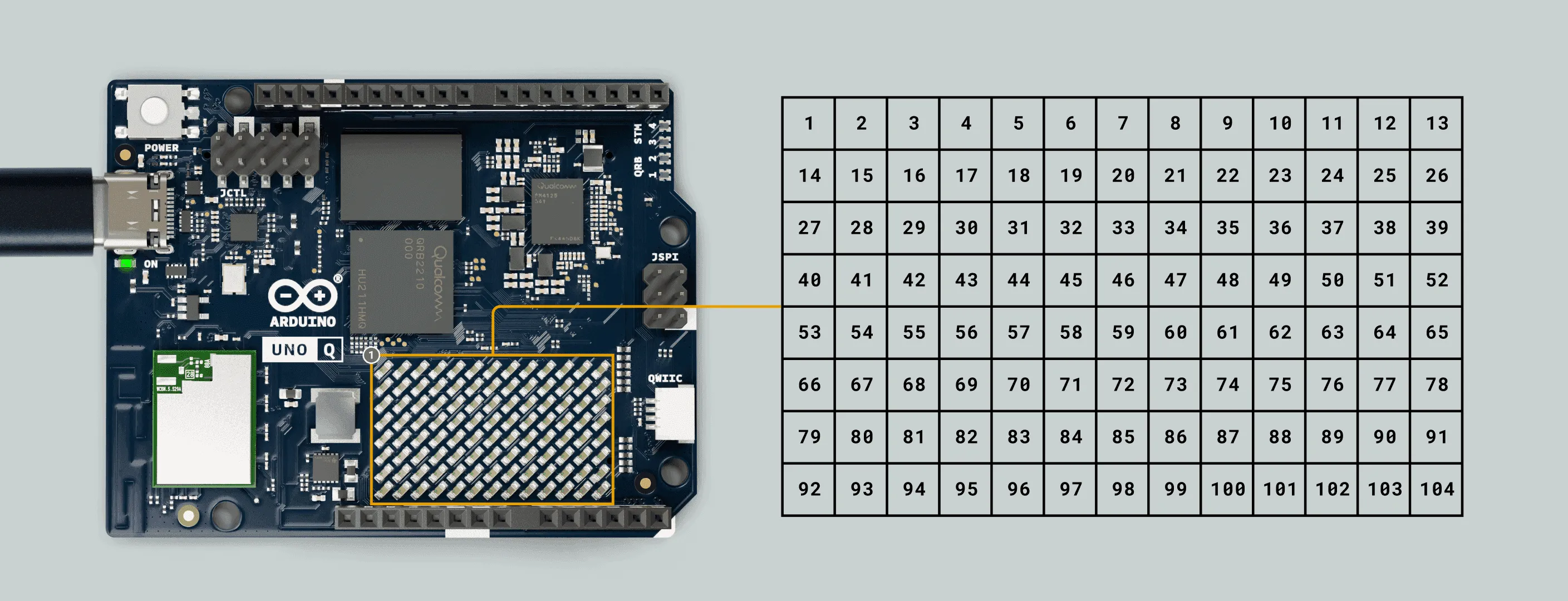
This LED dot matrix is flexible and can be used to display data, status indicators, icons, and even simple animations or small games. Below are some basic examples of the LED Matrix.
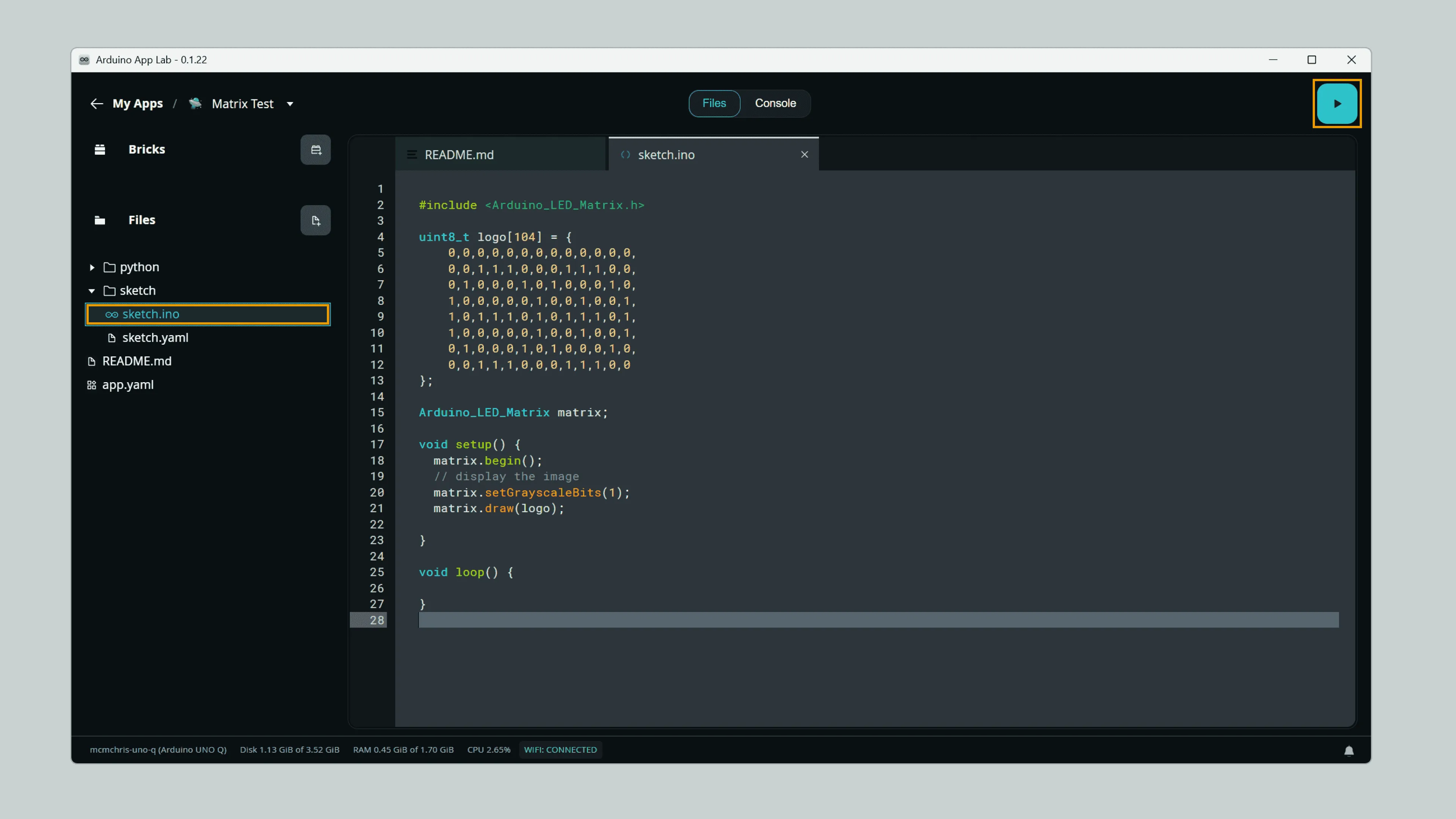
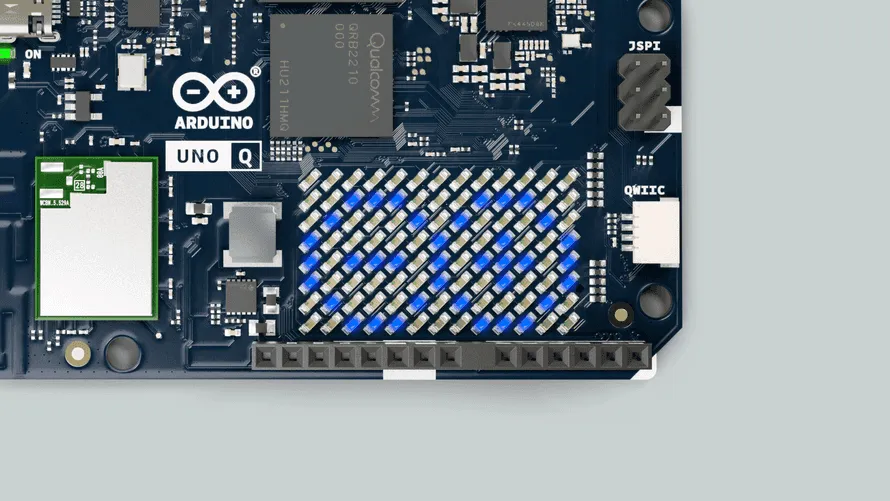
① Drawing an Image
This example demonstrates how to draw a custom pattern on the LED Matrix, using the Arduino Logo as an example.
You can copy the example code below into the Sketch area of a new App in Arduino App Lab.
Click to expand example code
#include <Arduino_LED_Matrix.h>
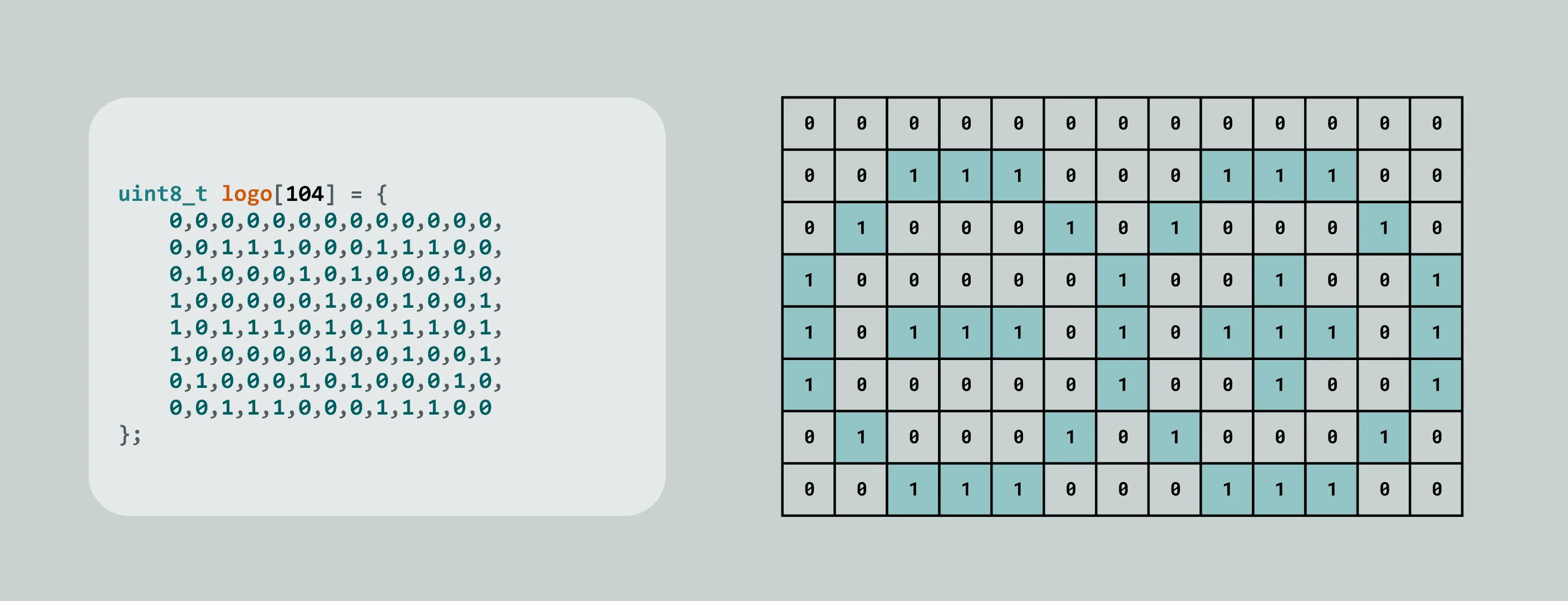
uint8_t logo[104] = {
0,0,0,0,0,0,0,0,0,0,0,0,0,
0,0,1,1,1,0,0,0,1,1,1,0,0,
0,1,0,0,0,1,0,1,0,0,0,1,0,
1,0,0,0,0,0,1,0,0,1,0,0,1,
1,0,1,1,1,0,1,0,1,1,1,0,1,
1,0,0,0,0,0,1,0,0,1,0,0,1,
0,1,0,0,0,1,0,1,0,0,0,1,0,
0,0,1,1,1,0,0,0,1,1,1,0,0
};
Arduino_LED_Matrix matrix;
void setup() {
matrix.begin();
// Display the image
matrix.setGrayscaleBits(1);
matrix.draw(logo);
}
void loop() {
}
② Brightness Adjustment
The LED Matrix supports 8 levels of grayscale (3-bit), so the brightness of each LED can be controlled individually.
You can set the number of grayscale bits using the setGrayscaleBits(bits) function, for example:
matrix.setGrayscaleBits(3); // 3-bit, corresponds to 8 brightness levels, range 0–7
Common grayscale conversion tools typically use 256-level grayscale (8-bit). The LED Matrix also supports this range and automatically maps it.
matrix.setGrayscaleBits(8); // 8-bit, corresponds to 256 brightness levels, range 0–255
This example demonstrates the grayscale brightness effect supported by the LED Matrix.
You can copy the example code below into the Sketch area of a new App in Arduino App Lab.
Click to expand example code
#include <Arduino_LED_Matrix.h>

uint8_t shades[104] = {
    0,0,0,0,0,0,0,0,0,0,0,0,0,
    1,1,1,1,1,1,1,1,1,1,1,1,1,
    2,2,2,2,2,2,2,2,2,2,2,2,2,
    3,3,3,3,3,3,3,3,3,3,3,3,3,
    4,4,4,4,4,4,4,4,4,4,4,4,4,
    5,5,5,5,5,5,5,5,5,5,5,5,5,
    6,6,6,6,6,6,6,6,6,6,6,6,6,
    7,7,7,7,7,7,7,7,7,7,7,7,7
};

Arduino_LED_Matrix matrix;

void setup() {
  matrix.begin();
  // display the image
  matrix.setGrayscaleBits(3);
  matrix.draw(shades);

}

void loop() {

}
Click the Run button in Arduino App Lab to run the App, and you will see the LED Matrix display a pattern with different brightness levels.
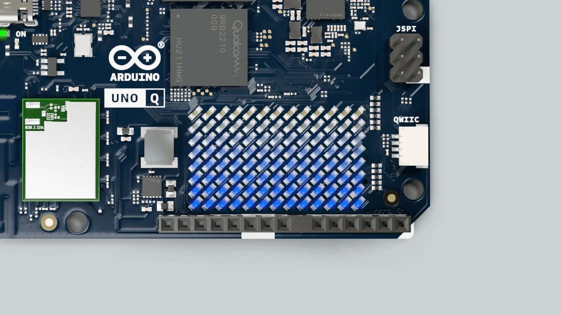
2. RGB LED
The UNO Q features 4 onboard RGB LEDs. 2 of them are controlled by the Qualcomm microprocessor (MPU), while the other 2 are controlled by the STM32 microcontroller (MCU).
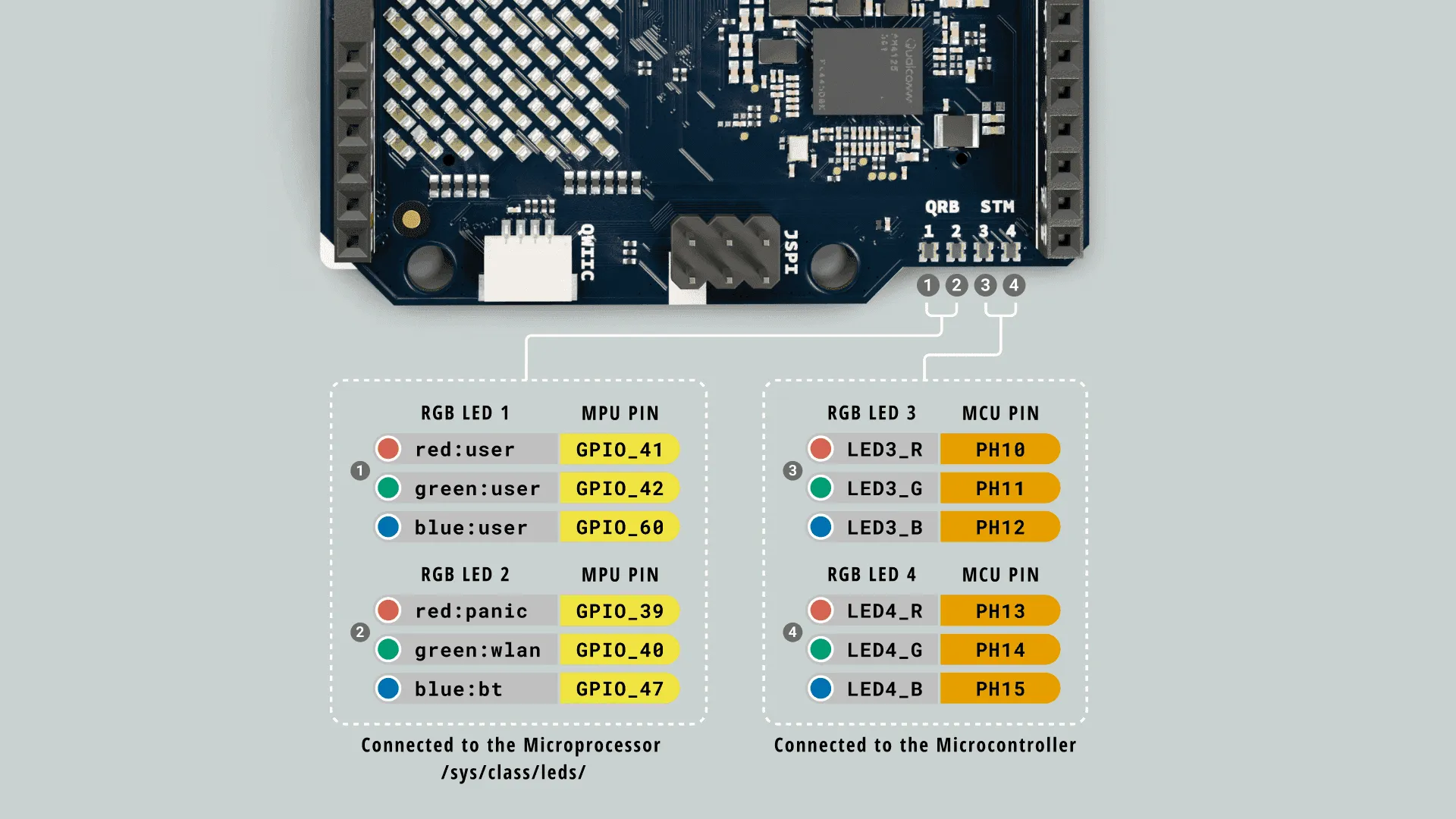
① RGB LEDs Controlled by MPU
LED_1 and LED_2 are controlled by the MPU.
In the UNO Q Linux system, dedicated LED control interfaces are provided. You can control these LEDs via the command line, SSH, ADB connection from a PC terminal, or by using the built-in terminal application in SBC mode, using /sys/class/leds:
echo 1 | tee /sys/class/leds/red:user/brightness   # Set HIGH / ON
echo 0 | tee /sys/class/leds/red:user/brightness   # Set LOW / OFF
RGB LED channel definitions are as follows:
LED_1:
- Red:
red:user - Green:
green:user - Blue:
blue:user
LED_2:
- Red:
red:panic - Green:
green:user - Blue:
blue:bt
LED 2 is used by default to display system status, such as PANIC, WLAN, BT, etc., but users can also control it manually.
In addition to the command line, you can also control these LEDs via Python scripts.
Click to expand Python script control method
First, create a new App in Arduino App Lab and copy the following script into the Python area of the App.
import time

from arduino.app_utils import App

LED1_R = "/sys/class/leds/red:user/brightness"
LED1_G = "/sys/class/leds/green:user/brightness"
LED1_B = "/sys/class/leds/blue:user/brightness"

LED2_R = "/sys/class/leds/red:panic/brightness"
LED2_G = "/sys/class/leds/green:wlan/brightness"
LED2_B = "/sys/class/leds/blue:bt/brightness"

def set_led_brightness(led_file, value):
    try:
        with open(led_file, "w") as f:
            f.write(f"{value}\n")
    except Exception as e:
        print(f"Error writing to {led_file}: {e}")

# turn off all LEDs
set_led_brightness(LED1_R, 0)
set_led_brightness(LED1_G, 0)
set_led_brightness(LED1_B, 0)
set_led_brightness(LED2_R, 0)
set_led_brightness(LED2_G, 0)
set_led_brightness(LED2_B, 0)

def loop():
    #blink the LED 1 RED segment
    set_led_brightness(LED1_R, 1)
    time.sleep(1)
    set_led_brightness(LED1_R, 0)
    time.sleep(1)

App.run(user_loop=loop)
You can also use the dedicated Linux module to control these LEDs. The Leds are as follows:
# Parameters correspond to R, G, and B colors respectively.
Leds.set_led1_color(1,0,0) # LED 1 in red
Leds.set_led2_color(1,0,0) # LED 2 in red
Remember to create a new App in Arduino App Lab and copy the following script into the Python part of the App:
import time
from arduino.app_utils import App
from arduino.app_utils import Leds

def loop():
    # Blink LED 1 in red
    # Turn on the LED red segment(1, 0, 0)
    Leds.set_led1_color(1,0,0)
    time.sleep(1)

    # Turn off the LED (0, 0, 0)
    Leds.set_led1_color(0,0,0)
    time.sleep(1)

App.run(user_loop=loop)
② RGB LEDs Controlled by MCU
LED_3 and LED_4 are controlled by the MCU.
The RGB LEDs on the MCU side can be controlled like ordinary GPIOs using pinMode() and digitalWrite().
Follow these steps to test: You can copy and paste the following example into the "sketch" section of a new App in Arduino App Lab.
Click to expand the complete code
void setup() {
  // Configure the pins as outputs
  pinMode(LED3_R, OUTPUT);
  pinMode(LED3_G, OUTPUT);
  pinMode(LED3_B, OUTPUT);
  // As they are active low, turn them OFF initially
  digitalWrite(LED3_R, HIGH);
  digitalWrite(LED3_G, HIGH);
  digitalWrite(LED3_B, HIGH);
}

void loop() {
  digitalWrite(LED3_R, LOW);  // Turn ON red segment
  digitalWrite(LED3_G, HIGH);
  digitalWrite(LED3_B, HIGH);
  delay(1000);
  digitalWrite(LED3_R, HIGH);
  digitalWrite(LED3_G, LOW);  // Turn ON green segment
  digitalWrite(LED3_B, HIGH);
  delay(1000);
  digitalWrite(LED3_R, HIGH);
  digitalWrite(LED3_G, HIGH);
  digitalWrite(LED3_B, LOW);  // Turn ON blue segment
  delay(1000);
}
RGB LED channel definitions are as follows:
LED_3:
- Red:
LED3_R - Green:
LED3_G - Blue:
LED3_B
LED_4:
- Red:
LED4_R - Green:
LED4_G - Blue:
LED4_B
RGB LEDs controlled by the MCU are Active Low.
That is:
LOW: LED onHIGH: LED off
3. Hardware Debug UART
UNO Q provides a dedicated hardware debug UART interface for low-level debugging and system diagnostics. This interface connects directly to the MPU-side debug serial port of the UNO Q, allowing you to view Linux system boot logs, debug the boot process, or perform low-level troubleshooting when the system is abnormal. The interface can be accessed via the JCTL connector on the UNO Q.
Arduino Official Pinout Diagram
- Baud rate: 115200 bps
- Logic level: 1.8V
This interface uses 1.8V logic level.
Be sure to use a USB-to-TTL serial tool that supports 1.8V TTL.
Do not directly connect a 3.3V or 5V serial module, as this may damage the UNO Q.
The PL2303 USB UART Board Type-A V2 module is recommended. Do not place a jumper cap when using it.
| PL2303 USB UART | UNO Q JCTL |
|---|---|
| VCCIO | 1.8V |
| GND | GND |
| TXD | RD |
| RXD | TX |
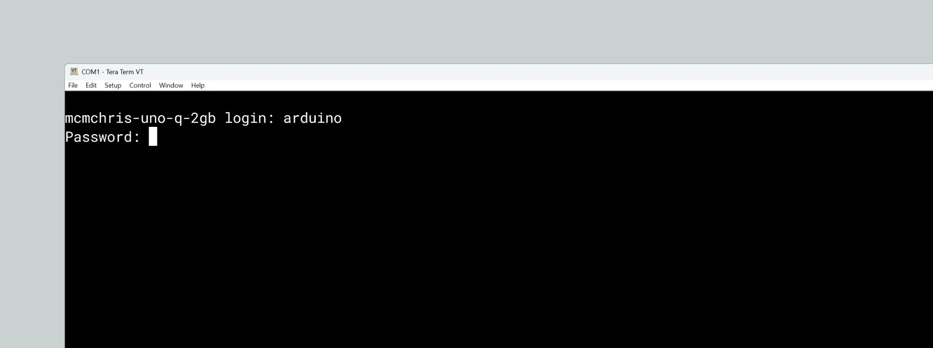
This debug console allows you to view low-level boot logs output by bootloaders such as SPL and U-Boot, which are typically not accessible via high-level interfaces like SSH. It is suitable for troubleshooting power negotiation, hardware initialization, and other issues during the early boot phase. You can also log into the system shell for debugging using the Linux account password configured during initialization.
Power Button
UNO Q has a power button that can be used to restart the board. When the button is pressed and held for more than 5 seconds, the Linux portion of the board will restart.
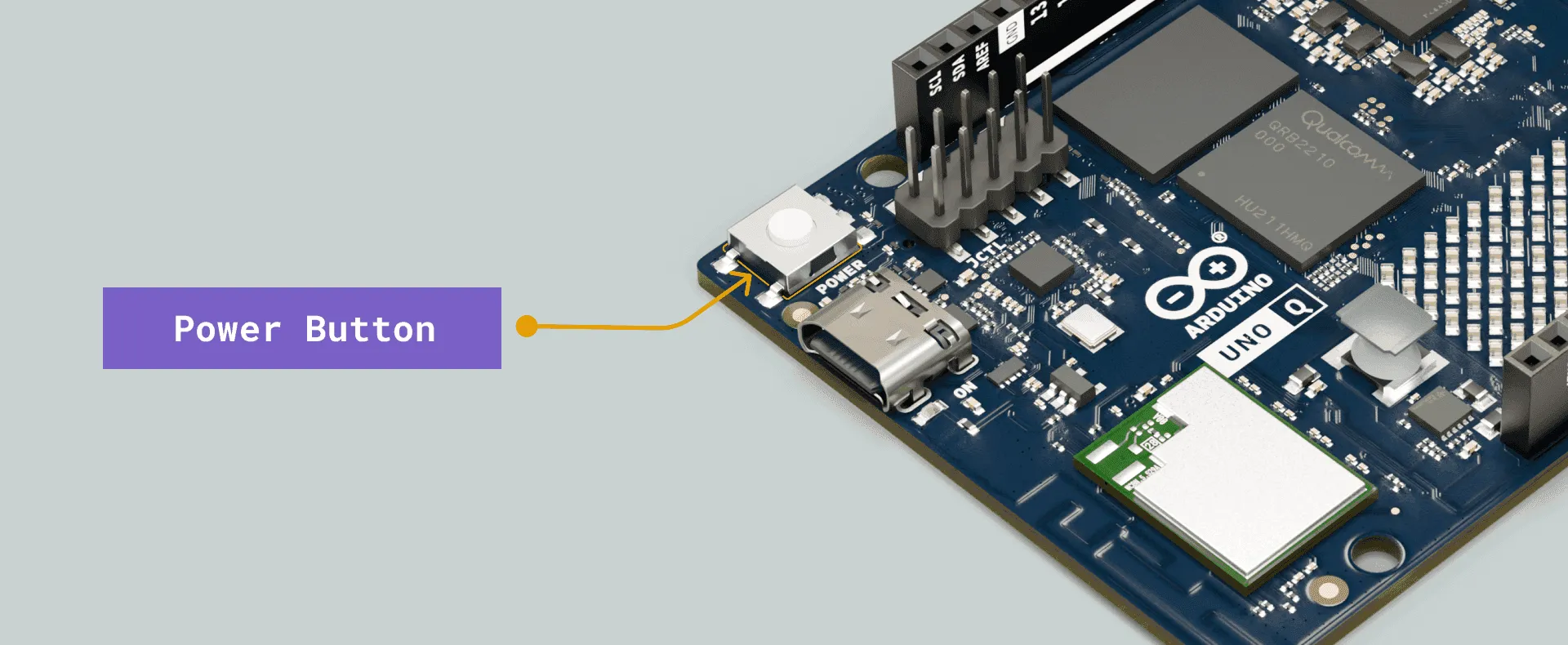
UNO Q will start automatically when powered on; pressing the power button is not required.
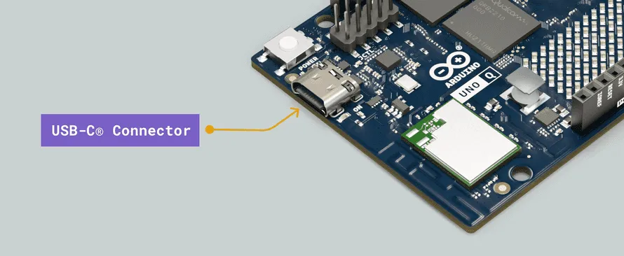
USB-C Connector
Arduino UNO Q is equipped with a USB-C connector, which can be used for power supply, data communication, and video output.
The following table lists the main features of the USB-C connector for expanding UNO Q functionality:
| Feature | Description |
|---|---|
| USB Power Sink | 5V DC / 3A (15W) |
| USB Standard | USB 3.1 Gen 1 (5Gbps) |
| USB-C Display | DisplayPort |
When using a USB-C adapter, dongle, or hub, the following functions can also be expanded:
| Feature | Description |
|---|---|
| Video Out | Supports HDMI output |
| Video In | Supports USB cameras |
| Audio | Supports USB or 3.5mm headphones, including speakers and microphone |
| Ethernet | Supports internet connection via Ethernet |
| HID | Supports USB keyboard, mouse, and other HID devices |
| Storage | Supports external TF cards or USB storage devices |