Hardware Interfaces
Connector Locations
The image below shows the main connectors on the front of the board. The full pinout provides detailed labels and the rear expansion connectors.
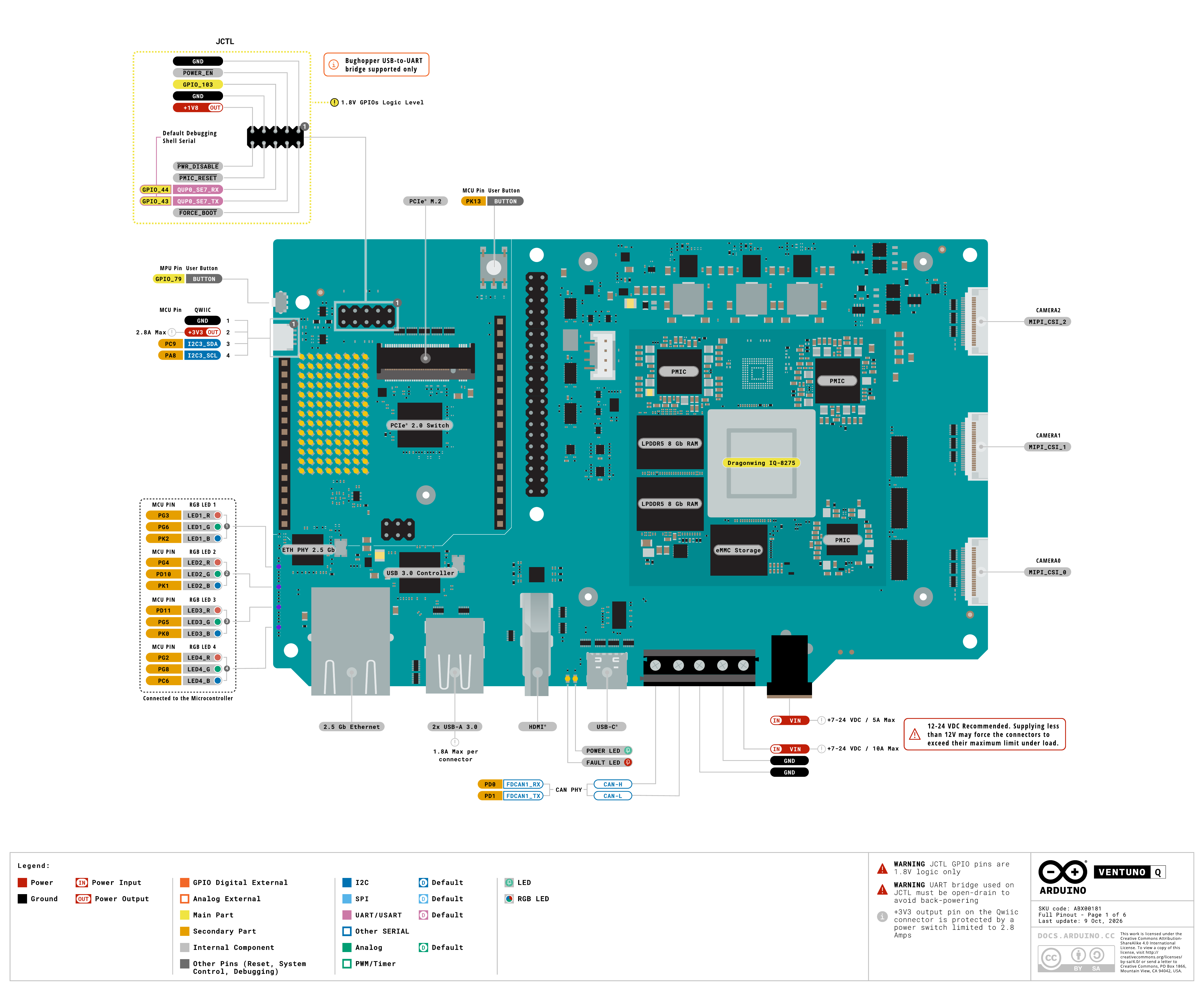
The DC barrel jack voltage label in the pinout diagram differs from the latest manual. For power supply, refer to Power Supply.
External connections
| Connector | Purpose and limitations |
|---|---|
| USB-C | Connect to a computer, dock, or USB peripherals; supports USB PD power input and DisplayPort Alt Mode video output |
| 2 × USB-A | Connect peripherals such as a keyboard, mouse, USB camera, and USB storage; peripheral power consumption counts toward the total power budget |
| HDMI Type-A | Connect an HDMI monitor |
| RJ45 | Wired network, up to 2.5 Gbit/s |
Onboard and expansion connectors
| Connector | Purpose and limitations |
|---|---|
| UNO headers | MCU digital I/O, ADC, DAC, PWM, and communication interfaces |
| Qwiic | MCU I2C expansion, uses Wire1, 3.3 V only |
| 40PIN header | MPU GPIO, I2C, SPI, UART, and I2S expansion interface; signals are level-shifted to 3.3 V |
| M.2 M-key | Install a 2230-format NVMe SSD; SATA M.2 drives are not supported |
| MIPI CSI | 3 onboard camera connectors |
| CAN-FD | Controlled by the MCU; the screw terminal includes a CAN transceiver |
| JMEDIA, JMISC, JOMEGA | High-density expansion connectors; verify the signal and voltage of each pin before wiring |
Pin definitions for JMEDIA, JMISC, and JOMEGA are in the full pinout (pages 5–6), and circuit connections are in the schematics.
Power Supply
| Input connector | Input conditions |
|---|---|
| DC barrel jack | 5.5 × 2.1 mm, 12–24 V DC, connector maximum current 5 A |
| Screw terminal | 7–24 V DC, connector maximum current 10 A |
| USB-C | USB Power Delivery (USB PD) negotiated input, supports 9 V, 15 V, and 20 V, maximum 3 A |
For DC power, a 12 V or 24 V supply is recommended. For high-load use such as AI inference, USB peripherals, or expansion applications, use a power supply rated at no less than 60 W. For example, the DC barrel jack can use a 12 V / 5 A or 24 V / 3 A supply.
In computer connection mode, power the board through the DC barrel jack or screw terminal first, and then connect the computer USB-C data cable. The 5 V from a standard computer USB port cannot serve as the boot power for this board. USB-C standalone power requires USB PD support and negotiation to at least 9 V.
The VIN pin on the UNO headers is protected by a 1.1 A PTC and is not recommended as the main power input when the board runs at full load. For basic use, prefer the DC barrel jack or screw terminal.
UNO Headers and Common Functions
The UNO headers are managed by the STM32 MCU and use 3.3 V logic. A0 and A1 are analog inputs connected directly to the MCU and are not 5 V tolerant. A0–A5 also have digital functions; configure the pins according to the function in use.
| Function | Arduino pin or object |
|---|---|
| Digital input/output | D0–D13, with D14–D19 corresponding to A0–A5 |
| Analog input | A0–A5 |
| Analog output | A0 / DAC0, A1 / DAC1 |
| PWM | D3, D5, D6, D9, D11 |
| UART | D0 / RX, D1 / TX, using Serial1 |
| SPI | D10 / SS, D11 / MOSI, D12 / MISO, D13 / SCK, using SPI |
| UNO header I2C | SDA (PH12), SCL (PH11), using Wire |
Arduino pin names, STM32 port names, and Linux GPIO numbers belong to different numbering systems. D4 in an example should be connected to D4 on the UNO headers, not to GPIO4 as on other platforms. For basic operations, see App Lab basic function examples.
I2C and Qwiic
| Connection location | Object and signals used |
|---|---|
| UNO headers | Wire; SDA corresponds to PH12, SCL corresponds to PH11 |
| Qwiic connector | Wire1; SDA corresponds to PC9, SCL corresponds to PA8; also provides 3.3 V and GND |
The I2C on Qwiic and on the UNO headers are not the same connection entry point. After connecting a Qwiic sensor, use Wire1 or confirm that the library in use allows selecting that object; do not merely change the sensor address.
Qwiic supports 3.3 V only. When connecting other I2C modules, confirm the module's power supply, pull-up voltage, and address.
A4 and A5 do not provide hardware I2C functionality; UNO Shields that use hardware I2C need to connect to the dedicated SDA and SCL pins.
CSI Camera
The board provides three 22PIN, 0.5 mm pitch MIPI CSI connectors: Camera 0 (J3_2), Camera 1 (J3_3), and Camera 2 (J3_1). For connector locations and pin definitions, see the full pinout.
Connecting the Camera
The image below uses the Arducam IMX577 Mini Camera Module for Qualcomm RB3G2 (B0488) as an example to show how to connect the camera to the board's CSI connector.
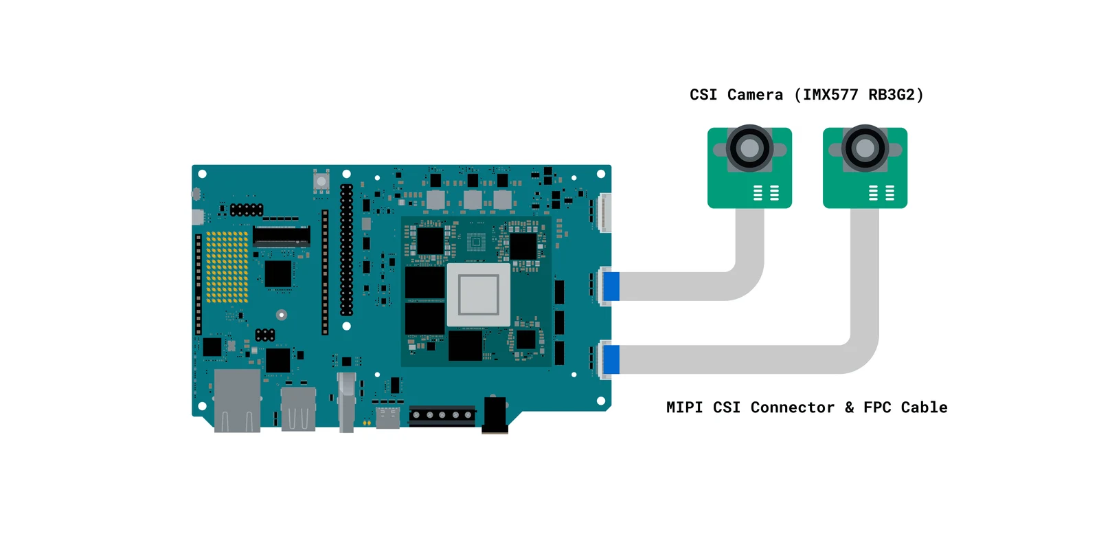
- Turn off the board and disconnect power before connecting the camera cable.
- Confirm that the cable's connector specification, pin definitions, and contact orientation match the board and the camera, and insert the cable fully into the connector.
- Connect power and start the board. The onboard camera connectors are probed during boot; there is no need to enable the UNO Media Carrier on the Carriers page in App Lab.
Onboard LEDs and Buttons
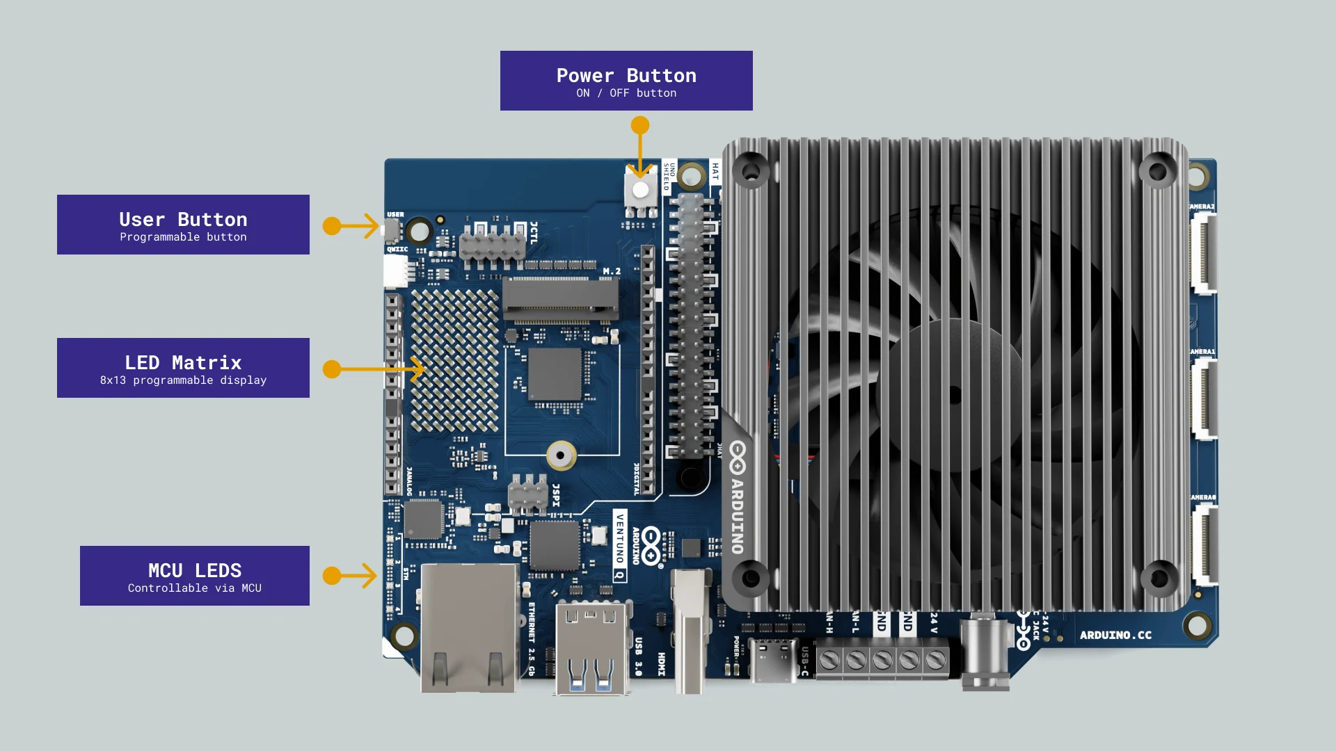
| Component | Control method |
|---|---|
| 8 × 13 blue LED matrix | Controlled by the MCU, using Arduino_LED_Matrix |
| 4 RGB LED groups | Controlled by the MCU, LED1_R–LED4_B; active-low |
| User button | Connected to MPU GPIO_79, accessed from the Linux side |
| Power button | In SSH / ADB mode, long-press for more than 10 seconds to turn the board off; to boot again, disconnect and reconnect power |
The board boots automatically once power is connected. The User button is not one of the Arduino button pins on the UNO headers, so it cannot be read directly using button constants from other boards.
RGB LED
The following two onboard examples require no external components. In App Lab, create a new App for each, write the code into sketch/sketch.ino, and click "Run". For how to create an application, see App Lab usage instructions.
All four RGB LED groups are active-low: LOW turns the corresponding color on, and HIGH turns it off.
| LED group | Red, green, and blue color constants |
|---|---|
| LED1 | LED1_R, LED1_G, LED1_B |
| LED2 | LED2_R, LED2_G, LED2_B |
| LED3 | LED3_R, LED3_G, LED3_B |
| LED4 | LED4_R, LED4_G, LED4_B |
The following example uses LED3 to show red, green, and blue in sequence, with each color shown for about 1 second.
const int colors[] = {LED3_R, LED3_G, LED3_B};

void setup() {
  for (int i = 0; i < 3; i++) {
    pinMode(colors[i], OUTPUT);
    digitalWrite(colors[i], HIGH);
  }
}

void loop() {
  for (int i = 0; i < 3; i++) {
    digitalWrite(colors[i], LOW);
    delay(1000);
    digitalWrite(colors[i], HIGH);
  }
}
To control another LED group, replace the color constants in the code with the constants for that group.
LED Matrix
The onboard matrix has 8 rows and 13 columns and is controlled by the MCU. Use the Arduino_LED_Matrix library provided with the core: set the bit depth, then display a pixel array with draw().
#include <Arduino_LED_Matrix.h>

Arduino_LED_Matrix matrix;
uint8_t frame[8 * 13] = {0};

void setup() {
  matrix.begin();
  matrix.setGrayscaleBits(1);
  for (int row = 0; row < 8; row++) {
    frame[row * 13 + 2] = 1;
    frame[row * 13 + 10] = 1;
  }
  matrix.draw(frame);
}

void loop() {
}
The expected output is two vertical lines. This example uses 1-bit pixels: 0 is off and 1 is on; the array has 104 elements arranged by row. Adjust the array to change the pattern.
For grayscale display, use matrix.setGrayscaleBits(3) to set 3-bit pixels, corresponding to 8 brightness levels from 0 to 7, and adjust the pixel values in the array to that range.
Expansion Connector Notes
- USB-C supports DisplayPort Alt Mode; when this mode is enabled, USB-C data transfer drops to USB 2.0.
- The 40PIN header connects to the MPU, and its signals are level-shifted to 3.3 V; it also provides 3.3 V and 5 V power pins.
- When Bluetooth is enabled, physical pins 8, 10, 11, and 36 of the 40PIN header are occupied by the wireless module UART and cannot be used by an external HAT at the same time.
- Before installing an M.2 module, cable, or expansion board, turn off the board and disconnect power. The M.2 connector is only for 2230-format NVMe storage expansion; SATA M.2 drives are not supported, and it cannot be used as a boot drive.
- JCTL is the MPU debug interface and includes different voltage domains; the UART signal is 1.8 V. Use the Arduino Bughopper for debugging and wire it according to the pinout to avoid applying incorrect voltages or back-powering through the serial port.