Serial Tool Usage
This tutorial uses the CF12-6 Servo and the bus servo driver board Bus Servo Adapter (A) as an example to introduce how to control the servo by sending command frames through a serial assistant.
Wiring Steps
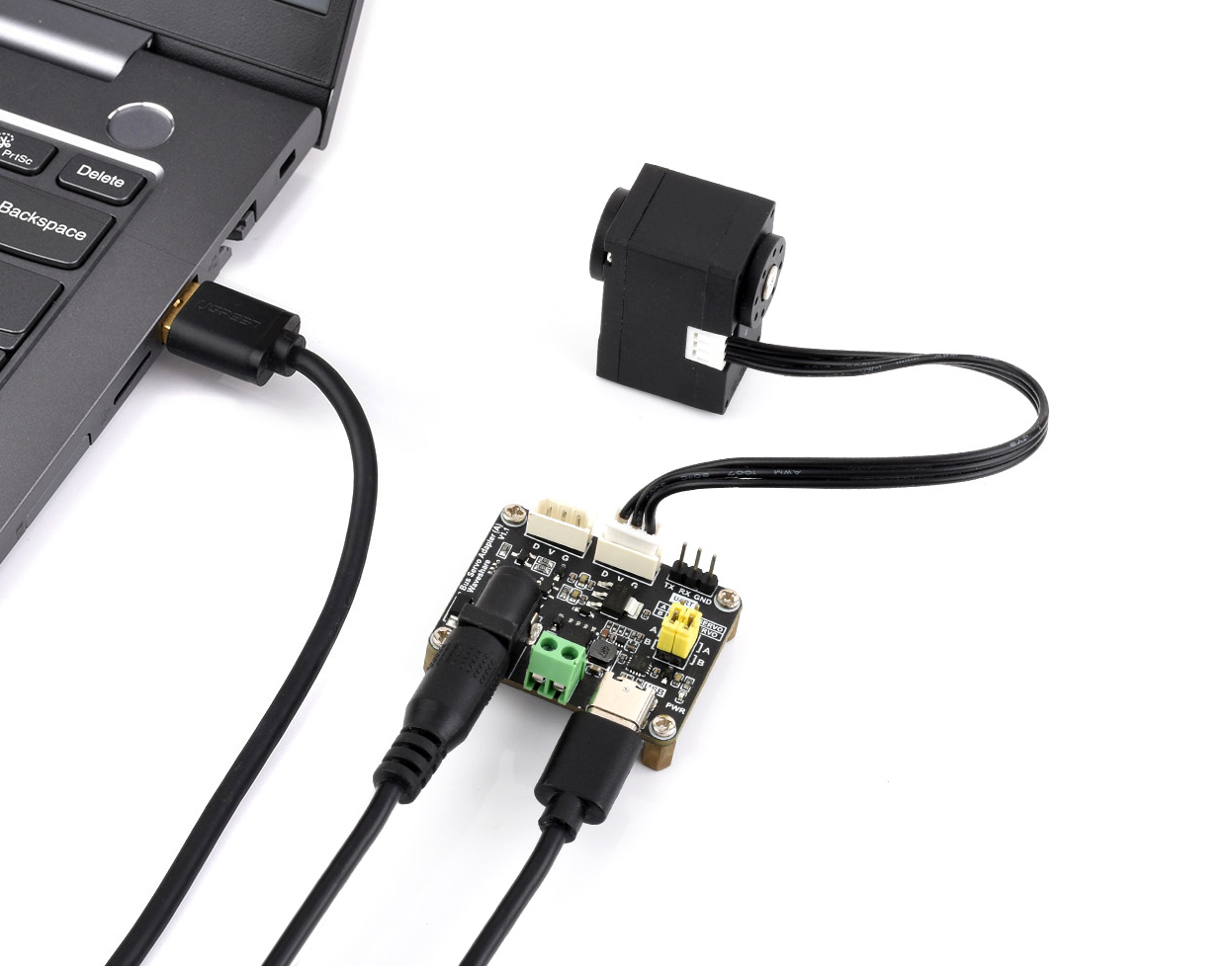
- Connect the CF12-6 Servo to the bus servo interface on the Bus Servo Adapter (A).
- Connect the Bus Servo Adapter (A) to the computer using a USB Type-C data cable. Check that the jumper cap on the Bus Servo Adapter (A) is in the B position.
- Connect a power supply that meets the operating voltage requirements of the CF12-6 Servo to the DC5521 socket or the green power terminal block. (USB Type-C is only responsible for serial communication and cannot replace the servo power input)
- Open Windows "Device Manager" and check the newly added COM port under "Ports (COM & LPT)".
Serial Assistant Settings
Open the serial debugging assistant, select the device serial port, choose 1000000 as the baud rate, and check "HEXShow", "SendHEX", and "Show Time and Packet". After opening the serial port, you can send commands to the servo.
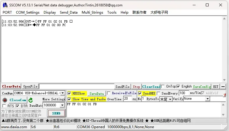
The default baud rate for CF series servos is 1000000. If the servo baud rate has been modified, the baud rate of the serial assistant needs to match the servo's current baud rate.
Common Command Frame Examples
Write command frames to control the servo according to the servo communication protocol and memory table explanation.
Servo Communication Protocol
View the servo communication protocol, data format, and command descriptions.
CF Servo Memory Table Explanation
View the CF servo memory table addresses, parameter meanings, and configuration descriptions.
1. Ping command. Check the connectivity and working status of the servo with ID1.
FF FF 01 02 01 FB
2. Read the current position of the servo with ID1
FF FF 01 04 02 38 02 BE
3. Change the servo ID
Change the servo with ID 01 to 02. The memory table EPROM has a protection lock switch. If you want the modified ID to be saved after power-off, you need to turn off the write lock first; if you do not require the modified ID to be saved after power-off, simply send the command to change the servo ID to 2.
① Unlock the EPROM for the servo with ID1:
FF FF 01 04 03 37 00 C0
② Change the servo ID to 2:
FF FF 01 04 03 05 02 F0
③ Use the PING command to confirm whether the returned ID is 2:
FF FF 02 02 01 FA
4. Control servo motion
① Control the servo with ID1 to rotate to position 0 at a speed of 1000 and a current of 100 * 6.5mA.
FF FF 01 09 03 2A 00 00 64 00 E8 03 79
② Control the servo with ID1 to rotate to position 2048 at a speed of 1000 and a current of 100 * 6.5mA.
FF FF 01 09 03 2A 00 08 64 00 E8 03 71
③ Control the servo with ID1 to rotate to position 4095 at a speed of 1000 and a current of 100 * 6.5mA.
FF FF 01 09 03 2A FF 0F 64 00 E8 03 6B
5. Enable the torque lock for the servo with ID1
FF FF 01 04 03 28 01 CE
6. Disable the torque lock for the servo with ID1
FF FF 01 04 03 28 00 CF