CM5-DUAL-ETH-BOX-B

The CM5-DUAL-ETH-BOX-B is a carrier board designed for use with the Raspberry Pi Compute Module 5. It offers powerful features, including onboard 1x USB 3.2 Gen1, 1x USB 2.0, an M.2 M-Key slot, a 40PIN GPIO header, and dual Ethernet ports.
| SKU | Product |
|---|---|
| 34180 | CM5-DUAL-ETH-BOX-B |
Features
- Do not plug or unplug any devices other than USB and HDMI while the system is powered on
- The Type-C port can be used as a USB SLAVE interface for flashing images or powering the device
- Onboard 2 USB ports, with a total maximum current output of 2A (1x USB 3.2 Gen1 + 1x USB 2.0 port)
- Supports triple independent displays. When a MIPI DSI driver is added, the system will default to connecting to it regardless of whether a screen is connected, and the screen will display in split-screen mode (depending on the system version)
- Onboard M.2 M KEY interface, supports NVMe SSD protocol (or PCIe protocol AI modules)
- Onboard BOOT switch: Before powering on, slide the BOOT switch to ON and connect via Type-C to a computer to put the device into flashing mode
- When flashing via Type-C, do not connect other devices; otherwise, insufficient power may prevent the device from being recognized
Onboard Resources
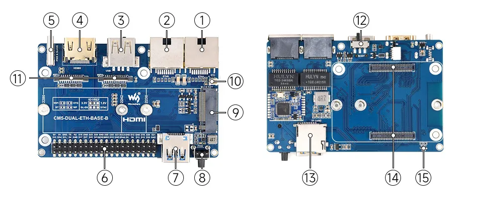
1. RJ45 2500M Ethernet Port
Supports 10M / 100M / 1000M / 2500M network connections
2. RJ45 1000M Ethernet Port
Supports 10M / 100M / 1000M network connections
3. USB 2.0 Port
Standard USB 2.0 port
4. HDMI Interface
Supports 4K output
5. Type-C Power Port
DC 5V power input, or used for eMMC flashing
6. 40PIN GPIO Header
Suitable for connecting to various HAT / HAT+ modules
7. USB 3.2 Gen1 Port
Supports up to 5 Gbps read / write speed
8. PSW Button
Long press to force power off, short press for soft shutdown or power on
9. M.2 M KEY
Supports 2230 / 2242 / 2280 NVMe SSDs or AI modules
10. RTC Battery Header
SH1.0 socket for external RTC battery to maintain real-time clock operation
11. MIPI Interface
Supports connecting DSI displays or CSI cameras
12. BOOT Button
Convenient for entering flashing mode
13. TF Card Slot
For connecting a TF card with an OS system (Applicable only for CM5 versions without eMMC)
14. CM5 Socket
Compatible with all versions of Compute Module 5
15. STAT LED
Dual-color status LED
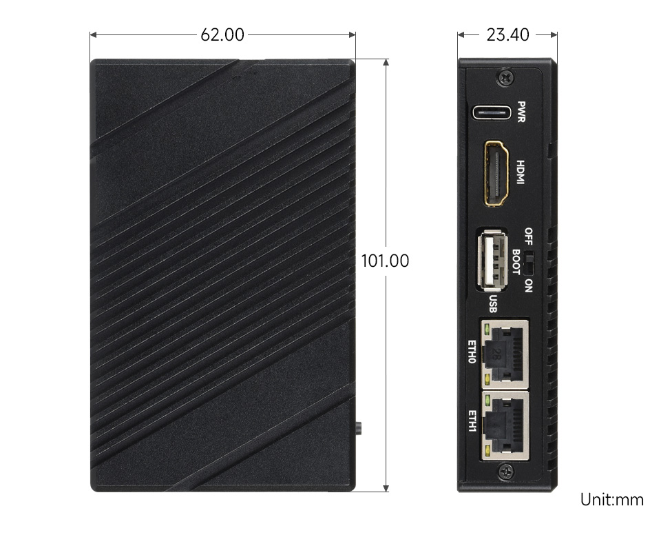
Dimensions
Development Related
Image Flashing
- Entering Download Mode Onboard BOOT Switch: Slide the BOOT switch to ON before powering on, connect to PC via Type-C
- Flashing Images for LITE Versions: LITE Version Tutorial
- Flashing Images for EMMC Versions: EMMC Version Tutorial
NVMe(M.2 M KEY)
- The product supports all features in this tutorial: NVMe Usage Tutorial
- Includes: Formatting Hard Drive | Hard Drive Partitioning | Manual Mounting | Auto-mount on Boot | Read/Write Test
NVMe SSD Boot
- First, boot the Raspberry Pi using a TF card, mount and test the NVMe SSD to ensure the hardware functions correctly
- NVMe SSD Boot: Boot Configuration Tutorial
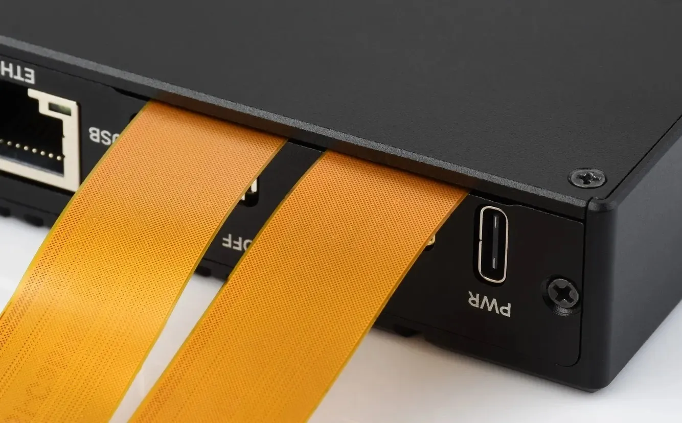
MIPI
- There is a gap between the top cover and the side cover of the enclosure, allowing the MIPI cable to be routed out through this gap
- You can add specific content to config.txt to select using DSI or CSI connection
- MIPI - DSI
- The product supports all features in this tutorial: DSI Interface Usage Tutorial
- DSI includes: DSI Interface Selection
- MIPI - CSI
- The product supports all features in this tutorial: CSI Interface Usage Tutorial - CSI includes: CSI Interface Selection (Driver Settings) | Camera Detection | Displaying Real-time Preview | Taking a Photo | Recording a Video
Fan Control
- The product supports all features in this tutorial: Fan Usage Tutorial
- Includes: Manual Speed Control | View Current Speed | Restore Automatic Temperature Control
RTC
- With an RTC battery connected, the product supports all features in this tutorial: RTC Usage Tutorial
- Includes: Get RTC Time | Set RTC Time | Synchronize RTC Clock | Scheduled Shutdown | Scheduled Power-on - Low Power Wake-up | RTC Battery Charging