CM5-ETH-RS485-4G-BASE
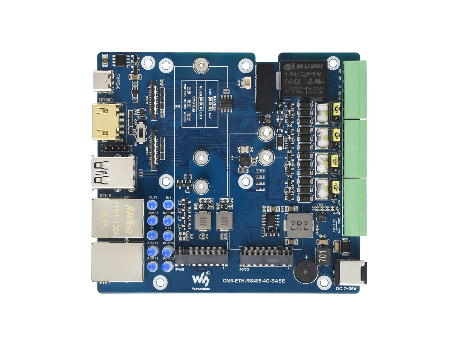
The CM5-ETH-RS485-4G-BASE is a base board for the Raspberry Pi Compute Module 5. It offers powerful features, including 1x USB 3.2 Gen1, 1x USB2.0, M.2 M KEY, M.2 B KEY (for 4G/5G modules), and dual Ethernet ports, with additional GPIO-expanded RS485, digital input, and relay for user convenience.
| SKU | Product |
|---|---|
| 34251 | CM5-ETH-RS485-4G-BASE |
| 34402 | CM5-ETH-RS485-4G-BOX (US) |
| 34403 | CM5-ETH-RS485-4G-BOX (EU) |
| 34404 | CM5-ETH-RS485-4G-BOX (UK) |
Version Options
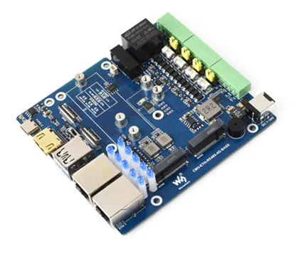
Dual Gigabit Ethernet CM5 Expansion Board
(Base board)
(Base board)

Dual Gigabit Ethernet CM5 Host
(Base board + metal case)
(Base board + metal case)
Features
- Do not plug or unplug any devices other than USB and HDMI while the system is powered on
- The Type-C port can be used as a USB SLAVE interface for flashing images or powering the device
- Onboard 1 USB port group with a total maximum output current of 2A (1x USB 3.2 Gen1 + 1x USB 2.0 port)
- Supports triple independent displays. When a MIPI DSI driver is added, the system will default to connecting to it regardless of whether a screen is connected, and the screen will display in split-screen mode (depending on the system version)
- Onboard M.2 M KEY interface, supports NVMe SSD (or PCIe-based AI modules)
- Onboard M.2 B KEY interface, supports 4G/5G communication modules
- 4 isolated RS485 channels + 1 isolated digital input + 1 isolated relay (fully isolated)
- Onboard encryption chip and single controllable buzzer
- Onboard BOOT button: Press and hold the BOOT button before powering on, then connect to a PC via Type-C to enter flashing mode
- When using Type-C for programming, do not connect any other devices, otherwise insufficient power may prevent the device from being recognized
Onboard Resources
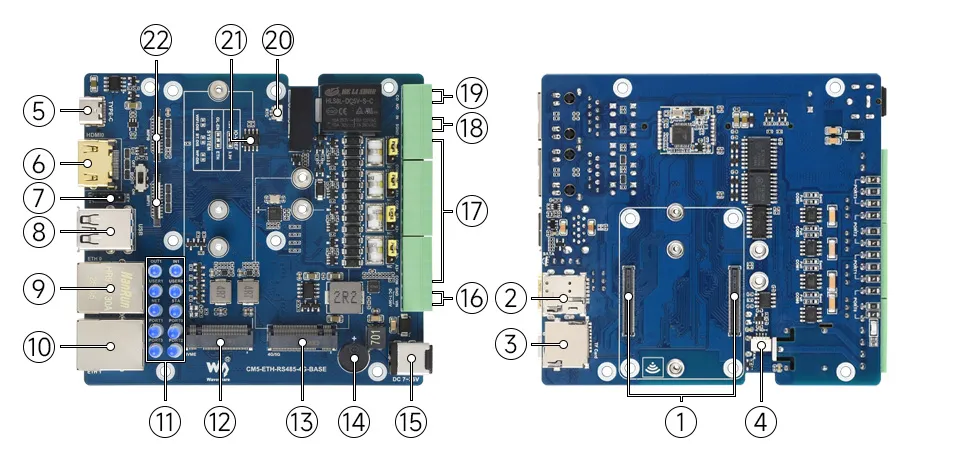
1. CM5 Socket
Compatible with all versions of Compute Module 5
2. Nano SIM Card Slot
3. TF Card Slot
For connecting a TF card with an OS system (Applicable only for CM5 versions without eMMC)
4. Fan Interface
5V 4PIN JST-SH PWM fan connector for connecting a cooling fan
5. Flashing Interface
Used for eMMC flashing or USB OTG
6. HDMI Interface
Supports 4K output
7. Button & LED Expansion Interface
8. Dual USB Ports
One standard USB 2.0 port and one USB 3.2 Gen1 port (USB 3.2 Gen1 supports up to 5Gbps)
9. 1000M Ethernet Port
RJ45 1000M port, supports 10M / 100M / 1000M network connections
10. 2500M Ethernet Port
RJ45 2500M port, supports 10M / 100M / 1000M / 2500M network connections
11. Indicator LEDs
Status LEDs for various interfaces, plus two extra user-configurable LEDs
12. M.2 M KEY
Supports 2242 / 2230 / 2280 NVMe SSDs or AI modules
13. M.2 B KEY
Supports 4G / 5G communication modules
14. Buzzer
15. DC Power Supply Jack
Supports DC 7V ~ 36V power input (do not connect power simultaneously with the screw terminal)
16. DC Power Screw Terminal
Supports DC 7V ~ 36V power input (do not connect power simultaneously with the DC power supply jack)
17. RS485 Interfaces
18. Digital Input Interface
Input voltage: 5V ~ 36V
19. Relay Interface
Contact rating: ≤ 10A 250V AC or ≤ 10A 30V DC
20. RTC Battery Header
Accepts a compatible RTC battery to power the RTC
21. Encryption Chip
22. Dual MIPI Interfaces
Supports connecting DSI displays or CSI cameras. The case only has a cutout for MIPI0; MIPI1 cannot be routed outside the case.
23. BOOT Button
Set to ON before power-up; the board will enter programming mode on power-up
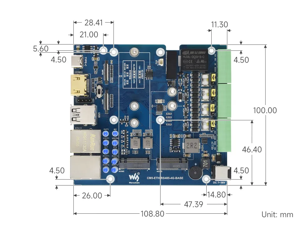
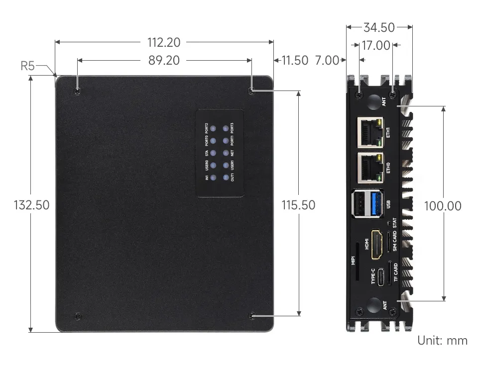
Dimensions
Development Resources
Image Flashing
- Entering Download Mode
- Onboard BOOT switch: slide the BOOT switch to ON before power-up, then connect the board to a computer via Type-C; it will enter programming mode
- Flashing Images for LITE Versions: LITE Version Tutorial
- Flashing Images for EMMC Versions: EMMC Version Tutorial
NVMe(M.2 M KEY)
- The product supports all features in this tutorial: NVMe Usage Tutorial
- Includes: Formatting the Hard Drive | Hard Drive Partitioning | Manual Mounting | Auto-mount on Boot | Read/Write Test
NVMe SSD Boot
- First, boot the Raspberry Pi using a TF card, mount and test the NVMe SSD to ensure the hardware functions correctly
- NVMe SSD Boot: Boot Configuration Tutorial
MIPI
warning
The case only has a cutout for MIPI0; MIPI1 cannot be routed outside the case. MIPI1 can only be used when the case is not assembled.
- You can add specific content to config.txt to select using DSI or CSI connection
- MIPI - DSI
- The product supports all features in this tutorial: DSI Interface Usage Tutorial
- DSI includes: DSI Interface Selection
- MIPI - CSI
- The product supports all features in this tutorial: CSI Interface Usage Tutorial
- CSI includes: CSI Interface Selection (Driver Settings) | Camera Detection | Displaying Real-time Preview | Taking a Photo | Recording a Video
Fan Control
warning
The product does not include a fan; only a fan connector is provided on the carrier board.
- The product supports all features in this tutorial: Fan Usage Tutorial
- Includes: Manual Speed Control | View Current Speed | Restore Automatic Temperature Control
RTC
- With an RTC battery connected, the product supports all features in this tutorial: RTC Usage Tutorial
- Includes: Get RTC Time | Set RTC Time | Synchronize RTC Clock | Scheduled Shutdown | Scheduled Power-on - Low Power Wake-up | RTC Battery Charging
RS485
- The product has 4 isolated RS485 interfaces
- The product supports all features in this tutorial: RS485 Usage Tutorial
Digital Input Interface
warning
The maximum input voltage supported by the product's digital input interface is 36V.
| Control Pin | Function | Description |
|---|---|---|
| GPIO24 | IN1 | Digital Input Channel 1 |
- When the digital input is high (above 2V), the GPIO reads as low
- When the digital input is low (below 0.9V), the GPIO reads as high
Relay
| Control Pin | Function | Description |
|---|---|---|
| GPIO25 | Relay | Normally-open (NO) and common (COM) terminals are brought out by default |
- When the GPIO outputs high, the relay is activated (NO and COM are connected)
- When the GPIO outputs low, the relay is deactivated (NO and COM are disconnected)
4G/5G
- The product has an onboard M.2 B KEY interface, supporting 4G / 5G communication modules.
- The product supports all features in this tutorial: 4G / 5G Usage Guide
Encryption Chip (ATSHA204)
- I2C address of this product's encryption chip (ATSHA204): 0x64
- The default I2C used by this product's encryption chip (ATSHA204) is: I2C1 (SDA:GPIO2, SCL:GPIO3)
- The product supports all features in this tutorial: ATSHA204 Usage Tutorial
- Includes: Data Read/Write | Chip Configuration Area Description
Buzzer
| Control Pin | Function | Description |
|---|---|---|
| GPIO22 | Buzzer | Active buzzer |
- When the GPIO outputs high, the buzzer is silent.
- When the GPIO outputs low, the buzzer sounds.
LED Indicators
| LED Label | Function | Description |
|---|---|---|
| IN1 | Digital Input LED | When the input is high (above 2V), the LED is off |
| OUT1 | Relay status LED | When the relay is activated (NO and COM connected), the LED lights up |
| USER0 | User-definable LED 0 | Connected to GPIO20, active low |
| USER1 | User-definable LED 1 | Connected to GPIO26, active low |
| STA | 4G/5G module enable LED | 4G/5G module interface LEDs |
| NET | 4G/5G module status LED | |
| PORT0 | RS485 CH0 communication LED | Flashes when RS485 communication is active |
| PORT1 | RS485 CH1 communication LED | |
| PORT2 | RS485 CH2 communication LED | |
| PORT3 | RS485 CH3 communication LED |