CM5-HMI-7A-ACCE
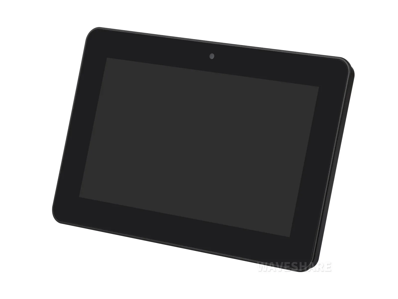
The CM5-HMI-7A-ACCE is a 7-inch industrial HMI touch display development board designed for use with the Raspberry Pi Compute Module 5. It features a 720 × 1280 IPS optical bonding capacitive touchscreen and a 5-megapixel front camera. The product uses a black aluminum alloy case, includes an onboard supercapacitor module with power-loss protection, and supports industrial communication and networking options such as RS485, 4G / 5G, and Gigabit Ethernet. The package does not include the CM5 core board.
Version Options
| SKU | Model | Screen Size | Resolution | Viewing Angle |
|---|---|---|---|---|
| 35718 | CM5-HMI-7A-ACCE (US) | 7inch | 720 × 1280 | 170° |
| 35719 | CM5-HMI-7A-ACCE (EU) | 7inch | 720 × 1280 | 170° |
| 35720 | CM5-HMI-7A-ACCE (UK) | 7inch | 720 × 1280 | 170° |
| 35721 | CM5-HMI-8A-ACCE (US) | 8inch | 800 × 1280 | 178° |
| 35722 | CM5-HMI-8A-ACCE (EU) | 8inch | 800 × 1280 | 178° |
| 35723 | CM5-HMI-8A-ACCE (UK) | 8inch | 800 × 1280 | 178° |
| 35724 | CM5-HMI-10.1A-ACCE (US) | 10.1inch | 800 × 1280 | 178° |
| 35725 | CM5-HMI-10.1A-ACCE (EU) | 10.1inch | 800 × 1280 | 178° |
| 35726 | CM5-HMI-10.1A-ACCE (UK) | 10.1inch | 800 × 1280 | 178° |
Features
- Available in 7inch, 8inch, and 10.1inch screen versions, equipped with a 5-megapixel front camera
- Do not plug or unplug any devices other than USB and HDMI while the system is powered on
- The Type-C port can be used as a USB SLAVE interface for flashing images or powering the device
- Onboard M.2 M KEY interface, supports NVMe SSD (or PCIe‑based AI modules)
- Onboard M.2 B KEY interface, supports 4G/5G communication modules
- Optional versions: 2x RS485 + 2x RS232, or 4x RS485 (isolated)
- 1x CAN supporting 1Mbps communication rate (isolated)
- 2x Digital Output + 2x Digital Input (isolated)
- 2x ADC analog input (4 - 20mA current acquisition can be achieved by desoldering components)
- Single controllable buzzer
- Onboard EEPROM and encryption chip
- Onboard BOOT button: Press and hold the BOOT button before powering on, then connect to a PC via Type-C to enter flashing mode
- When using Type-C for flashing, do not connect other devices; otherwise, insufficient power may cause the device not to be recognized
- Onboard supercapacitor module, supporting power-loss protection
Onboard Resources
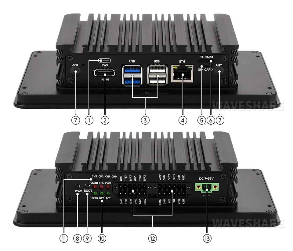
- Type-C portFor power supply, eMMC flashing, or USB OTG
- HDMI portSupports 4K output
- USB ports2 × USB 2.0 and 2 × USB 3.2 Gen1; USB 3.2 Gen1 supports up to 5 Gbps
- 1000M Ethernet portRJ45 port, supporting 10M, 100M, and 1000M network access
- Nano SIM card slot
- TF card slotFor connecting a TF card with an OS; only applicable to CM5 versions without eMMC
- External antenna mounting holes
- PSW buttonLong press to force power off, short press to soft power off or on
- BOOT buttonPress before powering on to enter flashing mode
- System function indicators
- Serial communication indicators
- Multi-function interfacesMulti-function interface expanded via GPIO
- DC power supply screw terminalSupports 7-36 V DC power supply
Dimensions
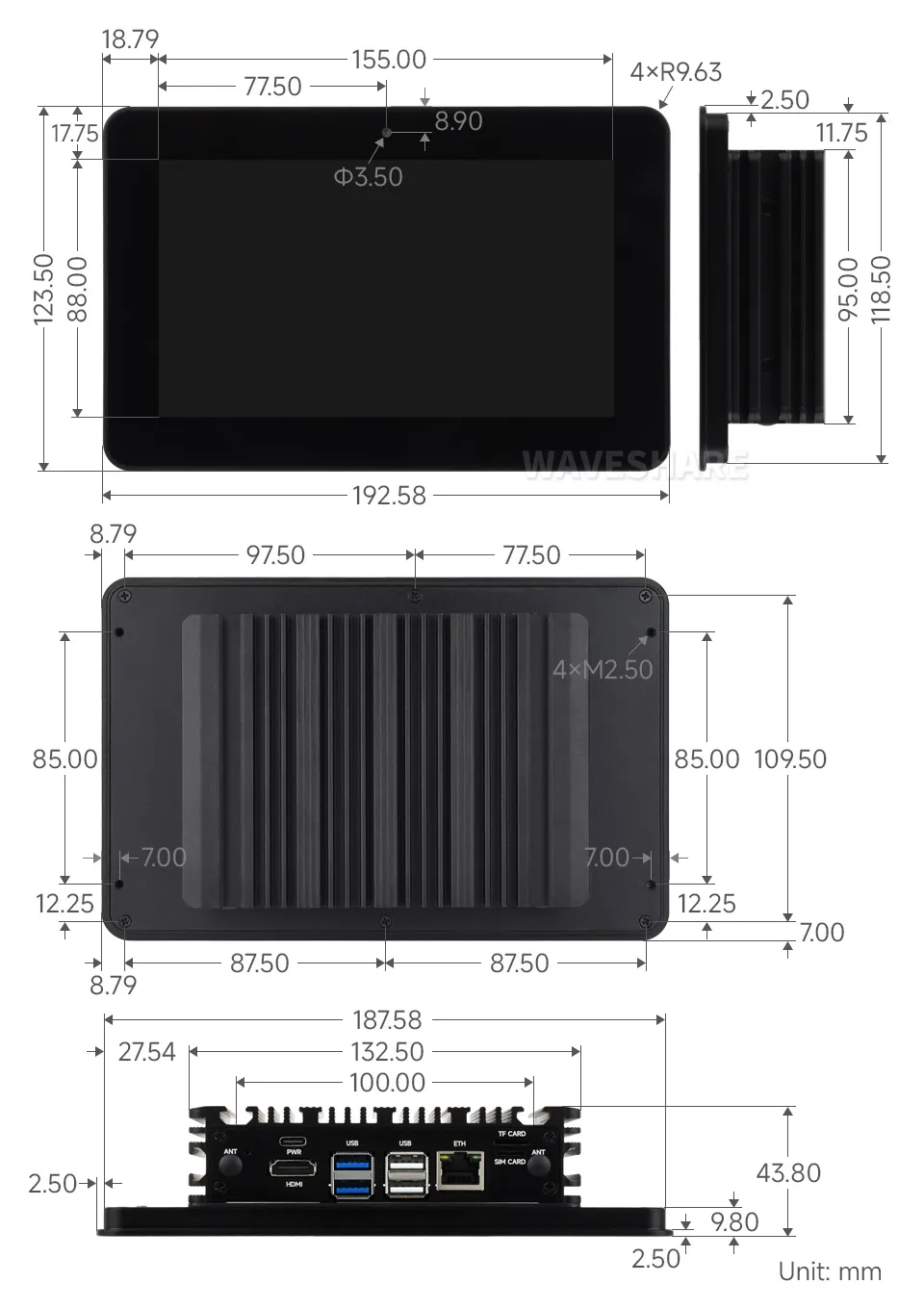
The figure below shows the external dimensions of the CM5-HMI-7A-ACCE (7inch screen version).
Development Resources
Display and Camera Usage
- The CM5-HMI-xA-ACCE series is available in 7inch, 8inch, and 10.1inch screen versions, all equipped with a 5-megapixel front camera. Different screen sizes use different DSI configurations, and the camera uses OV5647.
- The product supports all features in the following guide: Screen and Camera Usage
Image Flashing
- Entering download mode
- Onboard BOOT Button: Press and hold the BOOT button before powering on, connect to PC via Type-C, and release the button after the power indicator lights up
- Flashing Images for LITE Versions: LITE Version Tutorial
- Flashing Images for EMMC Versions: EMMC Version Tutorial
NVMe(M.2 M KEY)
- The product supports all features in this tutorial: NVMe Usage Tutorial
- Includes: Formatting the Hard Drive | Hard Drive Partitioning | Manual Mounting | Auto-mount on Boot | Read/Write Test
NVMe SSD Boot
- First, boot the Raspberry Pi using a TF card, mount and test the NVMe SSD to ensure the hardware functions correctly
- NVMe SSD Boot: Boot Configuration Tutorial
MIPI
- You can add specific content to config.txt to select using DSI or CSI connection
- MIPI - DSI
- The product supports all features in this tutorial: DSI Interface Usage Tutorial
- DSI includes: DSI Interface Selection
- MIPI - CSI
- The product supports all features in this tutorial: CSI Interface Usage Tutorial
- CSI includes: CSI Interface Selection (Driver Settings) | Camera Detection | Displaying Real-time Preview | Taking a Photo | Recording a Video
Fan Control
The product does not include a fan; only a fan connector is provided on the carrier board.
- The product supports all features in this tutorial: Fan Usage Tutorial
- Includes: Manual Speed Control | View Current Speed | Restore Automatic Temperature Control
RTC
- With an RTC battery connected, the product supports all features in this tutorial: RTC Usage Tutorial
- Includes: Get RTC Time | Set RTC Time | Synchronize RTC Clock | Scheduled Shutdown | Scheduled Power-on - Low Power Wake-up | RTC Battery Charging
RS485/RS232
- The product features onboard RS485/RS232 interfaces (Version A does not have RS232)
- The product supports all features in this tutorial: RS485/RS232 Usage Tutorial
CAN
- The product has an onboard CAN interface (supports up to 1Mbps).
- The product supports all features in this tutorial: CAN Usage Guide
Analog Input Interface
The product's analog input interface is implemented via the SGM58031XMS10G, expanded through I2C1.
- The I2C address of the analog acquisition chip (SGM58031XMS10G) on this product: 0x48
- The default I2C connection for the chip is: I2C1 (SDA:GPIO2, SCL:GPIO3) I2C1 (SDA:GPIO2, SCL:GPIO3)
Digital Input Interface
The maximum input voltage supported by the product's digital input interface is 36V.
| Control Pin | Function | Description |
|---|---|---|
| GPIO23 | IN1 | Digital Input Channel 1 |
| GPIO24 | IN2 | Digital Input Channel 2 |
- When the digital input is high (above 2V), the GPIO reads as low
- When the digital input is low (below 0.9V), the GPIO reads as high
Digital Output Interface
The product's digital output is open-drain, with a maximum cut-off voltage of 150V and a maximum current of 500mA (on-resistance is 18Ω). Overvoltage or overcurrent will damage the device.
| Control Pin | Function | Description |
|---|---|---|
| GPIO27 | OUT1 | Digital Output Channel 1 |
| GPIO22 | OUT2 | Digital Output Channel 2 |
- When the GPIO outputs high, the digital output level is low
- When the GPIO outputs low, the digital output level is high-impedance
4G/5G
- The product has an onboard M.2 B KEY interface, supporting 4G / 5G communication modules.
- The product supports all features in this tutorial: 4G / 5G Usage Guide
Encryption Chip (ATSHA204)
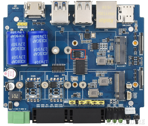
- I2C address of this product's encryption chip (ATSHA204): 0x64
- The default I2C used by this product's encryption chip (ATSHA204) is: I2C1 (SDA:GPIO2, SCL:GPIO3)
- The product supports all features in this tutorial: ATSHA204 Usage Tutorial
- Includes: Data Read/Write | Chip Configuration Area Description
EEPROM (CAT24C32)
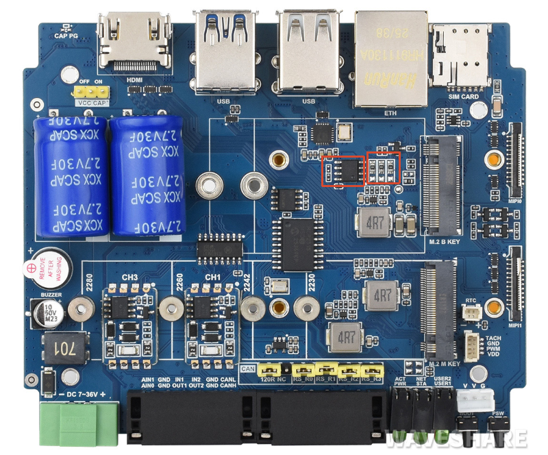
- I2C address of the chip: 0x50 (adjustable by changing the soldering position of resistors A0~A2)
- The default I2C connection for the chip is: I2C1 (SDA:GPIO2, SCL:GPIO3) I2C1 (SDA:GPIO2, SCL:GPIO3)
Power-Loss Protection
- The product's power-loss protection only takes effect when using 7-36V power supply, with capacitor charging enabled and the capacitor fully charged.
- After the power-loss protection function is enabled, the supercapacitor will provide additional power to the device for a period of time when the external power is lost, giving the user time to back up data.
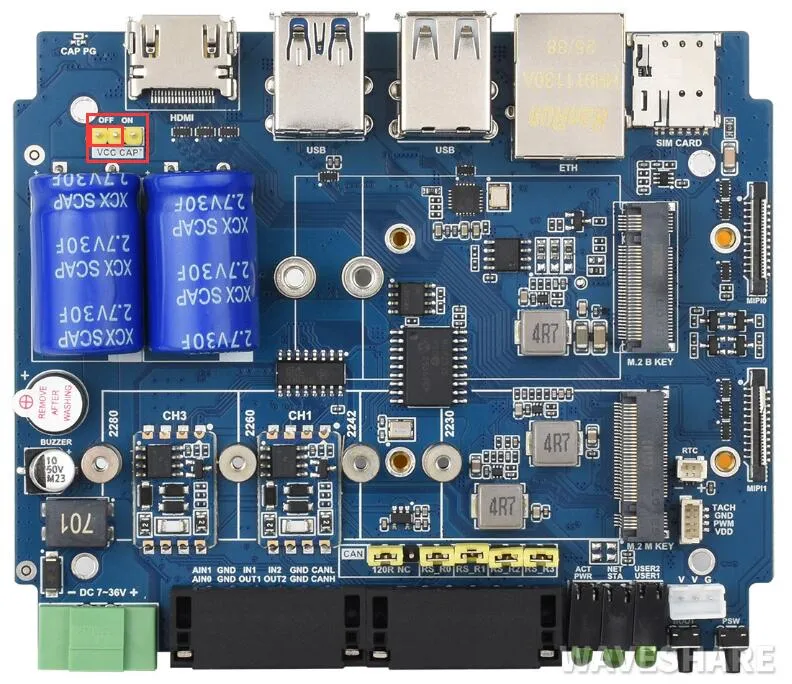
- After the capacitor power-loss protection function is enabled, the supercapacitor will provide additional power to the device for a period of time when the external power is lost, giving the user time to back up data.
- The product enables capacitor power-loss protection by default. To disable this function, move the jumper cap next to the large capacitor in the upper-left corner to OFF.
| Control Pin | Function | Description |
|---|---|---|
| GPIO11 | Capacitor Low-Voltage Warning | When the capacitor voltage is too low, the warning circuit pulls GPIO11 low |
| GPIO16 | External Power Cut Warning | When both the external Type-C and 7V-36V terminals are unpowered and the supercapacitor is providing backup power, the power-cut warning circuit pulls GPIO16 high |
Buzzer
| Control Pin | Function | Description |
|---|---|---|
| GPIO7 | Buzzer | Active buzzer |
- When the GPIO outputs high, the buzzer is silent.
- When the GPIO outputs low, the buzzer sounds.
LED Indicators
| LED Label | Function | Description |
|---|---|---|
| STAT | 4G/5G module enable LED | 4G/5G module interface LEDs |
| NET | 4G/5G module status LED | |
| PWR | Raspberry Pi system LEDs | Raspberry Pi system LEDs |
| ACT | Raspberry Pi activity LED | |
| USER1 | User‑definable LED 1 | Connected to GPIO25, active low |
| USER2 | User‑definable LED 2 | Connected to GPIO26, active low |