Working with ESP32S3
This chapter contains the following sections. Please read as needed:
Setting Up Development Environment
1. Installation and Configuration
- For setting up the ESP32S3 environment and basic usage, please refer to the following links:
- Once the environment is set up, you can connect the LoRa module and download the example programs
Hardware Connection
Connect according to the table below.
| Core2021-XF | ESP32S3 |
|---|---|
| CLK | 40 |
| MISO | 46 |
| MOSI | 45 |
| CS | 42 |
| DIO11 | 38 |
| RESET | 39 |
| BUSY | 41 |
Example
- ESP32S3 example programs are located in the
core2021-xf\examples\esp32s3directory of the example package. - Examples 01, 02, and 03 require two Core2021-XF modules: one for transmission and one for reception.
| Example | Basic Description | Dependency Library |
|---|---|---|
| 01_lr2021_tx | LR2021 Transmit | RadioLib |
| 02_lr2021_rx | LR2021 Receive | RadioLib |
| 03_lr2021_pingpong | LR2021 Ping-Pong | RadioLib |
| 04_lr2021_tx_cw | LR2021 CW Mode Transmit | RadioLib |
| 05_lr2021_LoRaWAN | LoRaWAN | RadioLib |
Run Arduino ESP32 Example
- Navigate to
core2021-xf\examples\esp32s3\arduinoand select the example program you wish to test. - Select the development board:
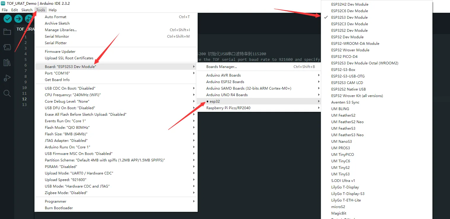
- Select the port for the ESP32S3, then compile and upload.
- After the upload is completed, open the serial port monitor, and the relevant information will be output.
01_lr2021_tx
Example Description
- Based on the ESP32S3 + Core2021-XF module, implements periodic LoRa packet transmission using interrupts.
- Custom SPI pins (CLK/MOSI/MISO) to match the ESP32S3 hardware design.
- Uses non-blocking transmission, does not occupy CPU resources in the main loop.
- After each packet is sent, automatically delays 1 second before sending the next packet.
- Supports string data transmission, with a built-in packet sequence number for easy debugging.
Code Analysis
SPI.begin(...): Initializes ESP32S3 hardware SPI pins with custom CLK/MOSI/MISO.radio.irqDioNum = 11: Configures the LR2021 interrupt mapping pin; must be set before initialization.radio.XTAL = true: Enables the external crystal oscillator to ensure frequency accuracy.setFlag(void): Interrupt callback function triggered automatically after the module finishes transmission, sets a transmission-complete flag.radio.setPacketSentAction(setFlag): Binds the transmission-complete interrupt function.radio.startTransmit("content"): Starts asynchronous LoRa transmission (supports string / byte array).radio.finishTransmit(): Cleanup after transmission, turns off the transmit circuit and resets the module state.loop()main logic: Check transmission-complete flag → print status → delay → send next packet with sequence number.
Operation Result
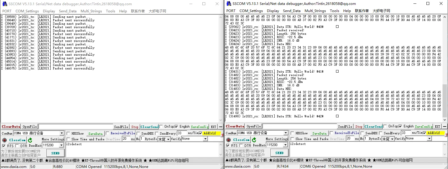
-
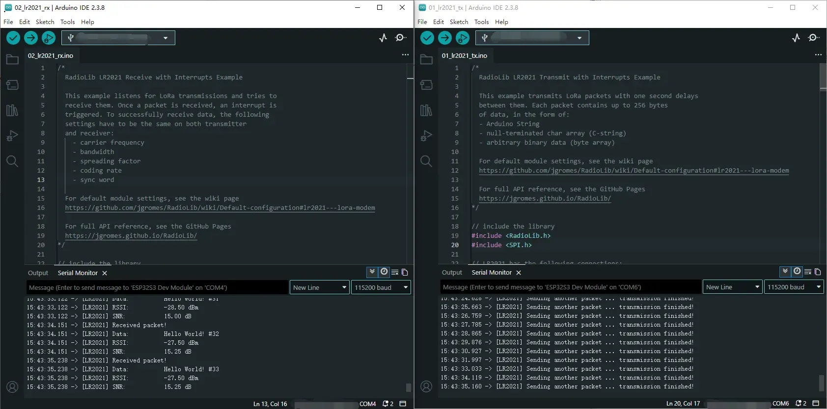
After compiling and uploading, open the serial monitor to see logs indicating transmission completion, as shown below (in combination with 02_lr2021_rx):
02_lr2021_rx
Example Description
- Based on the ESP32S3 + Core2021-XF module, implements wireless LoRa packet reception using interrupts.
- Custom hardware SPI pins to match the ESP32S3 hardware design.
- Uses non-blocking listening mode; the module automatically waits for data without consuming CPU resources.
- After successful reception, automatically parses the data and prints the packet content, RSSI, and SNR.
- The same frequency, spreading factor, bandwidth, and coding rate must be configured on both the transmitter and receiver for successful communication.
Code Analysis
SPI.begin(...): Initializes ESP32S3 hardware SPI with custom CLK/MOSI/MISO pins.radio.irqDioNum = 11: Configures the LR2021 interrupt mapping pin; must be set before initialization.radio.XTAL = true: Enables the external crystal oscillator to ensure frequency accuracy and improve reception stability.setFlag(void): Interrupt callback function triggered automatically after a complete packet is received.radio.setPacketReceivedAction(setFlag): Binds the reception-complete interrupt service function.radio.startReceive(): Starts continuous LoRa reception mode, enters a data-waiting state.radio.readData(str): Reads the received wireless data (supports string parsing).radio.getRSSI()/radio.getSNR(): Retrieves signal quality parameters for debugging and link evaluation.loop()main logic: Check reception-complete flag → read data → parse and print → continue listening.
Operation Result
-
After compiling and uploading, open the serial monitor to see real-time reception logs including data content, RSSI, and SNR, as shown below (in combination with 01_lr2021_tx):
03_lr2021_pingpong
Example Description
- Based on the ESP32S3 + Core2021-XF module, implements LoRa automatic ping-pong (question-answer) two-way communication.
- Custom hardware SPI pins to match the ESP32S3 hardware design.
- Two modules can send and receive to each other without manual control.
- Enabling
INITIATING_NODEsets the module as the initiator; the other module acts as the responder. - Automatically switches between transmit and receive states, driven by non-blocking interrupts.
Code Analysis
SPI.begin(...): Initializes ESP32S3 hardware SPI with custom CLK/MOSI/MISO pins.radio.irqDioNum = 11: Configures the LR2021 interrupt mapping pin; must be set before initialization.radio.XTAL = true: Enables the external crystal oscillator to ensure communication frequency accuracy.setFlag(void): General interrupt callback, triggered on either transmit or receive completion.radio.setIrqAction(setFlag): Binds the shared transmit/receive interrupt function.INITIATING_NODEmacro: Used to distinguish the initiating node.radio.startTransmit(): Starts packet transmission.radio.startReceive(): Switches the module to listening (receive) mode.radio.readData(str): Reads the received LoRa packet.loop()main logic: Transmit complete → enter receive; receive complete → delay reply → transmit again.
Operation Result
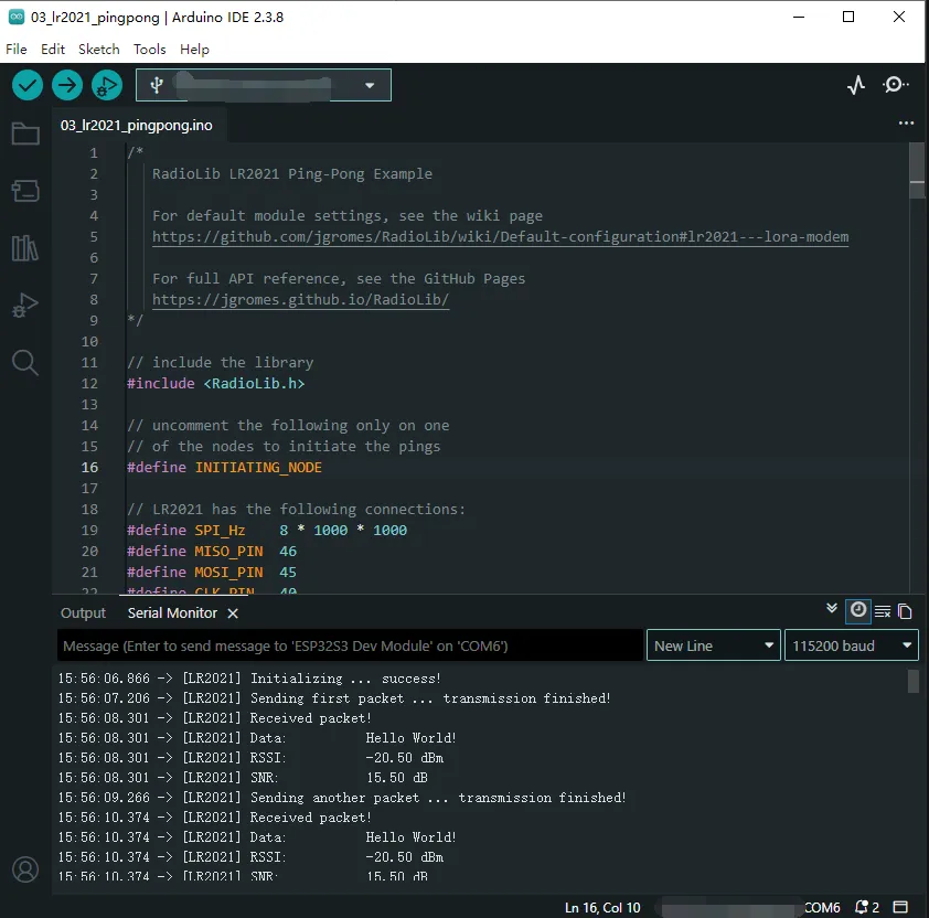
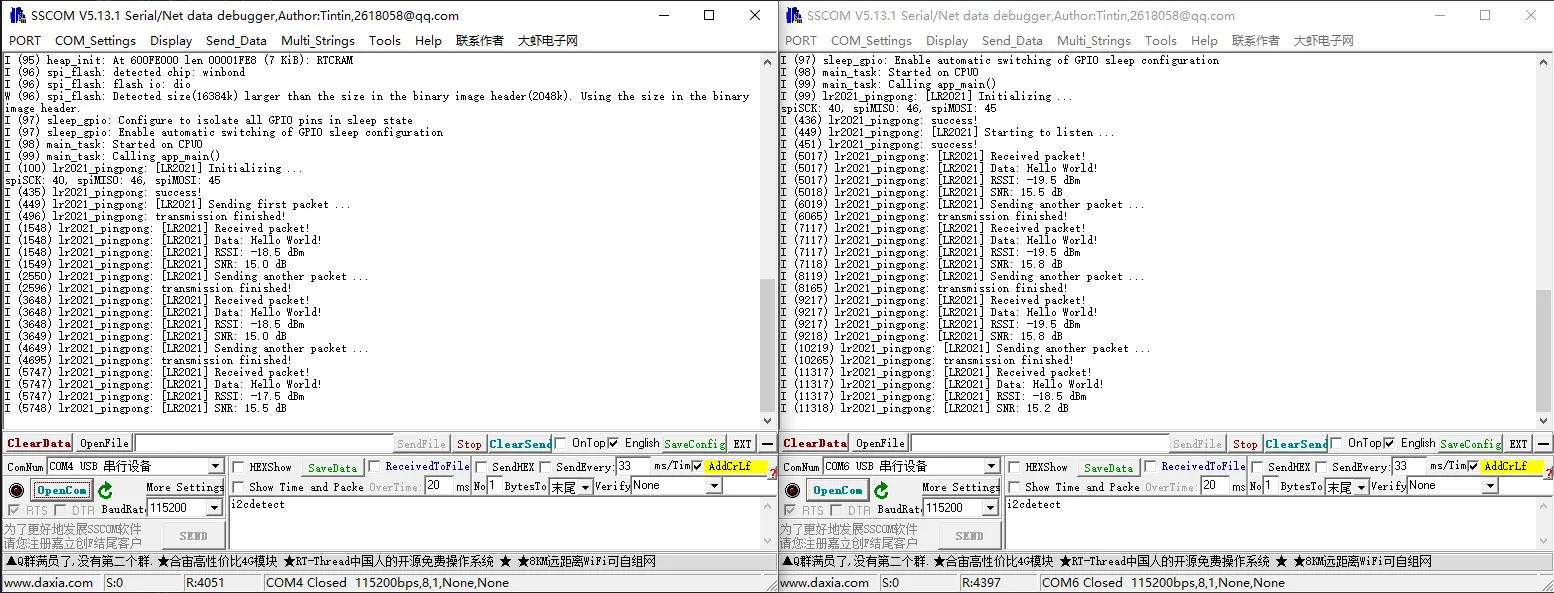
- Flash the program onto two modules, enabling the
INITIATING_NODEmacro on one of them. - After power-on, they automatically send and receive to each other; the serial monitor prints the transmit/receive status, data, RSSI, and SNR, as shown below:
04_lr2021_tx_cw
Example Description
- Based on the ESP32S3 + Core2021-XF module, implements LoRa continuous wave (CW) / direct transmit.
- Custom SPI pins to match the ESP32S3 hardware design.
- Outputs a fixed-frequency carrier signal without packet formatting, used for band testing, signal detection, and instrument calibration.
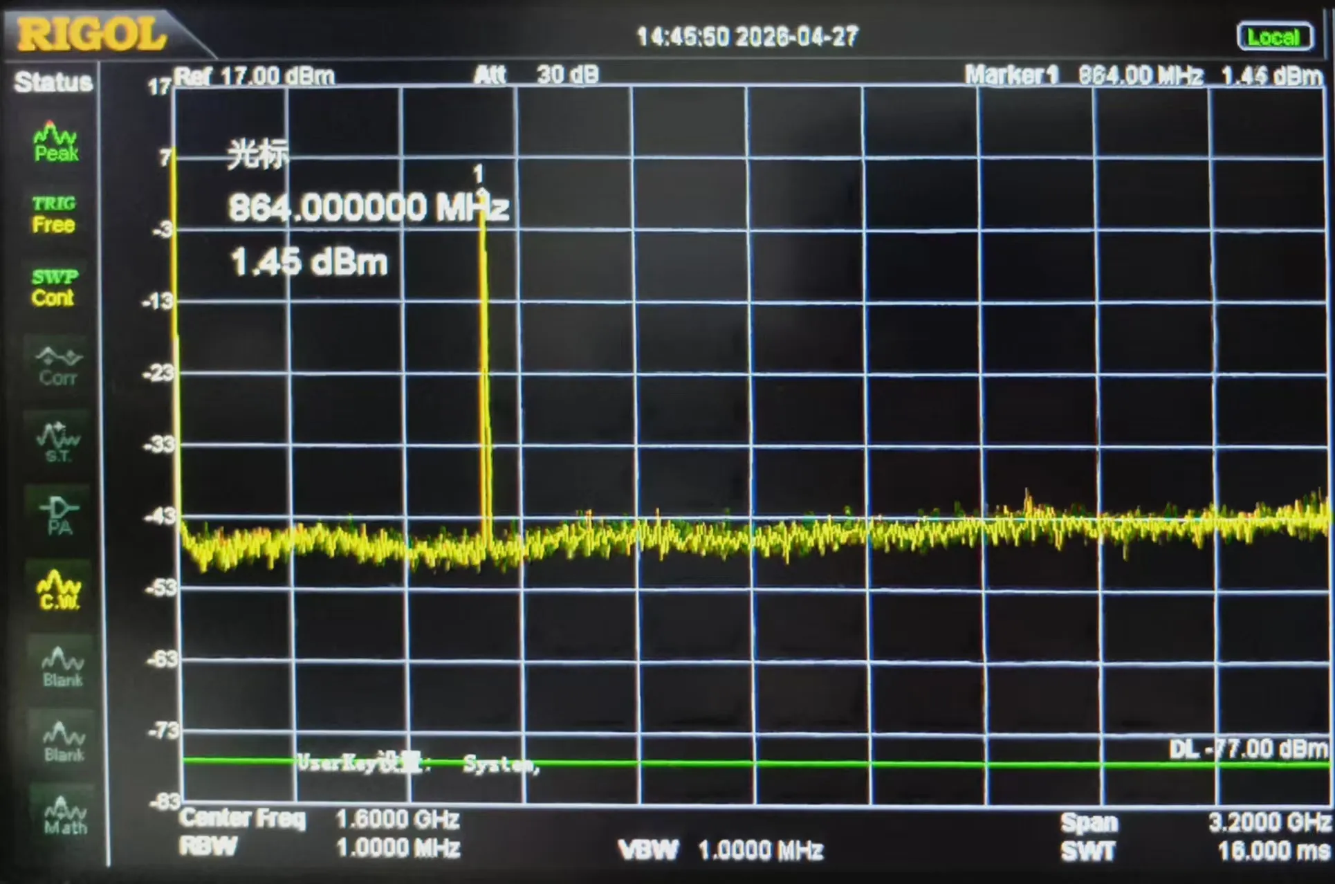
- Fixed frequency 868 MHz, transmit power 22 dBm.
- Upon power-up, transmits continuously with no additional logic.
Code Analysis
SPI.begin(...): Initializes ESP32S3 hardware SPI with custom CLK/MOSI/MISO pins.radio.XTAL = true: Enables the external crystal oscillator to ensure carrier frequency accuracy.OUT_HZ 868000000UL: Defines the direct transmit frequency (868 MHz); can be modified.radio.setOutputPower(22): Sets the transmit power to 22 dBm.radio.transmitDirect(OUT_HZ): Enters continuous direct transmission mode, outputting a fixed-frequency carrier.loop(): No business logic; the carrier continues to transmit without program intervention.
Operation Result
-
After flashing, the module immediately outputs a fixed-frequency carrier signal.
-
The serial port prints initialization and transmission start status; a spectrum analyzer or receiving module can detect the continuous RF signal, as shown below:
05_lr2021_LoRaWAN
Example Description
- Based on the ESP32S3 + Core2021-XF module, implements LoRaWAN OTAA join + uplink/downlink communication.
- Custom SPI pins to match the ESP32S3 hardware design.
- Uses NVS flash to store session information, allowing fast reconnection after power-off reboot without re-joining.
- Periodically uploads random data (default every 5 minutes) and automatically listens for server downlink messages.
- Supports printing downlink data in HEX/ASCII formats for easy debugging and link verification.
Code Analysis
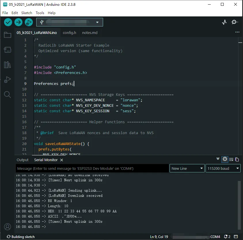
SPI.begin(...): Initializes ESP32S3 hardware SPI with custom CLK/MOSI/MISO pins.radio.irqDioNum = 11: Configures the LR2021 interrupt mapping; must be set before initialization.radio.XTAL = true: Enables the external crystal oscillator to ensure LoRaWAN frequency accuracy.prefs.begin(...): Initializes the ESP32 NVS partition for storing LoRaWAN session information.restoreLoRaWANState(): Restores session information from NVS for fast reconnection.node.beginOTAA()/node.activateOTAA(): OTAA join functions.saveLoRaWANState(): Saves session information to NVS after successful join.node.sendReceive(): Sends uplink data and automatically listens for server downlink messages.printHex / printAscii: Formats and prints received data.
Operation Result
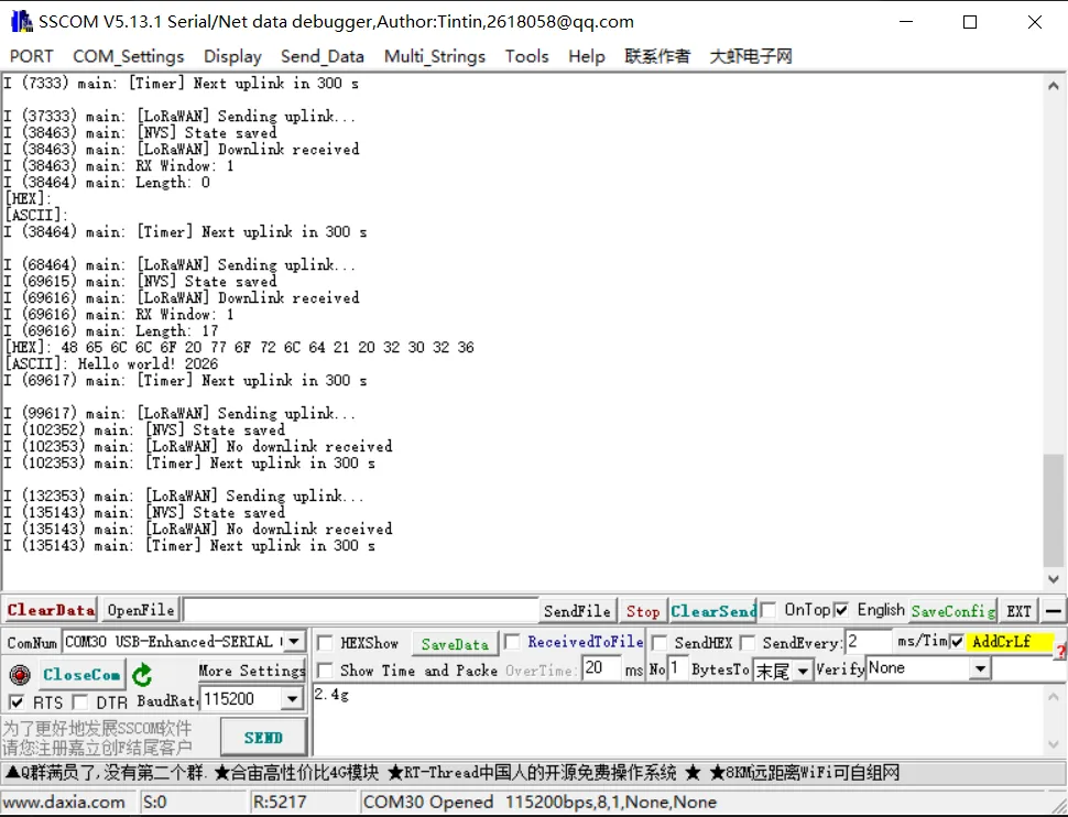
-
After flashing, the module automatically completes OTAA join, periodically reports data, and listens for downlink messages.
-
The serial port prints join status, uplink/downlink messages, signal quality, etc., as shown below:
Run ESP-IDF Example
01_lr2021_tx
Example Description
- Based on the native ESP-IDF framework + ESP32S3 + Core2021-XF module, implements periodic LoRa packet transmission using interrupts.
- Includes a dedicated hardware abstraction layer
EspHal.hthat perfectly adapts to the ESP-IDF environment. - Custom SPI pin configuration supporting hardware SPI2 bus.
- Uses interrupt-driven non-blocking transmission, automatically sending one packet with sequence number every second.
- Log output uses the native ESP-IDF
ESP_LOGfor stable and reliable operation.
Core Files
EspHal.h: ESP-IDF hardware abstraction layer providing low-level implementations for GPIO, SPI, delays, and interrupts (common to all examples).main.cpp: LoRa transmit main program.
Code Analysis
EspHal* hal = new EspHal(...): Initializes the ESP-IDF hardware abstraction layer.radio.irqDioNum = 11: Configures the LR2021 interrupt mapping pin.radio.XTAL = true: Enables the external crystal oscillator to ensure frequency accuracy.setFlag(void): Transmit-complete interrupt callback function.radio.setPacketSentAction(setFlag): Binds the transmit-complete interrupt.radio.startTransmit(...): Starts asynchronous LoRa transmission.radio.finishTransmit(): Turns off the RF circuit after transmission to ensure low-power stability.
Operation Result
- After compiling and flashing, the serial port prints the transmission status and packet sequence number in real time.
- Can be paired with 02_lr2021_rx to complete one-way LoRa wireless communication in the ESP-IDF environment.
02_lr2021_rx
Example Description
- Based on the native ESP-IDF framework + ESP32S3 + Core2021-XF module, implements wireless LoRa packet reception using interrupts.
- Relies on the generic hardware abstraction layer
EspHal.hfor perfect adaptation to the ESP-IDF environment. - Custom SPI pin configuration supporting hardware SPI2 bus.
- Interrupt-driven non-blocking listening, receiving data in real time.
- After reception, automatically prints: length, RSSI, SNR, HEX format, and string format.
Core Files
EspHal.h: Low-level hardware abstraction (common to all examples).main.cpp: LoRa receive main program.
Code Analysis
EspHal* hal: Initializes ESP-IDF hardware abstraction (GPIO/SPI/interrupts).radio.irqDioNum = 11: Configures the LR2021 interrupt mapping.radio.XTAL = true: Enables the external crystal oscillator to ensure receive frequency accuracy.setFlag(void): Receive-complete interrupt callback.radio.setPacketReceivedAction(setFlag): Binds the receive-complete interrupt.radio.startReceive(): Starts continuous LoRa listening.radio.readData(): Reads and parses the received packet.- Automatically restarts listening, enabling continuous reception.
Operation Result
- After flashing, the module enters listening mode and prints data as soon as it is received.
- Can be paired with 01_lr2021_tx to complete full wireless communication.
03_lr2021_pingpong
Example Description
- Based on the native ESP-IDF framework + ESP32S3 + Core2021-XF module, implements automatic LoRa ping-pong bidirectional communication (question-answer).
- Relies on the generic hardware abstraction layer
EspHal.hfor perfect adaptation to the ESP-IDF environment. - Custom SPI pin configuration supporting hardware SPI2 bus.
- Uses interrupt-driven non-blocking mechanisms, automatically switching between transmit and receive states.
- Supports distinguishing the initiating node from the listening node via a macro; upon power-up they automatically send and receive to each other.
- Upon receiving a packet, automatically prints the payload content, RSSI, and SNR for easy link debugging.
Core Files
EspHal.h: Low-level hardware abstraction (common to all ESP-IDF examples).main.cpp: LoRa ping-pong bidirectional communication application.
Code Analysis
EspHal* hal: Instantiates the ESP-IDF hardware abstraction layer (SPI, GPIO, delays, interrupts).radio.irqDioNum = 11: Configures the LR2021 interrupt mapping pin.radio.XTAL = true: Enables the external crystal oscillator to ensure LoRa frequency accuracy.setFlag(void): Common interrupt callback for both transmit and receive events.radio.setIrqAction(setFlag): Binds the module interrupt callback.INITIATING_NODE: Macro switch that defines the device as the active packet-sending node.radio.startTransmit()/radio.startReceive(): The program automatically switches between transmit and listen modes.radio.readData(): Parses received packets and prints text and signal parameters.- Closed-loop logic: after sending, switch to receive; after receiving, delay and automatically reply, continuing the ping-pong cycle.
Operation Result
- After flashing both ESP32s, they automatically establish a bidirectional LoRa link and exchange data continuously.
- The serial terminal prints initialization status, transmission/reception results, RSSI, and SNR in real time.
04_lr2021_tx_cw
Example Description
- Based on the native ESP-IDF framework + ESP32S3 + Core2021-XF module, implements fixed-frequency continuous wave (CW) transmission.
- Relies on the generic hardware abstraction layer
EspHal.hfor perfect adaptation to the ESP-IDF environment. - Custom SPI pin configuration supporting hardware SPI2 bus.
- Outputs a clean, packet-free continuous RF signal, suitable for instrument calibration, band testing, and signal strength detection.
- Transmission frequency: 868 MHz, transmit power: 22 dBm; continuously transmits after power-up without interruption.
Core Files
EspHal.h: Low-level hardware abstraction (common to all ESP-IDF examples).04_lr2021_direct_transmit.c: LoRa carrier transmission main program.
Code Analysis
EspHal* hal: Initializes ESP-IDF hardware abstraction (SPI, GPIO, delays, interrupts).radio.irqDioNum = 11: Configures the LR2021 interrupt mapping pin.radio.XTAL = true: Enables the external crystal oscillator to ensure carrier frequency accuracy.OUT_HZ 868000000UL: Defines the continuous transmit frequency (868 MHz).radio.setOutputPower(22): Sets the transmit power to 22 dBm.radio.transmitDirect(OUT_HZ): Enters direct carrier transmission mode, starting continuous transmission.
Operation Result
- After flashing, the module immediately outputs a stable continuous RF signal.
- A spectrum analyzer or receiving device can detect the stable carrier for band testing and calibration.
05_lr2021_LoRaWAN
Example Description
- Based on the native ESP-IDF framework + ESP32S3 + Core2021-XF module, implements LoRaWAN OTAA join + periodic uplink + downlink reception.
- Relies on the generic hardware abstraction layer
EspHal.h; runs independently in the pure ESP-IDF environment. - Uses NVS flash to persistently store session information, allowing fast recovery after power-off without re-joining.
- Automatically reports random test data, supports parsing and printing of server downlink data.
- Full log output: join status, signal quality, uplink/downlink data, session save records.
Core Files
EspHal.h: Low-level hardware abstraction (common to all ESP-IDF examples).05_lr2021_lorawan_otaa.c: LoRaWAN OTAA communication main program.
Code Analysis
EspHal* hal: Initializes ESP-IDF hardware abstraction (SPI, GPIO, delays, interrupts).radio.irqDioNum = 11: Configures the LR2021 interrupt mapping pin.radio.XTAL = true: Enables the external crystal oscillator to ensure LoRa frequency accuracy.nvs_flash_init(): Enables NVS storage for saving LoRaWAN session information.restoreLoRaWANState(): Recovers session from flash for fast reconnection.node.beginOTAA()/node.activateOTAA(): OTAA join key functions.node.sendReceive(): Sends uplink data and listens for server downlink messages.printHex / printAscii: Formats and prints downlink data.
Operation Result
- After the program runs, it automatically completes OTAA join, periodically reports data, and receives downlink messages from the server.
- The serial terminal prints join status, upload records, signal quality, and downlink content in real time.