LoRaWAN Environment Setup
LoRa and LoRaWAN
What is LoRa?
Semtech's LoRa is a long-range, low-power wireless platform for the Internet of Things (IoT). Generally, it refers to radio frequency chips using LoRa technology. Its main features are as follows:
-
LoRa (short for long range) uses a spread spectrum modulation technology derived from Chirp Spread Spectrum (CSS) technology. It is a type of long-distance wireless transmission technology and LPWAN communication technology. Spread spectrum technology trades bandwidth for sensitivity. Technologies like Wi-Fi and ZigBee also use spread spectrum, but LoRa modulation is characterized by approaching the Shannon-Hartley theorem limit, maximizing sensitivity improvement. Compared to traditional FSK technology, at the same communication rate, LoRa has 8~12 dBm better sensitivity than FSK. Currently, LoRa primarily operates in the Sub-GHz ISM bands.
-
LoRa technology integrates digital spread spectrum, digital signal processing, and forward error correction coding, significantly improving long-distance communication performance. LoRa's link budget is superior to any other standardized communication technology; the link budget is the main factor determining distance in a given environment.
-
LoRa RF chips mainly include the SX127X series, SX126X series, and SX130X series. The SX127X and SX126X series are used for LoRa nodes, while the SX130X series is used for LoRa gateways. For details, refer to Semtech's product list.
What is LoRaWAN?
-
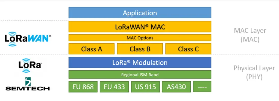
LoRaWAN is an open protocol for Low-Power Wide-Area Networks (LPWAN) built on top of the LoRa radio modulation technique. It is designed to wirelessly connect battery-powered "things" to the internet in regional, national, or global networks, targeting key IoT requirements such as bidirectional end-to-end communication, end-to-end security, mobility, and localization services. Nodes require network join authentication to connect wirelessly to the internet, establishing an encrypted communication channel between the node and the server. The LoRaWAN protocol layers are shown in the figure below.
-
The Class A/B/C node device types in the MAC layer cover almost all IoT application scenarios. The difference between them lies in the transmission and reception time slots of the nodes.
-
In the Modulation layer, parameters like EU868 and AS430 indicate different frequency bands used in different countries. Please refer to the link for regional parameters.
-
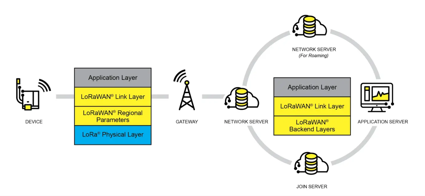
Implementing a LoRaWAN network covering a city or other area requires four components: nodes (LoRa node RF chips), gateways (or base stations, LoRa gateway RF chips), servers, and the cloud, as shown in the figure below.
-
A DEVICE (node device) must first initiate a join request packet to the GATEWAY and then to the server. Only after successful authentication can it normally send and receive application data with the server.
-
The GATEWAY can communicate with the server via wired networks or 3/4/5G wireless networks.
-
Major server-side operators include TTN, etc. For setting up your own cloud service, please refer to lorawan-stack or chirpstack.
Application
- This application is based on the official LoRaWAN example
ModemE_application_examplesand only demonstrates the basic LoRaWAN Class A application. Other advanced examples can be ported from the official repository, including: Join Request, LoRaWAN Class B application, LoRaWAN Multicast Class B/C examples, and FUOTA examples.
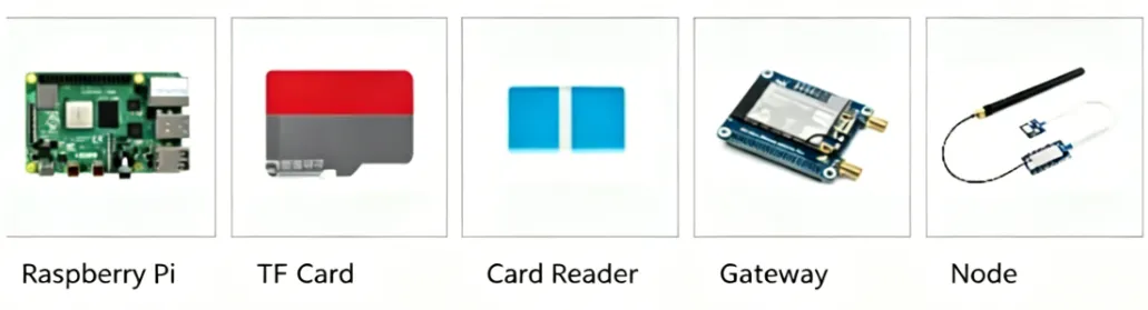
Required Components
-
Raspberry Pi 4B (with compatible power supply)
-
TF card (TF card with a capacity greater than 8GB is recommended)
-
Card reader
-
Gateway device
-
Node device
-
Development board (optional models): ESP32, Raspberry Pi, STM32, and Raspberry Pi Pico
Server Setup
-
This example uses ChirpStack as the LoRaWAN network server. Please follow the official Raspberry Pi installation steps for configuration.
-
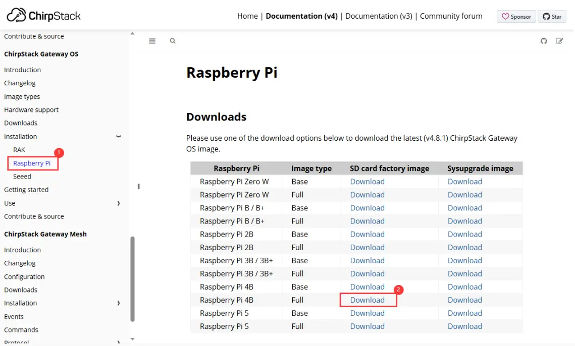
First, download the ChirpStack Gateway OS image, extract it, and use Win32DiskImager to write the image to the TF card.
Downloading the Image
Writing the Image

-
After writing, please refer to the official documentation for detailed configuration. This document only provides a brief installation guide. For details, see: ChirpStack Gateway OS Getting Started Guide.
-
Insert the TF card into the Raspberry Pi and power it on. After booting, your computer's Wi-Fi should detect a wireless hotspot named
ChirpStackAP-XXXXXXwith the passwordChirpStackAP. After connecting successfully, access192.168.0.1in a browser to open the ChirpStack management interface. No password is required for the first login.Connecting to Wi-Fi

Accessing the Web Interface

-
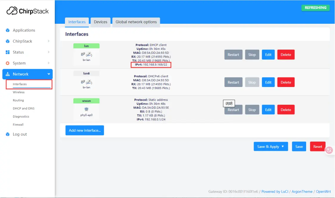
After booting, you can connect to an external network via Ethernet or Wi-Fi. Here, connecting via Ethernet is used as an example. To configure Wi-Fi, please refer to: Wi-Fi Configuration. After connecting to the network, you can view the current IP address in the web management interface.
Adding a Gateway
-
After the server configuration is complete and the IP address is obtained, power off the Raspberry Pi and disconnect the power. Connect the SX1303-868M-LoRaWAN-Gateway-HAT (gateway device) to the Raspberry Pi and attach the antenna. Power on the Raspberry Pi. In your browser, navigate to the previously obtained IP address to enter the ChirpStack management interface. Click ChirpStack -> Concentratord and enable the gateway function. Using the SX1303 (868 MHz) as an example, configure it as shown below, then click "Save & Apply":
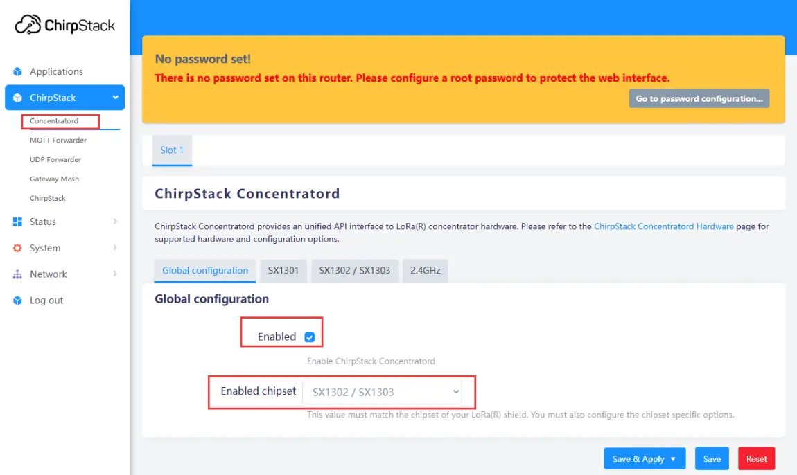
Enabling the Gateway
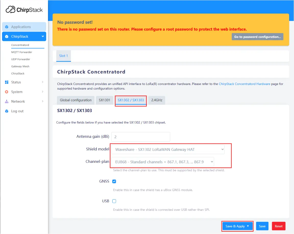
Configuring Gateway Parameters
-
Use the IP address obtained earlier to access the device remotely via an SSH tool (e.g., MobaXterm). The default username is
root. After a successful connection, enter the following command in the terminal to get the gateway ID:gateway-id. The system will output the current device's gateway ID. Make a note of this ID; it will be needed when adding the gateway later.
-
Navigate to Applications -> ChirpStack. The first time you enter, you need to log in. The default username and password are both
admin. After logging in, click Gateways -> Add gateway, fill in the gateway-id obtained earlier on the Add page, and save it. Return to the Gateway page to see if the gateway has been successfully launched.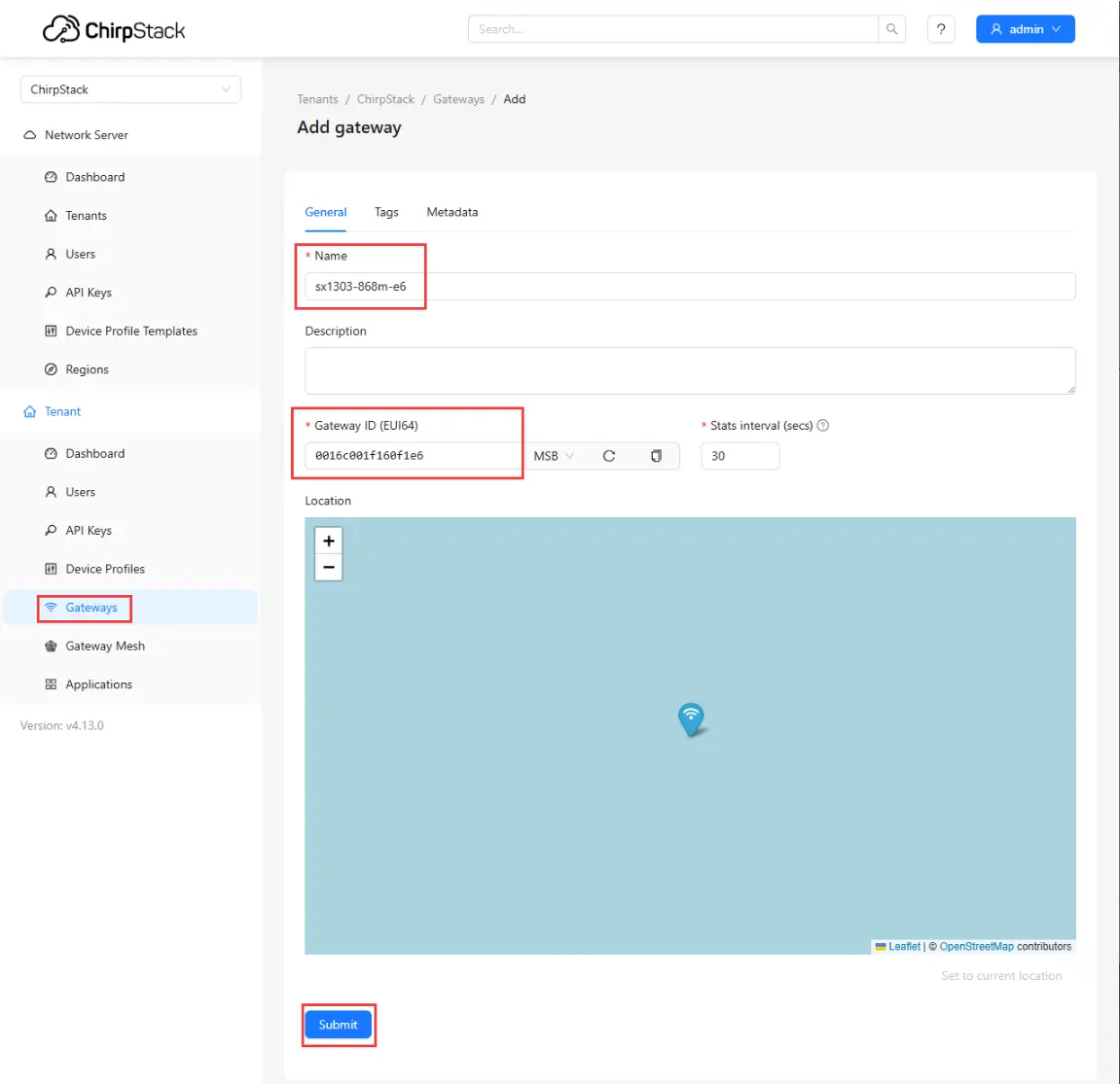
Adding Gateway to Server
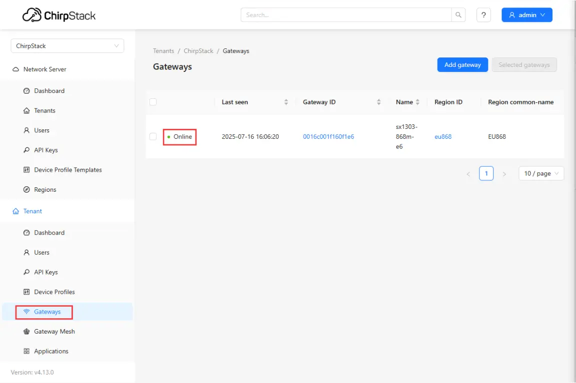
Checking if Gateway is Online
Adding a Node
-
This example uses the Core1121-XF as the node.
-
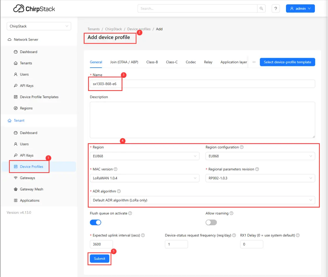
First, add a device profile in the web interface: Device Profiles -> Add device profile. Configure as shown in the figure below:
-
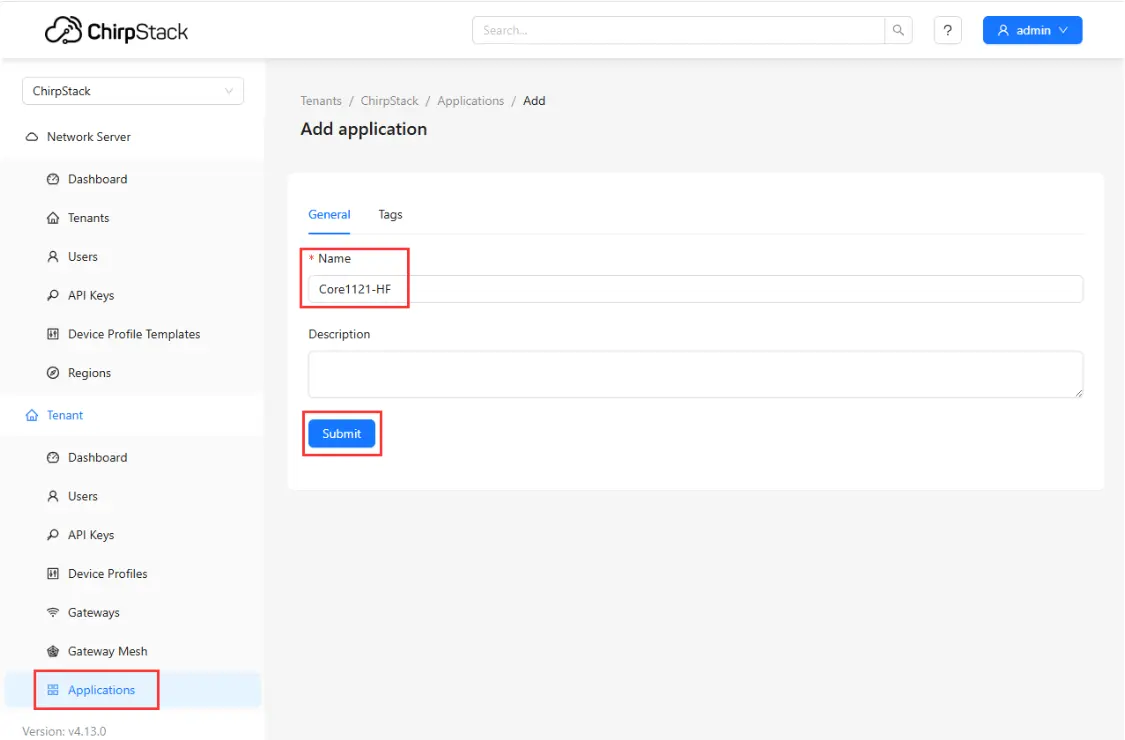
Then, add an application: Applications -> Add application, fill in the relevant information, and save:
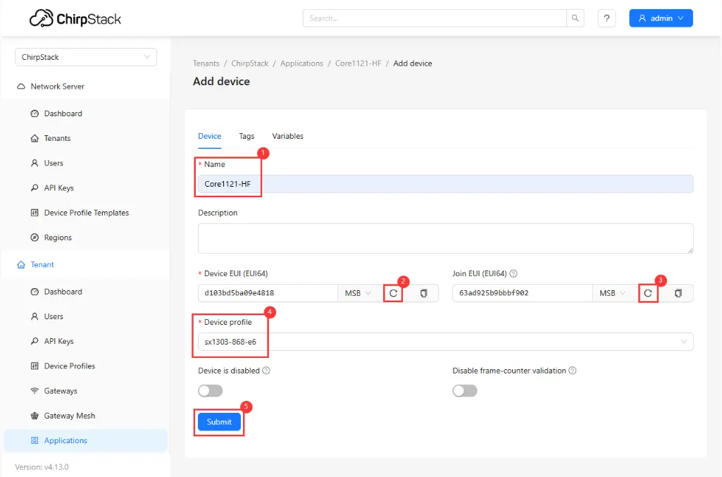
Setting EUI
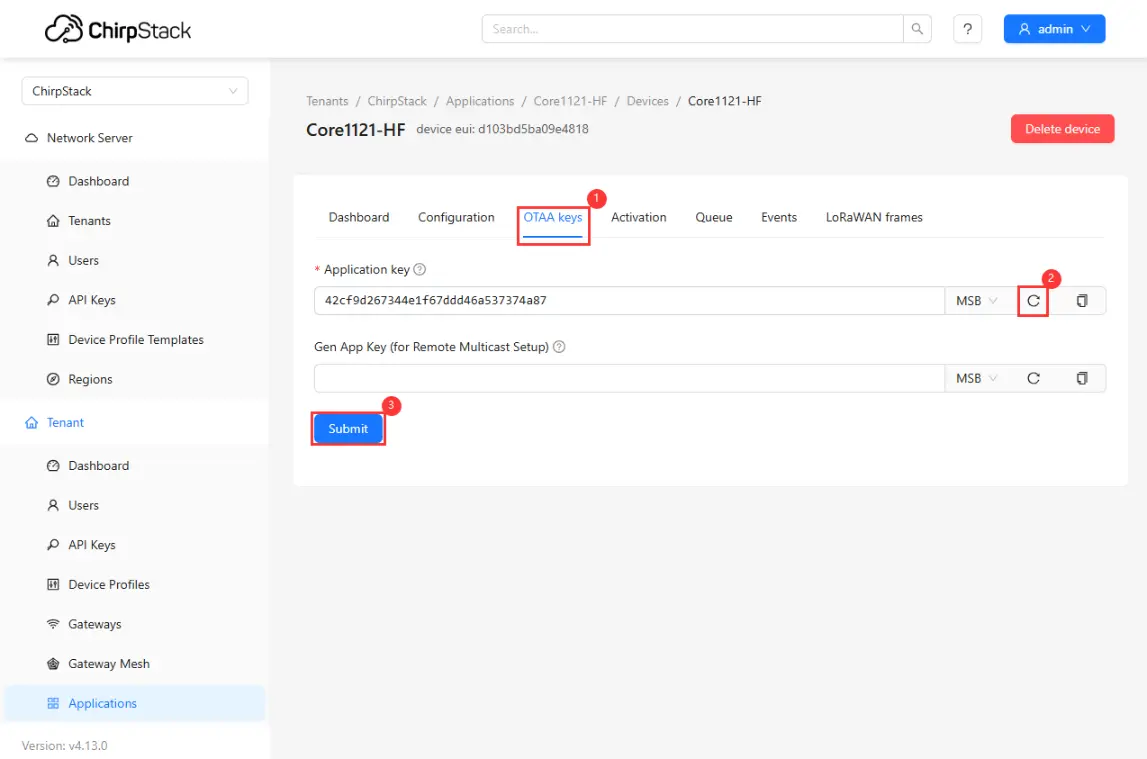
Setting Key
-
Use the
05_lr2021_LoRaWANexample program. Open it and go to the directory:core2021-xf\examples\arduino\05_lr2021_LoRaWAN. Edit theconfig.hfile and fill in the EUI and keys generated earlier in the corresponding fields. Then compile and flash.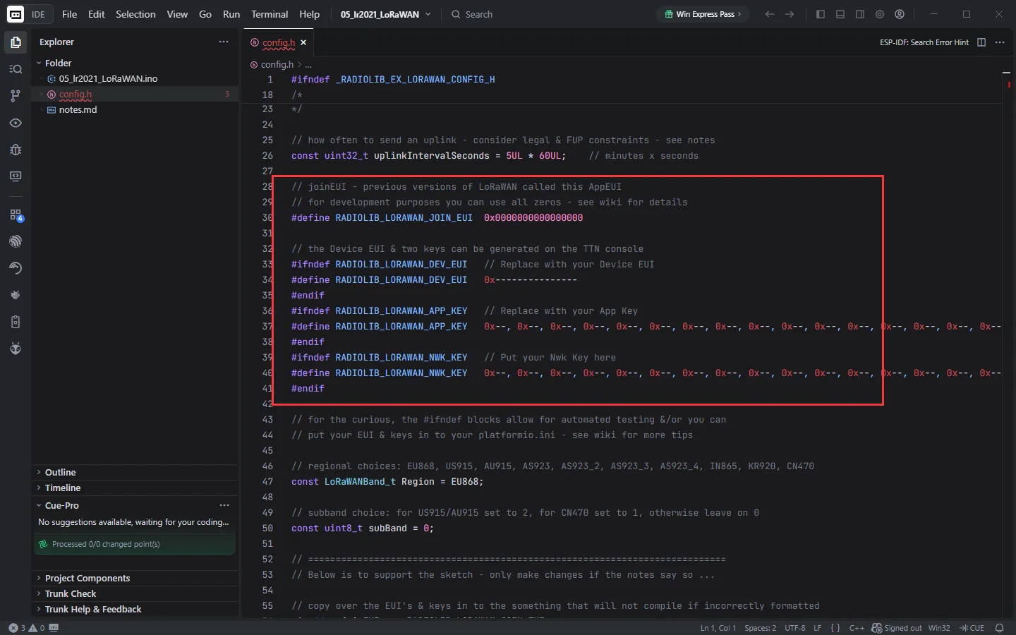
-
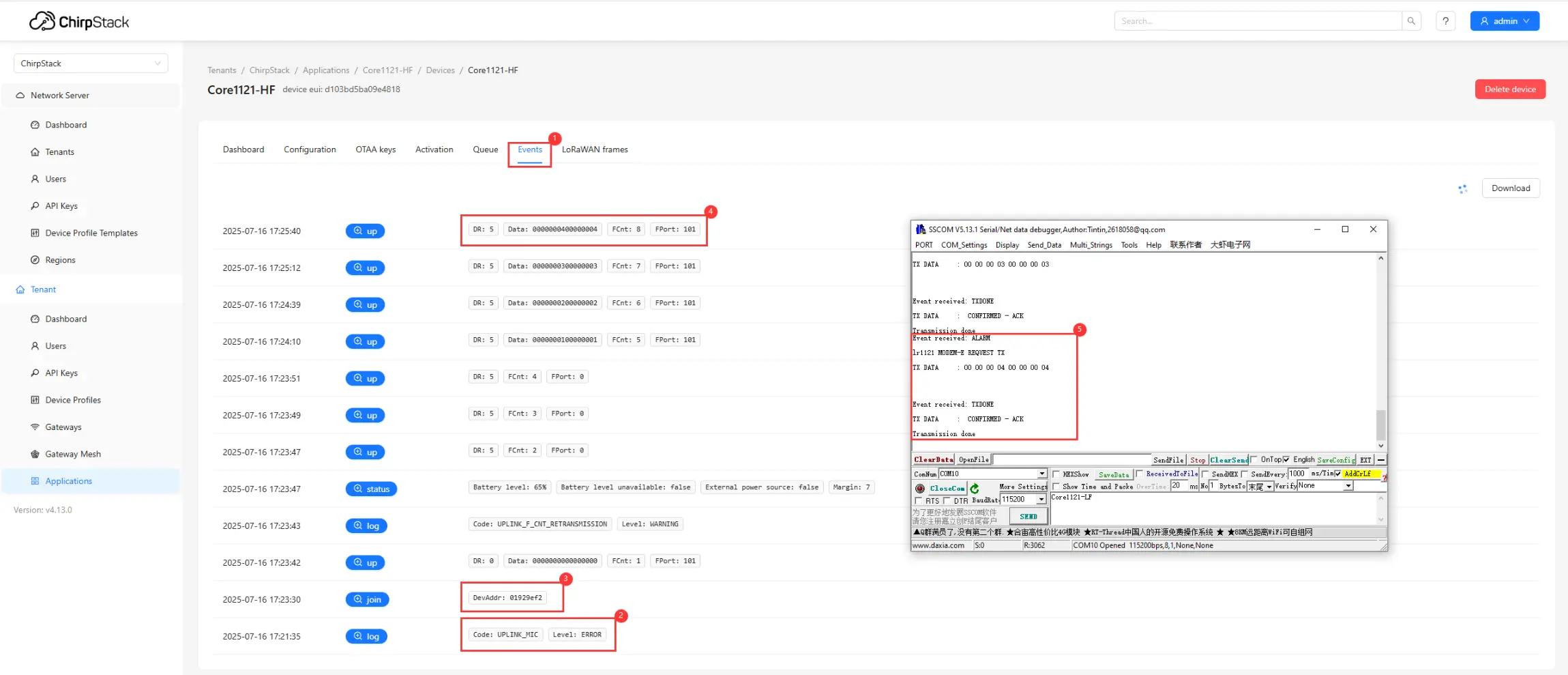
After flashing, the node will automatically request to join the LoRaWAN network. Upon successful joining, the node will periodically send uplink data. You can view device events and communication status through the web interface:
①. Click Events to view the node's operating status.
②. Check for join failures.
③. If joining is successful, you can see the join event.
④. View the data reported by the node.
⑤. View debug information via the serial port.
-
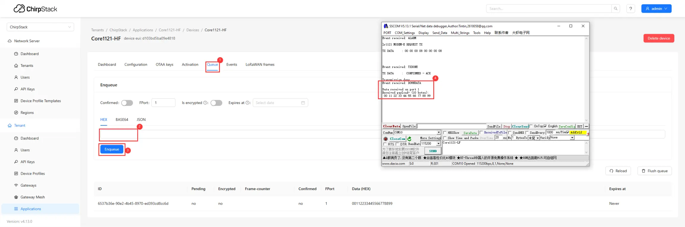
The server also supports sending downlink data to the node:
①. Click Queue.
②. Enter the hexadecimal data to be sent.
③. Click Send.
④. The node receives the data and prints it on the serial port.