DDSM350-CT
This product is an integrated servo hub motor with a compact 4.5inch outer-diameter design. It highly integrates an outer-rotor brushless motor, high-precision encoder and servo drive, featuring simple installation. It is suitable for direct-drive applications such as robot joints, compact AGVs and service robots. The motor delivers a rated torque of 1.1 N·m, peak torque of 3 N·m and a maximum speed of 350 rpm. It provides precise, low-noise motion control, supports dual-communication via UART and CAN, and incorporates multiple protections including over-voltage and over-temperature and short-circuit protection. It reaches an IP67 ingress-protection rating (excluding the shaft end), delivering a reliable and efficient direct-drive solution for mobile robots.
| SKU | Product |
|---|---|
| 35594 | DDSM350-CT |
Specifications
- Rated Speed: 270 rpm
- Rated Torque: 1.1 N·m
- Peak Torque: 3 N·m
- No-Load Speed: 350 rpm
- Total Weight: 1286±10 g
- Torque Constant: 0.5 N·m/rpm
- Operating Ambient Temperature: -10 - 40 °C
- Encoder Resolution: 12-bit
- Peak Current: 5.8 A
- Rated Current: 2.2 A
- Noise Level: ≤60 dB
- Rated Voltage: 24 V DC
- Ingress-Protection Rating: IP67
Features
- Ultra-low noise
- High-precision, zero-backlash output
- Fast response, zero-latency direct drive
- All-in-one motor-and-driver design for compact structure and high integration
- Supports CAN and TTL-232 communication interfaces
- Real-time access to motor position, velocity, current, fault codes and other operating data over communications
- Built-in over-current, overload and over-temperature protection
- High-level ingress protection, dust-resistant and capable of withstanding axial impact loads
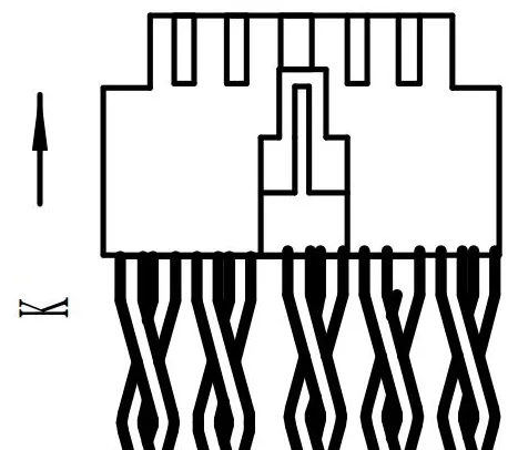
Interface & Pinout Description
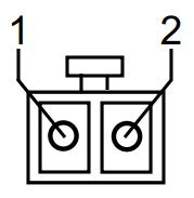

Connector Model: VH3.96
| Pin No. | Wire Color | Definition |
|---|---|---|
| 1 | Red | Power Positive |
| 2 | Black | Power Negative |
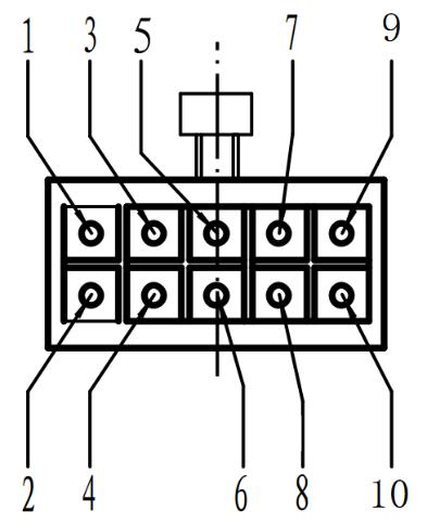
Connector Model: PHB2.0
| Pin No. | Wire Color | Pin Name | Pin Function | Remarks |
|---|---|---|---|---|
| 1 | Red | DOUT1 | Default Alarm Output | Open-collector output, max. sink current: 100 mA; external pull-up voltage range: 5-24 V |
| 2 | White | DIN1 | Default Emergency-Stop Input | Active-low or dry-contact signal |
| 3 | Yellow | CAN_H / 485_A | CAN interface for CAN-version drives; RS485-A for RS485-version drives | Default CAN baud rate: 500 Kbps; Default RS485 baud rate: 38400 bps |
| 4 | Orange | CAN_L / 485_B | CAN interface for CAN-version drives; RS485-B for RS485-version drives | Default CAN baud rate: 500 Kbps; Default RS485 baud rate: 38400 bps |
| 5 | Green | GND | Common ground for communication and I/O signals | |
| 6 | Black | GND | Common ground for communication and I/O signals | |
| 7 | Gray | UART_RX | UART Receive Pin | TTL-level UART, 232 protocol, fixed baud rate: 115200 bps |
| 8 | Purple | UART_TX | UART Transmit Pin | TTL-level UART, 232 protocol, fixed baud rate: 115200 bps |
| 9 | Brown | ID1 | Slave-Station Address Selection | ID1 floating + ID2 floating: use saved onboard address (default = 1); ID1 tied-to-GND + ID2 floating: Station ID = 1; ID1 floating + ID2 tied-to-GND: Station ID = 2; ID1 tied-to-GND + ID2 tied-to-GND: Station ID = 3. The drive samples the ID state at power-on. Any online ID change requires a power cycle to take effect |
| 10 | Blue | ID2 | Slave-Station Address Selection | ID1 floating + ID2 floating: use saved onboard address (default = 1); ID1 tied-to-GND + ID2 floating: Station ID = 1; ID1 floating + ID2 tied-to-GND: Station ID = 2; ID1 tied-to-GND + ID2 tied-to-GND: Station ID = 3. The drive samples the ID state at power-on. Any online ID change requires a power cycle to take effect |
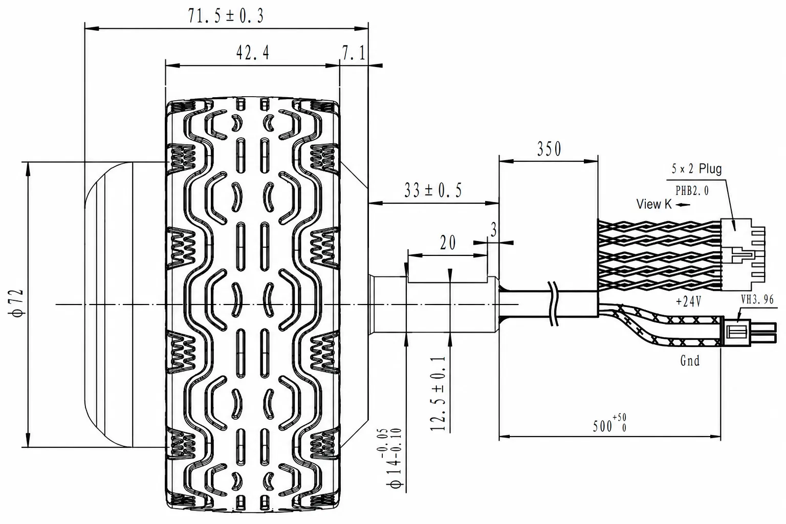
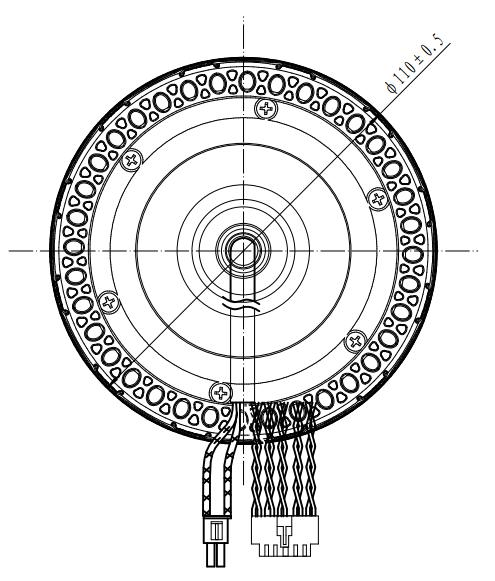
Dimensions