CAN Communication Function
The CAN interface on this device supports the CANopen SDO data transfer protocol. SDO is mainly used to transmit low-priority objects between devices. This data transfer is similar to MODBUS, i.e. after the master station sends a request, the slave station shall return a data response: Client→Server / Server→Client. This is the basic structure of an SDO. The CAN bus uses termination resistors. A 120Ω termination resistor must be placed between CAN_H and CAN_L at each of the two end nodes of the bus to suppress signal reflections and improve communication stability. Intermediate nodes on the bus should not have termination resistors, as doing so would lower the equivalent bus impedance and compromise communication reliability.
| Basic SDO Structure | |||
|---|---|---|---|
| Byte0 | Byte1-2 | Byte3 | Byte4-7 |
| SDO Command Specifier | Object Index | Object SubIndex | Up to 4-byte Data |
The 2-byte Object Index and the up-to-4-byte data are transmitted in little-endian (low-order byte first, high-order byte last).
For example, for an object index of 0x606C, Byte1 = 0x6C, Byte2 = 0x60.
Read Parameters
| Identifier | DLC | Data | ||||||||
|---|---|---|---|---|---|---|---|---|---|---|
| 0 | 1 | 2 | 3 | 4 | 5 | 6 | 7 | |||
| Transmit SDO Message | 0x600+Node_ID | 8 | Transmit Command Code | Object Index | Object SubIndex | 00 | ||||
| Receive SDO Message | 0x580+Node_ID | 8 | Receive Command Code | Object Index | Object SubIndex | Up to 4-byte Data | ||||
- Transmit Command Code: Always
0x40 - Receive Command Code:
0x4F- 1-byte data received;0x4B- 2-byte data received;0x43- 4-byte data received - Example: Read the actual position of motor #1 (
0x606300) via SDO
Actual Position =Identifier Command Code Object Index Object SubIndex Up to 4-byte Data Transmitted Message 0x601 0x40 0x63 0x60 0x00 0x00 0x00 0x00 0x00 Received Message 0x581 0x43 0x63 0x60 0x00 0xD9 0x05 0x00 0x00 0x05D9(HEX) =1497(DEC)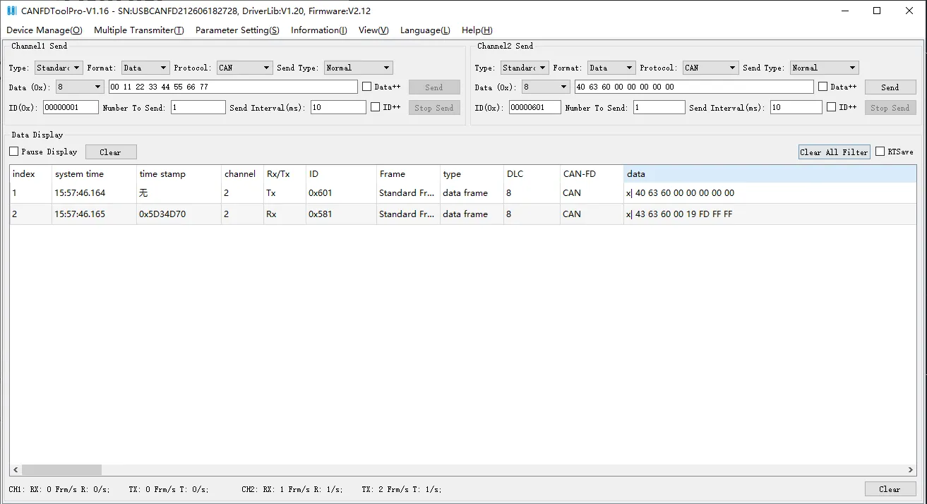
Modify Parameters
| Identifier | DLC | Data | ||||||||
|---|---|---|---|---|---|---|---|---|---|---|
| 0 | 1 | 2 | 3 | 4 | 5 | 6 | 7 | |||
| Transmit SDO Message | 0x600+Node_ID | 8 | Transmit Command Code | Object Index | Object SubIndex | Up to 4-byte Data | ||||
| Receive SDO Message | 0x580+Node_ID | 8 | Receive Command Code | Object Index | Object SubIndex | Up to 4-byte Data | ||||
- Transmit Command Code:
0x2F- 1-byte transmit data;0x2B- 2-byte transmit data;0x23- 4-byte transmit data - Receive Command Code:
0x60- Message transmitted successfully;0x80- Message transmission failed - Example: Control the axis of motor #1 (
0x604000) via SDO. First write0x06to power-off and release the motor shaft, then write0x0Fto power-on and lock the motor shaft.Identifier Command Code Object Index Object SubIndex Up to 4-byte Data 1st Transmitted Message 0x601 0x2B 0x40 0x60 0x00 0x06 0x00 0x00 0x00 1st Received Message 0x581 0x60 0x40 0x60 0x00 0x06 0x00 0x00 0x00 2nd Transmitted Message 0x601 0x2B 0x40 0x60 0x00 0x0F 0x00 0x00 0x00 2nd Received Message 0x581 0x60 0x40 0x60 0x00 0x0F 0x00 0x00 0x00 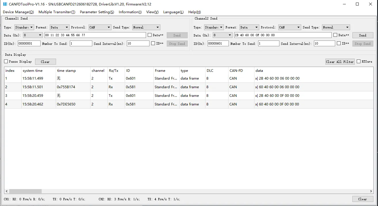
PDO Function
The drive provides a simplified built-in PDO function and requires no configuration from the CAN master station.
| PDO1 Message Format | |||||||||
|---|---|---|---|---|---|---|---|---|---|
| Identifier | DLC | Data | |||||||
| 0 | 1 | 2 | 3 | 4 | 5 | 6 | 7 | ||
| 0x180+Node_ID | 8 | Mapped to Object 0x60F919 (Actual Speed, 0.001 rpm) | Mapped to Object 0x606300 (Actual Position) | ||||||
CAN Communication Examples
Example 1: Read motor actual current Iq
Refer to "Table F1-3 Measured Data" in the Common-use Object List. The object address for "Actual Current Iq" is 0x607800, which is a 16-bit signed number.
Assume the motor actual current is 1 Arms. Conversion formula: [DEC] = [Arms] * 1.414 * 2048 / 15. 1 Arms = 193 (DEC) = 0xC1 (HEX)
| Identifier | Command Code | Object Index | Object SubIndex | Up to 4-byte Data | |||||
|---|---|---|---|---|---|---|---|---|---|
| Host-Sent Message | 0x601 | 0x40 | 0x78 | 0x60 | 0x00 | 0x00 | 0x00 | 0x00 | 0x00 |
| Drive Response Message | 0x581 | 0x4B | 0x78 | 0x60 | 0x00 | 0xC1 | 0x00 | 0x00 | 0x00 |
Example 2: Write Target Speed (High-resolution speed command)
Refer to "Table F1-2 Operating Modes & Control" in the Common-use Object List. The object address for "Target Speed" is 0x60FF00, which is a 32-bit signed number.
Set the speed command to 150 rpm. Conversion formula U[y,x]: [DEC] = ([rpm] * 512 * [Feedback Resolution]) / 1875
Where [Feedback Resolution] = 4096. [DEC] = (150 * 512 * 4096) / 1875 = 167772 → Hex = 0x28F5C
| Identifier | Command Code | Object Index | Object SubIndex | Up to 4-byte Data | |||||
|---|---|---|---|---|---|---|---|---|---|
| Host-Sent Message | 0x601 | 0x23 | 0xFF | 0x60 | 0x00 | 0x5C | 0x8F | 0x02 | 0x00 |
| Drive Response Message | 0x581 | 0x60 | 0xFF | 0x60 | 0x00 | 0x5C | 0x8F | 0x02 | 0x00 |
Example 3: CAN-PDO Communication Example
-
Enable PDO
Refer to "Table F1-5 Communication Parameters" in the Common-use Object List. The object address for "Enable PDO" is0x470001, which is an 8-bit unsigned number.Identifier Command Code Object Index Object SubIndex Up to 4-byte Data Host-Sent Message 0x601 0x2F 0x00 0x47 0x01 0x01 0x00 0x00 0x00 Drive Response Message 0x581 0x60 0x00 0x47 0x01 0x01 0x00 0x00 0x00 -
The slave drive will actively report actual speed and actual position
If the motor actual speed = 10 rpm (Hex:0x2710), and actual position = 1000 DEC (Hex:0x3E8)
The drive transmits messages periodically (default interval: 10 ms).Identifier Command Code Object Index Object SubIndex Up to 4-byte Data Drive-Initiated Message 0x181 0x10 0x27 0x00 0x00 0xE8 0x03 0x00 0x00