SPI Interface
SPI (Serial Peripheral Interface) is a commonly used synchronous serial communication interface, widely adopted for data transfer between microcontrollers (MCUs) and small LCD displays.
Key characteristics:
- Simple interface, low pin count: typically requires only a few IO pins (SCLK, MOSI, CS, DC), ideal for IO-constrained systems
- Low implementation cost: straightforward hardware connections with no complex interface circuitry
- Easy to drive: MCU can directly control display content, enabling custom UI development
- Suited for small displays: commonly used with low-resolution, small-size screens (typically 1–4 inches)
SPI Communication Protocol
SPI LCDs typically support one-way data transfer from host to display only (no MISO line); communication is unidirectional (Master → Slave).
Common interface signals:
- RESX: Reset signal — pull low to reset at power-on, keep high during normal operation
- CSX: Chip select — chip is selected when low
- D/CX: Data/Command control (0 = command, 1 = data)
- SDA: Data input (MOSI)
- SCL: Clock signal
The SPI timing is determined by CPOL and CPHA. These devices typically operate in SPI Mode 0 (CPOL = 0, CPHA = 0): clock idles low, data is sampled on the first rising edge.
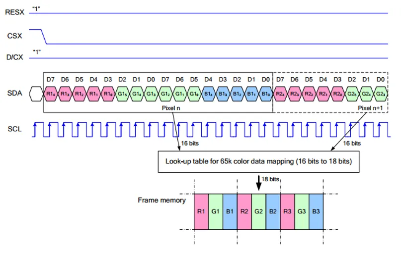
Unlike standard SPI, SPI LCDs are display-only, so the slave-to-master data path (MISO) is omitted. Refer to the corresponding datasheet for details.
Data is transmitted bit-serially, with 1 bit per clock cycle and 8 bits per byte, MSB first.
Depending on the D/CX level, transmitted content is either:
- Command (D/CX = 0): register configuration and initialization
- Data (D/CX = 1): display content (e.g., RGB pixel data)