Working with Arduino
This chapter introduces the Arduino development environment for the ESP32-C5-Pico and the example programs provided in examples/Arduino/examples.
Setting Up the Development Environment
1. Install Arduino IDE and ESP32 Board Support Package
Please refer to the tutorial Install and Configure Arduino IDE to download and install the Arduino IDE and add ESP32 support.
After installing Arduino IDE, add the Espressif Arduino-ESP32 board index in "Preferences -> Additional Boards Manager URLs", and install the Arduino-ESP32 version that supports ESP32-C5 via the "Boards Manager". After installation, select ESP32C5 Dev Module in "Tools -> Board".
Connect the board via USB and select the corresponding serial port in "Tools -> Port". Unless otherwise noted, all examples in this directory use the serial monitor with baud rate set to 115200.
Arduino support for ESP32-C5 depends on the board package version. If the ESP32-C5 board option is not available in the IDE, please upgrade the Espressif Arduino-ESP32 board package first before compiling the examples.
2. Open an Example
Each example directory contains a .ino main file with the same name as the directory. Open that .ino file with the Arduino IDE to compile and upload. 06_Pico_CAN_SoftSPI also contains .cpp and .h files in the same directory; these files must remain in the same sketch directory as the main .ino.
Installing the Libraries
00_Board_Info, 01_WS2812_RGB, 02_TCA9554_IO_Expander, 03_WiFi_DualBand, 04_UART_Loopback, and 06_Pico_CAN_SoftSPI only depend on the components provided by the Arduino-ESP32 board package.
05_1.83inch_Touch_LCD_LVGL_GFX requires the following graphics libraries. This project already provides matching versions in examples/Arduino/libraries; it is recommended to use the libraries from this directory to avoid API version mismatches.
| Library | Version | Purpose | Installation Method |
|---|---|---|---|
lvgl | 8.4.0 | Graphics UI and touch input | Copy libraries/lvgl to the Arduino libraries folder |
GFX Library for Arduino | 1.6.5 | ST7789 display driver | Copy libraries/GFX_Library_for_Arduino to the Arduino libraries folder |
You can install the library packages via "Sketch -> Include Library -> Add .ZIP Library" in the Arduino IDE, or copy the two directories above to the libraries folder under your Arduino Sketchbook and restart the IDE.
The touchscreen example is written based on LVGL 8.4.0 display and input device APIs and cannot be directly switched to LVGL 9. Please use LVGL 8.4.0 and Arduino_GFX 1.6.5 from the project simultaneously.
Example
The example programs are located in this directory. Examples with external interfaces require connecting the corresponding devices or buses before running.
| Example | Description |
|---|---|
| 00_Board_Info | Prints ESP32-C5 chip, Flash, program, and memory information via serial. |
| 01_WS2812_RGB | Controls the onboard WS2812 RGB LED to cycle through red, green, blue, white, and off. |
| 02_TCA9554_IO_Expander | Detects the onboard TCA9554 and sequentially drives the 6 accessible expansion I/O pins. |
| 03_WiFi_DualBand | Scans Wi-Fi networks, displays channel and band, and can connect to a specified network. |
| 04_UART_Loopback | Uses UART1 to send and receive data for a serial loopback test. |
| 05_1.83inch_Touch_LCD_LVGL_GFX | Drives the onboard 1.83inch touchscreen, performs color self-test, and touch drawing. |
| 06_Pico_CAN_SoftSPI | Drives MCP2515 via software SPI to demonstrate 125 kbit/s CAN transceiver operation. |
00_Board_Info
The program prints chip model, chip revision, CPU frequency, Flash size, compiled program size, remaining heap memory, and base MAC address after startup, then stays running. This example requires no extra hardware and is the preferred first test for verifying board connection, upload, and serial configuration.

01_WS2812_RGB
The onboard WS2812 RGB LED data pin is GPIO27. The program uses the Arduino-ESP32 rgbLedWriteOrdered() interface, sets brightness to 32, and toggles between red, green, blue, white, and off every second; the serial port simultaneously outputs the current RGB value.
This example does not rely on third-party libraries. If the LED color does not match expectations, check whether COLOR_ORDER needs to match the actual color order of the LED.

02_TCA9554_IO_Expander
The onboard TCA9554 I/O expander uses I2C with the following configuration:
| Signal | ESP32-C5-Pico Pin |
|---|---|
| SDA | GPIO23 |
| SCL | GPIO24 |
| I2C addr | 0x20 |
| Bus freq | 100 kHz |
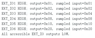
The program first detects the device at address 0x20, then configures the expander as outputs and sequentially drives EXT_IO1 through EXT_IO6 high, each for 1 second. You can observe the expansion I/O headers with a multimeter or logic analyzer. If detection fails, check the onboard device and I2C pin connections.
03_WiFi_DualBand
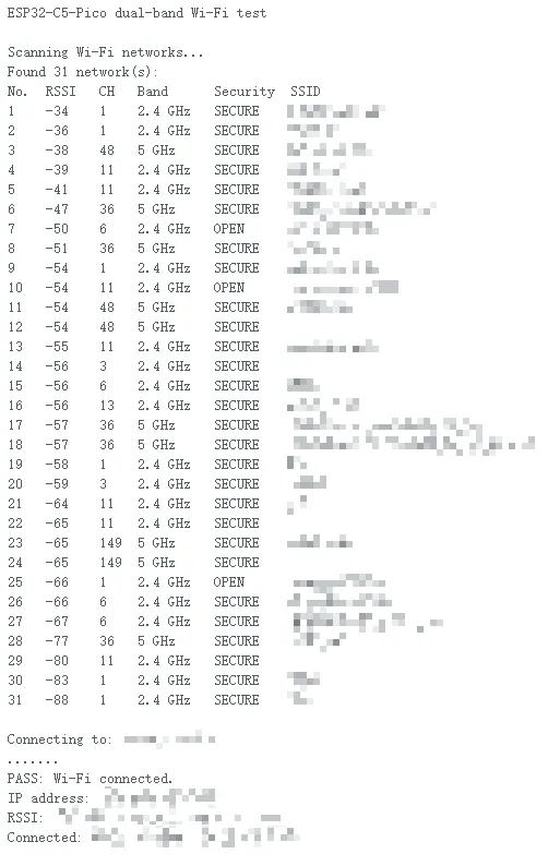
This example configures the chip in STA mode, scans available networks, and lists RSSI, channel, security status, and band via serial: channels 1 to 14 are marked as 2.4 GHz, others as 5 GHz.
To test network connectivity, first modify the configuration at the top of the source code:
static const char *WIFI_SSID = "MySID";
static const char *WIFI_PASSWORD = "MyPassWord";
After uploading, the program waits up to 20 seconds to connect to the specified Wi-Fi and prints the IP address, RSSI, channel, and band; if the connection drops, it rescans networks.
04_UART_Loopback
This example uses UART1 for a self-loopback test with the following initialization:
| Signal | GPIO | Parameters |
|---|---|---|
| UART1 TX | GPIO0 | 115200, 8N1 |
| UART1 RX | GPIO1 | 115200, 8N1 |
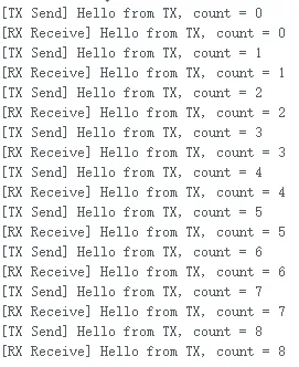
Connect GPIO0 to GPIO1 with a wire and upload the program. The program sends an incrementing count message via TX every two seconds, and prints [RX Receive] when it receives the same message on RX.
05_1.83inch_Touch_LCD_LVGL_GFX
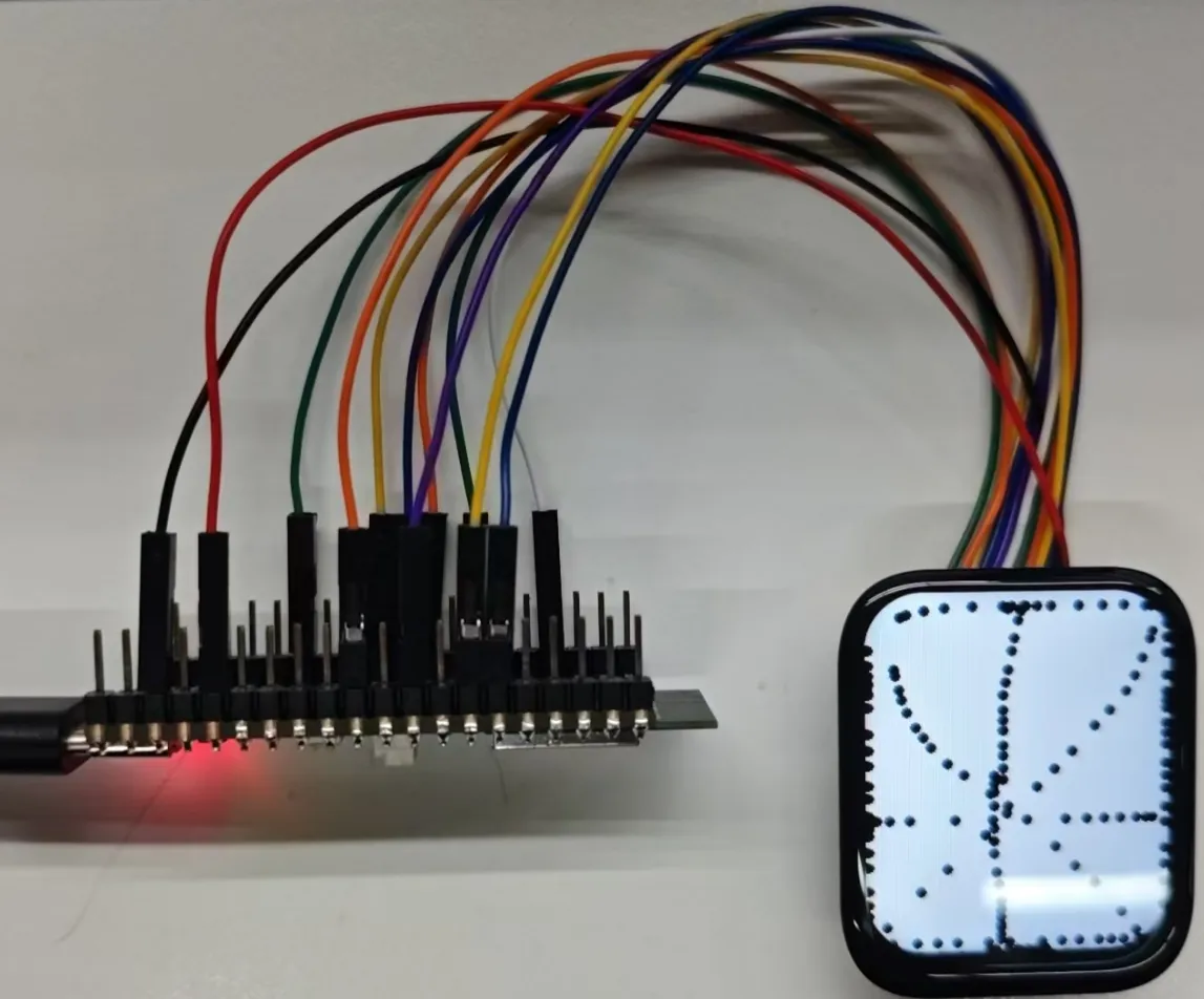
This example uses Arduino_GFX to drive a 240 x 284 1.83inch Touch LCD and uses LVGL 8.4.0 to set up the display and touch input device. The touch controller is CST816 and the display controller is ST7789.
| Function | Signal | GPIO / Address |
|---|---|---|
| LCD software SPI | SCLK / MOSI / CS / DC / RST / BL | 7 / 8 / 9 / 10 / 15 / 25 |
| Touch I2C | SDA / SCL | GPIO23 / GPIO24 |
| Touch control | RST / INT | GPIO26 / GPIO5 |
| CST816 address | I2C | 0x15 |
| TCA9554 address | I2C | 0x20 |
On startup, the program blinks the backlight, scans the I2C bus, displays five solid colors (red, yellow, blue, green, white) in sequence, and then initializes LVGL. After entering the main screen, you can draw black dots on a white canvas via touch. Before compiling, install LVGL and Arduino_GFX according to the versions listed in Installing the Libraries.
06_Pico_CAN_SoftSPI
Because the MCP2515 SCK uses GPIO6 by default, but the onboard GPIO6 is used for battery ADC detection. If you need to connect the Pico-CAN-B, you must disconnect GPIO6 from BAT_ADC.
Connect the Pico-CAN-B device to the ESP32-C5-Pico.
Power up after connecting Pico-CAN-B to USB-CAN-A.
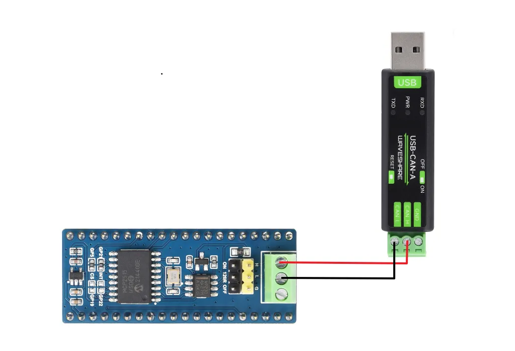
| MCP2515 Signal | ESP32-C5-Pico GPIO |
|---|---|
| SCK | GPIO6 |
| MISO | GPIO4 |
| MOSI | GPIO7 |
| CS | GPIO5 |
The program configures the MCP2515 for 125 kbit/s @ 16 MHz, normal mode, and receives all messages. It sends a standard frame every second: CAN ID 0x123, data 00 11 22 33 44 55 66 77; when a message is received, it prints the received ID and data via serial.
MCP2515 is only a CAN controller; it must be used with a CAN transceiver and proper termination resistors on the CAN bus. The rate configuration in this example is only valid for a 16 MHz MCP2515 module; register parameters must be modified if using a different crystal frequency.
-
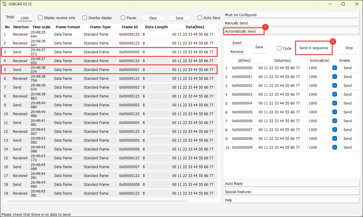
Data reception: debug with USB-CAN-A_TOOL
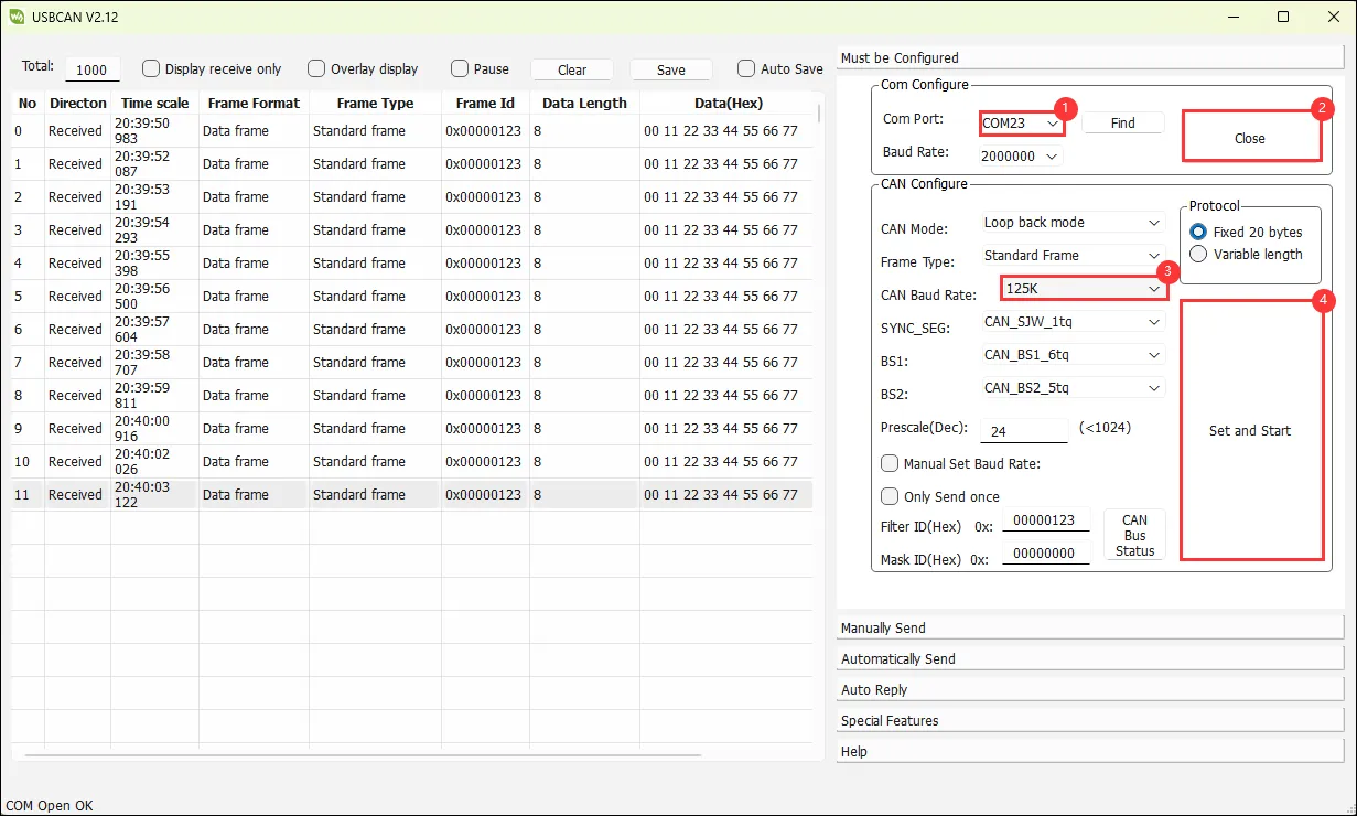
-
Data transmission: view printed data via a serial debug assistant (also viewable with the Arduino serial monitor)
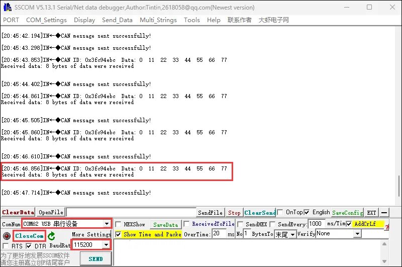
Common Issues
ESP32-C5 board not found
Update the Arduino-ESP32 board package and make sure you have selected a version that supports ESP32-C5; older board packages will not show the ESP32-C5 option.
Touchscreen example fails to compile
Make sure you have installed lvgl 8.4.0 and GFX Library for Arduino 1.6.5 from the project, and that they are not being overridden by other versions with the same names in the Arduino Sketchbook.
Wi-Fi example cannot connect
Make sure you have changed WIFI_SSID and WIFI_PASSWORD to your actual network credentials, and that your network allows the band used by the ESP32-C5. The scan results from the serial can be used to confirm whether the target network is visible.
CAN no communication
First check that the GPIO wiring matches the table on this page, then verify the external transceiver, power, bus polarity, and termination configuration. The CAN example assumes a 16 MHz MCP2515.