Working with Arduino
This chapter includes the following sections. Please read as needed:
Arduino Getting Started
New to Arduino ESP32 development and looking for a quick start? We have prepared a comprehensive Getting Started Tutorial for you.
- Section 0: Getting to Know ESP32
- Section 1: Installing and Configuring Arduino IDE
- Section 2: Arduino Basics
- Section 3: Digital Output/Input
- Section 4: Analog Input
- Section 5: Pulse Width Modulation (PWM)
- Section 6: Serial Communication (UART)
- Section 7: I2C Communication
- Section 8: SPI Communication
- Section 9: Wi-Fi Basics
- Section 10: Web Server
- Section 11: Bluetooth
- Section 12: LVGL GUI Development
- Section 13: Comprehensive Project
Note: This tutorial uses the ESP32-S3-Zero as a reference example, and all hardware code is based on its pinout. Before you start, we recommend checking the pinout of your development board to ensure the pin configuration is correct.
Setting Up the Development Environment
Install Arduino IDE
Please refer to the Install and Configure Arduino IDE Tutorial to install the Arduino IDE and add ESP32 board support.
Select Board and Port
After connecting the ESP32-C5-Touch-LCD-1.69 to your computer, select the corresponding serial port in the "Tools" menu.
Install Example Libraries
The Arduino examples are located in the example/arduino/examples directory. Before running an example, first extract example/arduino/ESP32_C5_Touch_LCD_1in69.zip, then copy the extracted library into the Arduino default libraries directory.
The Arduino libraries folder is typically located at:
C:/Users/<username>/Documents/Arduino/libraries
You can also check the "Sketchbook location" in Arduino IDE via "File > Preferences", and find the libraries folder under that path.
Example
| Example | Basic Description |
|---|---|
| 01_RGB_Test | Screen color cycling test |
| 02_Mic_Speaker_Test | Microphone and speaker test |
| 03_IMU_Test | IMU test |
| 04_Bat_Test | Battery detection test |
| 05_RTC_Test | RTC test |
| 06_LVGL_Demo_Test | LVGL example test |
01_RGB_Test
Hardware Connection
- Connect the development board to a computer using a USB cable.
Code Analysis
RGB color cycling test code
static const uint16_t Colors[] = {
    0xF800,  // Red
    0x07E0,  // Green
    0x001F,  // Blue
    0xFFFF,  // White
    0x0000,  // Black
};

static const char *ColorNames[] = {
    "R", "G", "B", "W", "BL",
};

void setup(void)
{
    Serial.begin(115200);
    delay(200);

    if (!bsp_display_init()) {
        Serial.println("bsp_display_init failed");
        while (true) {
            delay(1000);
        }
    }

    bsp_display_backlight_on();
    bsp_display_brightness_set(100);
}

void loop(void)
{
    bsp_display_fill(Colors[color_index]);
    Serial.printf("Show color: %s (%u)\n", ColorNames[color_index], color_index);

    color_index++;
    if (color_index >= (sizeof(Colors) / sizeof(Colors[0]))) {
        color_index = 0;
    }

    delay(2000);
}
Code Explanation
Colors[]/ColorNames[]: RGB565 color values and name arrays (red/green/blue/white/black) for cycling through full-screen fills.bsp_display_init(): Initializes the SPI bus and ST7789 LCD panel.bsp_display_backlight_on(): Turns on the LCD backlight.bsp_display_brightness_set(100): Sets backlight brightness to 100%.bsp_display_fill(Colors[color_index]): Fills the entire screen with the specified RGB565 color.Serial.printf(...): Outputs the current color name and index via serial for debugging.
Expected Behavior
- The screen displays pure colors in sequence: red, green, blue, white, black, each for 2 seconds before switching.
- The serial port outputs the current color name and index every 2 seconds.

02_Mic_Speaker_Test
Hardware Connection
- Connect the development board to a computer using a USB cable.
Code Analysis
Microphone loopback playback code
constexpr size_t audio_frame_bytes = 1024;
constexpr uint8_t speaker_volume = 70;
constexpr uint8_t mic_gain_db = 18;

uint8_t audio_buffer[audio_frame_bytes];

void setup()
{
    Serial.begin(115200);

    if (!bsp_audio_init()) {
        Serial.println("bsp_audio_init failed");
        return;
    }

    bsp_audio_set_speaker_volume(speaker_volume);
    bsp_audio_set_mic_gain(mic_gain_db);

    Serial.println("microphone loopback to speaker");
}

void loop()
{
    size_t bytes_read = 0;
    size_t bytes_written = 0;

    if (!bsp_audio_read(audio_buffer, sizeof(audio_buffer), &bytes_read) || (bytes_read == 0)) {
        Serial.println("bsp_audio_read failed");
        delay(10);
        return;
    }

    if (!bsp_audio_write(audio_buffer, bytes_read, &bytes_written) || (bytes_written != bytes_read)) {
        Serial.println("bsp_audio_write failed");
        delay(10);
    }
}
Code Explanation
bsp_audio_init(): Initializes the I2S bus and ES8311 codec.bsp_audio_set_speaker_volume(70): Sets speaker volume to 70.bsp_audio_set_mic_gain(18): Sets microphone gain to 18dB.bsp_audio_read(audio_buffer, ...): Reads 1024 bytes of audio data from the microphone.bsp_audio_write(audio_buffer, ...): Writes the read audio data to the speaker, implementing real-time loopback.
Expected Behavior
- Serial output shows
microphone loopback to speaker. - Speaking into the microphone allows real-time playback from the speaker.
03_IMU_Test
Hardware Connection
- Connect the development board to a computer using a USB cable.
Code Analysis
QMI8658 initialization and data reading code
#define QMI8658_I2C_ADDRESS 0x6B

static QMI8658 imu(Wire);
static AccelData accel_data = { 0 };
static GyroData gyro_data = { 0 };

void setup(void)
{
    Serial.begin(115200);

    bsp_display_brightness_init();
    bsp_display_brightness_set(100);

    if (!bsp_i2c_init()) {
        Serial.println("I2C init failed");
        while (true) {
            delay(1000);
        }
    }

    imu.init(imu_calibration, QMI8658_I2C_ADDRESS);
    imu.setAccelRange(8);
    imu.setGyroRange(512);
    imu.setAccelODR(1000);
    imu.setGyroODR(1000);

    Serial.println("QMI8658 ready");
}

void loop(void)
{
    imu.update();
    imu.getAccel(&accel_data);
    imu.getGyro(&gyro_data);

    Serial.print("ACC[g] ");
    Serial.print(accel_data.accelX, 3);
    Serial.print(", ");
    Serial.print(accel_data.accelY, 3);
    Serial.print(", ");
    Serial.print(accel_data.accelZ, 3);
    Serial.print("  GYRO[dps] ");
    Serial.print(gyro_data.gyroX, 3);
    Serial.print(", ");
    Serial.print(gyro_data.gyroY, 3);
    Serial.print(", ");
    Serial.print(gyro_data.gyroZ, 3);
    Serial.print("  TEMP[C] ");
    Serial.println(imu.getTemp(), 2);

    delay(100);
}
Code Explanation
bsp_i2c_init(): Initializes the I2C bus (SDA=GPIO8, SCL=GPIO9, 400kHz).imu.init(imu_calibration, QMI8658_I2C_ADDRESS): Initializes the QMI8658 with I2C address 0x6B.imu.setAccelRange(8)/imu.setGyroRange(512): Sets accelerometer range to ±8g and gyroscope range to ±512dps.imu.setAccelODR(1000)/imu.setGyroODR(1000): Sets accelerometer and gyroscope output data rate to 1000Hz.imu.update(): Updates sensor data.imu.getAccel(&accel_data)/imu.getGyro(&gyro_data): Reads accelerometer and gyroscope data.imu.getTemp(): Reads temperature data.
Expected Behavior
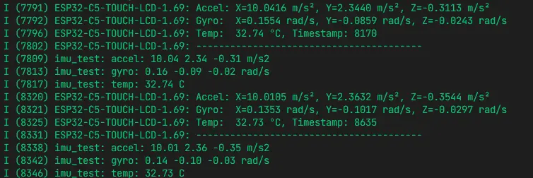
- After serial output
QMI8658 ready, it prints accelerometer (g), gyroscope (dps), and temperature (°C) data every 100ms. - When the development board is slightly tilted or rotated, the accelerometer and gyroscope data will change accordingly.
04_Bat_Test
Hardware Connection
- Connect the development board to a computer using a USB cable.
- Connect a Lithium battery to the development board.
Code Analysis
Battery information reading and display code
static const uint16_t battery_capacity_mah = 1500;

static const bsp_display_lvgl_partial_cfg_t battery_display_cfg = {
    .use_psram = false,
    .double_buffer = false,
    .buffer_height = 120,
};

static void bat_update_label(const bsp_bat_info_t *bat_info)
{
    const char *battery_state = "Idle";
    const char *battery_note = "";

    battery_state = (bat_info->ma > 0) ? "Charging" : ((bat_info->ma < 0) ? "Discharging" : "Idle");
    battery_note = (bat_info->ma == 0) ? "battery not connected or full" : "battery connected";

    lv_label_set_text_fmt(battery_label,
        "Battery Test\n"
        "State: %s\n"
        "Voltage: %u mV\n"
        "Current: %d mA\n"
        "SOC: %u %%\n"
        "Temp: %d C\n"
        "Capacity: %u mAh\n"
        "%s",
        battery_state,
        bat_info->mv,
        bat_info->ma,
        bat_info->soc,
        bat_info->tc,
        battery_capacity_mah,
        battery_note);
}

void setup(void)
{
    bsp_display_start_partial(&battery_display_cfg);
    bsp_display_brightness_set(100);
    bsp_bat_init(battery_capacity_mah);

    bsp_display_lock(0);
    battery_label = lv_label_create(lv_scr_act());
    lv_obj_align(battery_label, LV_ALIGN_TOP_LEFT, 10, 10);
    lv_label_set_text(battery_label, "Battery Test\nBattery status updating");
    bsp_display_unlock();
}

void loop(void)
{
    bsp_bat_info_t bat_info = {};

    if (!bsp_get_bat_info(&bat_info)) {
        Serial.println("battery info update failed");
        return;
    }

    if (bat_info_changed(&battery_last_info, &bat_info)) {
        if (bsp_display_lock(0)) {
            bat_update_label(&bat_info);
            battery_last_info = bat_info;
            bsp_display_unlock();
        }
    }

    delay(1000);
}
Code Explanation
bsp_display_start_partial(&battery_display_cfg): Starts LVGL in partial refresh mode to reduce framebuffer memory usage.bsp_bat_init(battery_capacity_mah): Initializes the BQ27220 fuel gauge with battery capacity set to 1500mAh.bsp_get_bat_info(&bat_info): Reads battery information (voltage/current/SOC/temperature, etc.).bsp_display_lock(0)/bsp_display_unlock(): Acquires/releases the LVGL mutex for thread safety.lv_label_set_text_fmt(battery_label, ...): Formats and updates the battery information label.bat_info_changed(...): Checks whether battery data has changed to avoid unnecessary refreshes.
Expected Behavior
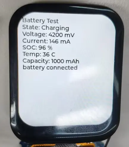
- The screen displays battery status information: State (Charging/Discharging/Idle), Voltage (mV), Current (mA), SOC (%), Temperature (°C), Capacity (mAh).
- Serial output also shows battery data.
- When a battery is connected and current is non-zero, the state shows Charging or Discharging; when no battery is connected or fully charged, it shows Idle.
05_RTC_Test
Hardware Connection
- Connect the development board to a computer using a USB cable.
Code Analysis
RTC initialization and time reading code
static PCF85063A rtc(Wire);
static void rtc_set_to_build_time(void)
{
struct tm now_tm = {};
const char *build_date = __DATE__;
const char *build_time = __TIME__;
now_tm.tm_year = ((build_date[7] - '0') * 1000 + (build_date[8] - '0') * 100 +
(build_date[9] - '0') * 10 + (build_date[10] - '0')) - 1900;
now_tm.tm_mon = month_from_build_date(build_date);
now_tm.tm_mday = (build_date[4] == ' ') ? (build_date[5] - '0')
: ((build_date[4] - '0') * 10 + (build_date[5] - '0'));
now_tm.tm_hour = (build_time[0] - '0') * 10 + (build_time[1] - '0');
now_tm.tm_min = (build_time[3] - '0') * 10 + (build_time[4] - '0');
now_tm.tm_sec = (build_time[6] - '0') * 10 + (build_time[7] - '0');
rtc.set(&now_tm);
}
void setup(void)
{
Serial.begin(115200);
bsp_display_brightness_init();
bsp_display_brightness_set(100);
bsp_i2c_init();
rtc.begin();
if (rtc.oscillator_stop()) {
Serial.println("RTC lost power, set to build time");
rtc_set_to_build_time();
} else {
Serial.println("RTC running");
}
}
void loop(void)
{
time_t current_time = rtc.time(NULL);
struct tm *now_tm = localtime(¤t_time);
Serial.printf("%04d-%02d-%02d %02d:%02d:%02d\r\n",
now_tm->tm_year + 1900,
now_tm->tm_mon + 1,
now_tm->tm_mday,
now_tm->tm_hour,
now_tm->tm_min,
now_tm->tm_sec);
delay(1000);
}
Code Explanation
bsp_i2c_init(): Initializes the I2C bus.rtc.begin(): Initializes the PCF85063A RTC chip.rtc.oscillator_stop(): Checks whether the RTC oscillator has stopped (power loss); returns true if time is lost.rtc_set_to_build_time(): Sets RTC time using the compile time (__DATE__/__TIME__).rtc.time(NULL): Reads the RTC timestamp.localtime(¤t_time): Converts timestamp to local time structure for formatted output.
Expected Behavior
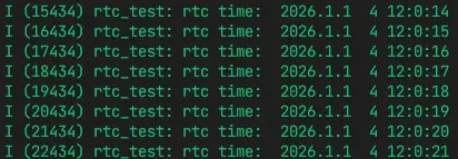
- Serial output shows
RTC runningorRTC lost power, set to build time. - Then outputs time in
YYYY-MM-DD HH:MM:SSformat every second.
06_LVGL_Demo_Test
Hardware Connection
- Connect the development board to a computer using a USB cable.
Code Analysis
LVGL Benchmark initialization code
static const bsp_display_lvgl_full_frame_cfg_t lgvl_config = {
    .use_psram = true,
    .double_buffer = true,
    .full_refresh = true,
};

void setup(void)
{
    Serial.begin(115200);
    bsp_display_start_full_frame(&lgvl_config);
    bsp_display_brightness_set(100);

    bsp_display_lock(0);
    lv_demo_benchmark_set_max_speed(true);
    lv_demo_benchmark();
    bsp_display_unlock();
}

void loop(void)
{
    delay(1000);
}
Code Explanation
bsp_display_start_full_frame(&lgvl_config): Starts LVGL in full-frame mode with PSRAM, double buffering, and full refresh enabled for best display performance.bsp_display_brightness_set(100): Sets backlight brightness to 100%.bsp_display_lock(0)/bsp_display_unlock(): Acquires/releases the LVGL mutex for thread-safe UI operations.lv_demo_benchmark_set_max_speed(true): Sets benchmark to maximum speed mode.lv_demo_benchmark(): Starts the LVGL benchmark performance test.
Expected Behavior
- The screen sequentially displays various LVGL benchmark test scenes (rectangle, shadow, text, image, animation, and other rendering performance tests).
- After the test completes, a summary of FPS scores is displayed.