Working with Arduino
This chapter contains the following sections. Please read as needed:
Arduino Getting Started
New to Arduino ESP32 development and looking for a quick start? We have prepared a comprehensive Getting Started Tutorial for you.
- Section 0: Getting to Know ESP32
- Section 1: Installing and Configuring Arduino IDE
- Section 2: Arduino Basics
- Section 3: Digital Output/Input
- Section 4: Analog Input
- Section 5: Pulse Width Modulation (PWM)
- Section 6: Serial Communication (UART)
- Section 7: I2C Communication
- Section 8: SPI Communication
- Section 9: Wi-Fi Basics
- Section 10: Web Server
- Section 11: Bluetooth
- Section 12: LVGL GUI Development
- Section 13: Comprehensive Project
Note: This tutorial uses the ESP32-S3-Zero as a reference example, and all hardware code is based on its pinout. Before you start, we recommend checking the pinout of your development board to ensure the pin configuration is correct.
Setting Up Development Environment
1. Installing and Configuring Arduino IDE
Please refer to the tutorial Installing and Configuring Arduino IDE to download and install the Arduino IDE and add ESP32 support.
2. Installing Libraries
To run the demo, you need to install the corresponding library.
| Library/File Name | Description | Version | Installation Method |
|---|---|---|---|
| lvgl | lvgl graphical library | v8.4.0 or v9.2.2 | "Install Online" |
| GFX Library for Arduino | GFX graphical library | v1.6.0 | "Install Online" |
| SensorLib | Sensor library | v0.3.1 | "Install Online" |
There are strong dependencies between versions of LVGL and its driver libraries. For example, a driver written for LVGL v8 may not be compatible with LVGL v9. To ensure that the examples can be reproduced reliably, it is recommended to use the specific versions listed in the table above. Mixing different versions of libraries may lead to compilation failures or runtime errors.
Installation Steps: For installation methods, please refer to: Arduino Library Management Tutorial.
Demo
The Arduino demos are located in the Arduino directory of the demo package.
| Demo | Basic Description |
|---|---|
| 01_GPIO | Controls a total of 20 specified GPIO pins to cycle through HIGH/LOW level switching in sequence, and prints the level change status of each pin via serial port |
| 02_BlinkRGB | Controls an RGB LED to create a waterfall light dynamic effect |
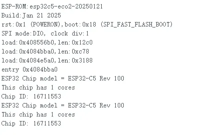
| 03_GetchipID | Retrieves and prints ESP32-C5 chip hardware information (chip model, revision, core count, chip ID) every three seconds |
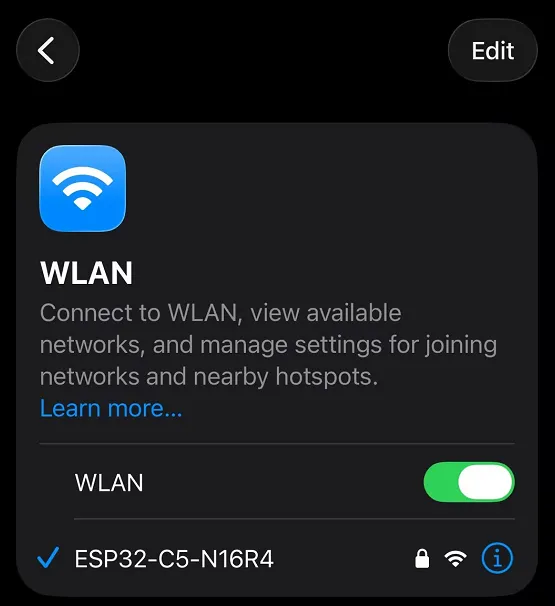
| 04_WIFI_AP | Configures the ESP32-C5-N16R4 development board as a WiFi Access Point (2.4G), allowing other WiFi devices to connect |
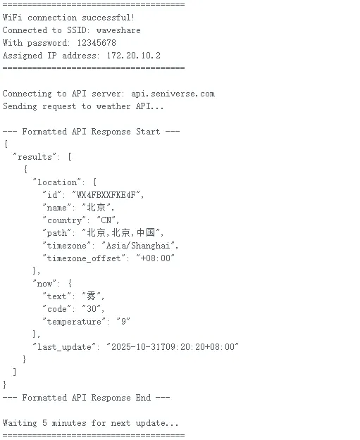
| 05_WIFI_STA | Connects to a specified WiFi network, prints connection info, calls the OpenWeather API every 5 minutes to fetch and print formatted data, and supports automatic WiFi reconnection |
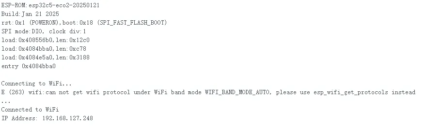
| 06_WIFI_DHCP | Connects to a WiFi network using the ESP32-C5-N16R4 development board and obtains an IP address via DHCP |
| 07_WIFI_StaticIP | Connects to a WiFi network using the ESP32-C5-N16R4 development board with a statically assigned IP address |
| 08_lvgl8.4.0_demo | Demonstrates text effects on a 2.4inch LCD Module |
| 09_lvgl9.2.2_demo | Demonstrates text effects on a 2.4inch LCD Module |
01_GPIO
This program controls the levels of a total of 20 specified GPIO pins. The left 11 pins cycle sequentially through "HIGH → LOW" switching, and the right 9 pins cycle sequentially through "LOW → HIGH" switching. Each level state lasts 300 milliseconds, and the level change status of each pin is printed in real-time via the serial port.

Code
01_GPIO.ino
/*
  author: liangjingheng
  date: 2025-10-14
  company: waveshare
*/
#define NUM_LEFT 11  // Number of left GPIO pins
#define NUM_RIGHT 9 // Number of right GPIO pins

// Left GPIO pins
const int left_gpios[NUM_LEFT] = {0, 1, 2, 3, 6, 7, 8, 9, 10, 25, 26};
// Right GPIO pins
const int right_gpios[NUM_RIGHT] = {24, 23, 15, 27, 5, 4, 28, 14, 13};

void setup() {
  Serial.begin(115200); // Initialize serial port (for printing information)

  // Initialize left GPIOs: output mode, default low level
  for (int i = 0; i < NUM_LEFT; i++) {
    pinMode(left_gpios[i], OUTPUT);
    digitalWrite(left_gpios[i], LOW);
    Serial.printf("Left GPIO %d initialized to LOW.\n", left_gpios[i]);
  }

  // Initialize right GPIOs: output mode, default high level
  for (int i = 0; i < NUM_RIGHT; i++) {
    pinMode(right_gpios[i], OUTPUT);
    digitalWrite(right_gpios[i], HIGH);
    Serial.printf("Right GPIO %d initialized to HIGH.\n", right_gpios[i]);
  }
}

void loop() {
  // Left GPIOs: HIGH → LOW (execute one by one)
  for (int i = 0; i < NUM_LEFT; i++) {
    digitalWrite(left_gpios[i], HIGH);
    Serial.printf("Left GPIO %d set to HIGH.\n", left_gpios[i]);
    delay(300); // Delay for 300ms to ensure visibility of the effect

    digitalWrite(left_gpios[i], LOW);
    Serial.printf("Left GPIO %d set to LOW.\n", left_gpios[i]);
    delay(300);
  }

  // Right GPIOs: LOW → HIGH (execute one by one)
  for (int i = 0; i < NUM_RIGHT; i++) {
    digitalWrite(right_gpios[i], LOW);
    Serial.printf("Right GPIO %d set to LOW.\n", right_gpios[i]);
    delay(300);

    digitalWrite(right_gpios[i], HIGH);
    Serial.printf("Right GPIO %d set to HIGH.\n", right_gpios[i]);
    delay(300);
  }
}
Code Analysis
-
setup()function:- Initializes Serial: Configures the serial port baud rate to 115200 via
Serial.begin(115200)for printingGPIOstatus information. - Configures Left
GPIO: Iterates through an array containing 11 pins (0, 1, 2, 3, 6, 7, 8, 9, 10, 25, 26), sets each pin to output mode with a default low level, and prints the initialization status. - Configures Right
GPIO: Iterates through an array containing 9 pins (24, 23, 15, 27, 5, 4, 28, 14, 13), sets each pin to output mode with a default high level, and prints the initialization status.
- Initializes Serial: Configures the serial port baud rate to 115200 via
-
loop()function:- Controls Left
GPIO: Switches each pin sequentially from LOW to HIGH, prints the status, then delays 300ms; switches it back to LOW, prints the status, then delays another 300ms. - Controls Right
GPIO: Switches each pin sequentially from HIGH to LOW, prints the status, then delays 300ms; switches it back to HIGH, prints the status, then delays another 300ms.
- Controls Left
02_BlinkRGB
This example demonstrates controlling an RGB LED to create a waterfall light dynamic effect.
Code
02_BlinkRGB.ino
/*
  BlinkRGB

  Demonstrates usage of onboard RGB LED on some ESP dev boards.

  Calling digitalWrite(RGB_BUILTIN, HIGH) will use hidden RGB driver.

  RGBLedWrite demonstrates control of each channel:
  void rgbLedWrite(uint8_t pin, uint8_t red_val, uint8_t green_val, uint8_t blue_val)

  WARNING: After using digitalWrite to drive RGB LED it will be impossible to drive the same pin
    with normal HIGH/LOW level
*/
//#define RGB_BRIGHTNESS 64 // Change white brightness (max 255)

// the setup function runs once when you press reset or power the board

void setup() {
  // No need to initialize the RGB LED
}

// the loop function runs over and over again forever
void loop() {
#ifdef RGB_BUILTIN
  digitalWrite(RGB_BUILTIN, HIGH);  // Turn the RGB LED white
  delay(1000);
  digitalWrite(RGB_BUILTIN, LOW);  // Turn the RGB LED off
  delay(1000);

  rgbLedWrite(RGB_BUILTIN, RGB_BRIGHTNESS, 0, 0);  // Red
  delay(1000);
  rgbLedWrite(RGB_BUILTIN, 0, RGB_BRIGHTNESS, 0);  // Green
  delay(1000);
  rgbLedWrite(RGB_BUILTIN, 0, 0, RGB_BRIGHTNESS);  // Blue
  delay(1000);
  rgbLedWrite(RGB_BUILTIN, 0, 0, 0);  // Off / black
  delay(1000);
#endif
}
Code Analysis
setup()function:- No extra initialization is needed for the RGB LED, as it can be directly driven by subsequent
digitalWriteorrgbLedWritecalls.
- No extra initialization is needed for the RGB LED, as it can be directly driven by subsequent
loop()function:- Implements multi-color switching and on/off control for the RGB LED in a loop. Uses
digitalWrite(RGB_BUILTIN, HIGH)to turn the RGB LED white, delays 1 second, then usesdigitalWrite(RGB_BUILTIN, LOW)to turn it off, followed by another 1-second delay. - Calls the
rgbLedWritefunction to light up red, green, and blue individually, maintaining each color for 1 second. - Finally uses
rgbLedWrite(RGB_BUILTIN, 0, 0, 0)to turn off the RGB LED, delays 1 second, and repeats the entire cycle.
- Implements multi-color switching and on/off control for the RGB LED in a loop. Uses
03_GetchipID
This example retrieves and prints the ESP32 chip's hardware information, including chip model, version, number of cores, and chip ID, every three seconds.
Code
03_GetchipID.ino
/* The true ESP32 chip ID is essentially its MAC address.
This sketch provides an alternate chip ID that matches
the output of the ESP.getChipId() function on ESP8266
(i.e. a 32-bit integer matching the last 3 bytes of
the MAC address. This is less unique than the
MAC address chip ID, but is helpful when you need
an identifier that can be no more than a 32-bit integer
(like for switch...case).

created 2020-06-07 by cweinhofer
with help from Cicicok */

uint32_t chipId = 0;

void setup() {
  Serial.begin(115200);
}

void loop() {
  for (int i = 0; i < 17; i = i + 8) {
    chipId |= ((ESP.getEfuseMac() >> (40 - i)) & 0xff) << i;
  }

  Serial.printf("ESP32 Chip model = %s Rev %d\n", ESP.getChipModel(), ESP.getChipRevision());
  Serial.printf("This chip has %d cores\n", ESP.getChipCores());
  Serial.print("Chip ID: ");
  Serial.println(chipId);

  delay(3000);
}
Code Analysis
setup()function:- Initializes Serial Communication: Configures the serial port baud rate to 115200 via
Serial.begin(115200), providing an output channel for subsequent chip information printing.
- Initializes Serial Communication: Configures the serial port baud rate to 115200 via
loop()function:- Prints Chip Information: Calls
ESP.getChipModel(),ESP.getChipRevision(),ESP.getChipCores()to obtain and print chip model, revision, and core count respectively; then prints the calculatedchipId. - Execute Periodically: Repeats the chip ID calculation and information printing process via
delay(3000)every 3 seconds.
- Prints Chip Information: Calls
04_WIFI_AP
This example configures the ESP32-C5-N16R4 development board to create a WiFi hotspot named "ESP32-C5-N16R4" with password "waveshare". It monitors device connection/disconnection status and prints the device's MAC address and assigned IP address via serial port.
Code
04_WIFI_AP.ino
/**
 ******************************************************************************
 * @file     WiFi_AP.ino
 * @brief    ESP32-C5-N16R4 act as WiFi Access Point and monitor client connections
 * @version V1.1
 * @date    2025-10-14
 * @author  liangjingheng
 * @company  Waveshare
 * @license MIT
 ******************************************************************************
 * Enhanced Features:
 * 1. Create WiFi Access Point with specified SSID ("ESP32-C5-N16R4") and password
 * 2. Monitor client connection/disconnection events via WiFi event handler
 * 3. Print connected device's MAC address, assigned IP address via serial port
 * 4. Provide real-time status feedback for network events
 ******************************************************************************
 */

#include <WiFi.h>
#include <esp_wifi.h>  // ESP-IDF library to access connected client info

// WiFi Access Point credentials
const char* ssid     = "ESP32-C5-N16R4";   //your ap name
const char* password = "waveshare";       // your AP password

// Convert MAC address from byte array to readable string (XX:XX:XX:XX:XX:XX)
String formatMacAddress(const uint8_t* mac) {
    char macStr[18];
    snprintf(macStr, sizeof(macStr), "%02X:%02X:%02X:%02X:%02X:%02X",
             mac[0], mac[1], mac[2], mac[3], mac[4], mac[5]);
    return String(macStr);
}

// Handle WiFi events (connection, disconnection, IP assignment)
void WiFiEvent(WiFiEvent_t event, WiFiEventInfo_t info) {
    switch (event) {
        case ARDUINO_EVENT_WIFI_AP_STACONNECTED:
            // Print MAC address when a new device connects to AP
            Serial.println("New device connected:");
            Serial.print("MAC Address: ");
            Serial.println(formatMacAddress(info.wifi_ap_staconnected.mac));
            break;

        case ARDUINO_EVENT_WIFI_AP_STADISCONNECTED:
            // Print message when a device disconnects from AP
            Serial.println("Device disconnected from AP");
            break;

        case ARDUINO_EVENT_WIFI_AP_STAIPASSIGNED:
            // Print IP address assigned to connected device
            Serial.print("Assigned IP to device: ");
            Serial.println(IPAddress(info.got_ip.ip_info.ip.addr));
            break;

        default:
            break;
    }
}

void setup() {
    // Initialize serial communication (115200 baud rate) for debugging
    Serial.begin(115200);

    // Start WiFi Access Point with specified SSID and password
    WiFi.softAP(ssid, password);

    // Register event handler to monitor client connection status
    WiFi.onEvent(WiFiEvent);

    // Short delay to stabilize WiFi AP setup
    delay(1000);

    // Print AP initialization status to serial console
    Serial.println("WiFi Access Point initialized successfully");
    Serial.print("AP SSID: ");
    Serial.println(ssid);
    Serial.print("AP Password: ");
    Serial.println(password);
}

void loop() {
    // No active operation in loop; CPU remains idle
    delay(1000);  // Small delay to reduce unnecessary CPU usage
}
Code Analysis
-
setup():- Initializes Serial: Starts serial communication via
Serial.begin(115200)for printing debug information. - Starts WiFi Access Point: Calls
WiFi.softAP(ssid, password)to set the device to AP mode (SSID: "ESP32-C5-N16R4", password: "waveshare"). - Registers Event Handler: Registers a custom event handler function via
WiFi.onEvent(WiFiEvent)to monitor client connection/disconnection, IP assignment, and other WiFi events. - Prints Initialization Status: After a 1-second delay, prints the AP's SSID, password, and a "initialization successful" prompt to the serial port.
- Initializes Serial: Starts serial communication via
-
loop():- Only executes a 1-second delay via
delay(1000)to reduce unnecessary CPU resource consumption.
- Only executes a 1-second delay via
05_WIFI_STA
This example enables the ESP32-C5-N16R4 development board to connect to a specified WiFi network (SSID: waveshare, Password: 12345678), prints connection information, calls the OpenWeather API to fetch and output formatted data, supports automatic WiFi reconnection upon disconnection, and automatically requests the API every 5 minutes.
Code
05_WIFI_STA .ino
/**
 ******************************************************************************
 * @file     WiFi_Weather_Enhanced.ino
 * @brief    ESP32-c5-n16r4 connect to WiFi and get weather data from Seniverse API
 * @version V1.1
 * @date    2025-10-14
 * @author  liangjingheng
 * @company  Waveshare
 * @license MIT
 ******************************************************************************
 * Enhanced Features:
 * 1. Print connected WiFi SSID and password
 * 2. Better formatted API response with clear line breaks
 * 3. Connect to WiFi and get weather data from Seniverse API
 ******************************************************************************
 */

#include <WiFi.h>
#include <WiFiClientSecure.h>

// WiFi credentials
const char *ssid = "waveshare";
const char *password = "12345678";

// OpenWeather API configuration
const char* request = "GET /v3/weather/now.json?key=SbslwZ6X47ih3u-bX&location=beijing&language=zh-Hans&unit=c HTTP/1.1\r\nhost:https://openweathermap.org/\r\n\r\n";
const char* host = "https://openweathermap.org/";
const uint16_t httpsPort = 443;

WiFiClientSecure client;

void setup() {
  // Initialize serial communication
  Serial.begin(115200);
  while (!Serial);  // Wait for serial port to connect

  // Connect to WiFi
  Serial.println("Connecting to WiFi...");
  WiFi.begin(ssid, password);

  // Wait for WiFi connection
  while (WiFi.status() != WL_CONNECTED) {
    delay(500);
    Serial.print(".");
  }

  // Print connection success message with WiFi details
  Serial.println("\n");
  Serial.println("=====================================");
  Serial.println("WiFi connection successful!");
  Serial.print("Connected to SSID: ");
  Serial.println(ssid);
  Serial.print("With password: ");
  Serial.println(password);
  Serial.print("Assigned IP address: ");
  Serial.println(WiFi.localIP());
  Serial.println("=====================================\n");
}

void loop() {
  // Check WiFi connection status
  if (WiFi.status() != WL_CONNECTED) {
    Serial.println("WiFi disconnected, reconnecting...");
    WiFi.reconnect();
    delay(1000);
    return;
  }

  // Connect to OpenWeather API server
  Serial.print("Connecting to API server: ");
  Serial.println(host);

  client.setInsecure();  // Skip certificate verification for testing
  if (!client.connect(host, httpsPort)) {
    Serial.println("Connection to server failed!");
    delay(5000);  // Retry after 5 seconds
    return;
  }

  // Send API request
  Serial.println("Sending request to weather API...");
  client.print(request);

  // Wait for response with timeout
  unsigned long timeout = millis();
  while (client.available() == 0) {
    if (millis() - timeout > 5000) {  // 5 seconds timeout
      Serial.println("Timeout waiting for API response!");
      client.stop();
      delay(5000);
      return;
    }
  }

  // Read and print API response with proper line breaks
  Serial.println("\n--- API Response Start ---");
  while (client.available()) {
    String line = client.readStringUntil('\n');
    Serial.println(line);  // Using println to ensure each line is properly separated
  }
  Serial.println("--- API Response End ---\n");

  // Close connection and wait for next request
  client.stop();
  Serial.println("Waiting 5 minutes for next update...");
  Serial.println("=====================================\n");
  delay(300000);  // 5 minutes in milliseconds
}

}
Code Analysis
-
setup():- Initializes Serial: Starts serial communication via
Serial.begin(115200), waits for the serial port to be ready. - Connects to WiFi: Calls
WiFi.begin(ssid, password)to connect to the specified WiFi (SSID: "waveshare", Password: "12345678"), waits for a successful connection in a loop (printing "." during the wait). - Prints Connection Info: After successful connection, outputs WiFi connection details to the serial port, including connected SSID, password, and the device's assigned IP address, formatted with separators.
- Initializes Serial: Starts serial communication via
-
loop():- Maintain WiFi Status: Checks WiFi connection status; if disconnected, calls
WiFi.reconnect()to reconnect, preventing functionality failure due to network interruption. - Connects to API Server: Connects to the OpenWeather API server (https://openweathermap.org/, port 443) via
client.connect(host, httpsPort), skips certificate verification (client.setInsecure()) for testing. - Sends and Receives Request: Sends the weather data request via
client.print(request), waits for a response (sets a 5-second timeout), reads and prints the response content line by line. - Timed Loop: Closes the connection, then waits for 5 minutes via
delay(300000)before repeating the process, achieving the effect of periodically fetching weather data.
- Maintain WiFi Status: Checks WiFi connection status; if disconnected, calls
06_WIFI_DHCP
This example demonstrates connecting to a WiFi network using the ESP32-C5-N16R4 development board and obtaining an IP address via DHCP.
Code
06_WIFI_DHCP.ino
/**
 ******************************************************************************
 * @file     WiFi_Connection.ino
 * @brief    ESP32 connect to specified Wi-Fi network and print assigned IP address
 * @version V1.1
 * @date    2025-10-14
 * @author  liangjingheng
 * @company  Waveshare
 * @license MIT
 ******************************************************************************
 * Features:
 * 1. Connect ESP32 to target Wi-Fi network using provided SSID and password
 * 2. Print connection progress and status via serial monitor
 * 3. Display assigned IP address after successful connection
 * 4. Maintain Wi-Fi connection in loop function
 ******************************************************************************
 */
#include <WiFi.h>  // Include Wi-Fi library

// Replace with your Wi-Fi network credentials
const char *ssid = "waveshare";                // Your WiFi SSID
const char *password = "12345678";            // Your WiFi password

void setup() {
  // Start serial communication
  Serial.begin(115200);
  while (!Serial){
    ; // Wait for the serial port to be ready
  }

  Serial.println();
  Serial.println("Connecting to WiFi...");

  // Begin Wi-Fi connection
  WiFi.begin(ssid, password);

  // Wait until connected
  while (WiFi.status() != WL_CONNECTED) {
    delay(500);
    Serial.print(".");
  }

  // Connection successful
  Serial.println();
  Serial.println("Connected to WiFi");
  Serial.print("IP Address: ");
  Serial.println(WiFi.localIP()); // Print assigned IP address
}

void loop() {
  // Keep connection alive (optional: can be used to add functionality)
  delay(1000);
}
Code Analysis
- WIFI Network Configuration:
- You need to modify the WiFi name and password in the code to match those of your environment's WiFi router. If unavailable, you can create a mobile hotspot with the same name for the development board to connect and test.
07_WIFI_StaticIP
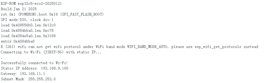
This example demonstrates how to connect to a WiFi network using the ESP32-C5-N16R4 development board with a statically assigned IP address.
Code
07_WIFI_StaticIP.ino
/**
 ******************************************************************************
 * @file     WiFi_StaticIP.ino
 * @brief    ESP32 connect to Wi-Fi with static IP configuration
 * @version V1.2
 * @date    2025-10-14
 * @author  liangjingheng
 * @company  Waveshare
 * @license MIT
 ******************************************************************************
 * Features:
 * 1. Connect ESP32 to "JSBZY-5G" Wi-Fi network with static IP
 * 2. Configure static IP, gateway, subnet mask, and DNS matching network settings
 * 3. Print connection status and network info via serial monitor
 * 4. Auto-reconnect if Wi-Fi connection drops
 ******************************************************************************
 */

#include <WiFi.h>

// Wi-Fi credentials (match network in screenshot)
const char *ssid = "waveshare";           // your Wi-Fi SSID
const char *password = "12345678";        // your Wi-Fi password

// Static IP configuration (matched to screenshot's network parameters)
IPAddress local_ip(192, 168, 9, 100);   // Static IP for ESP32
IPAddress gateway(192, 168, 11, 1);    // Gateway IP
IPAddress subnet(255, 255, 252, 0);    // Subnet mask
IPAddress dns(192, 168, 11, 1);        // DNS server

void setup() {
  // Initialize serial communication (115200 baud rate)
  Serial.begin(115200);
  while (!Serial){
    ; // Wait for serial port to initialize (for boards like Leonardo)
  }

  // Set Wi-Fi mode to Station (client mode)
  WiFi.mode(WIFI_STA);

  // Apply static IP configuration
  WiFi.config(local_ip, gateway, subnet, dns);

  // Start Wi-Fi connection
  WiFi.begin(ssid, password);
  Serial.println("Connecting to Wi-Fi (JSBZY-5G) with static IP...");

  // Wait for connection with retry logic
  int retryCount = 0;
  const int maxRetries = 15; // Retry for 15 seconds (15 * 1000ms)
  while (WiFi.status() != WL_CONNECTED && retryCount < maxRetries) {
    delay(1000);
    Serial.print(".");
    retryCount++;
  }

  // Print connection result
  if (WiFi.status() == WL_CONNECTED) {
    Serial.println("\nSuccessfully connected to Wi-Fi!");
    Serial.print("Static IP Address: ");
    Serial.println(WiFi.localIP());
    Serial.print("Gateway: ");
    Serial.println(gateway);
    Serial.print("Subnet Mask: ");
    Serial.println(subnet);
  }else{
    Serial.println("\nFailed to connect to Wi-Fi!");
    Serial.print("WiFi Status Code: ");
    Serial.println(WiFi.status()); // Print code for debugging (e.g., 6 = AUTH_FAIL)
  }
}

void loop() {
  // Periodically check Wi-Fi connection and auto-reconnect
  if (WiFi.status() != WL_CONNECTED) {
    Serial.println("Wi-Fi disconnected, attempting reconnection...");
    WiFi.begin(ssid, password); // Re-initiate connection
    int retry = 0;
    while (WiFi.status() != WL_CONNECTED && retry < 5) {
      delay(1000);
      Serial.print(".");
      retry++;
    }
    if (WiFi.status() == WL_CONNECTED) {
      Serial.println("\nReconnected to Wi-Fi!");
      Serial.print("Current IP: ");
      Serial.println(WiFi.localIP());
    }
  }
  delay(5000); // Check connection every 5 seconds
}
Code Analysis
- WIFI Network Configuration:
- You need to modify the WiFi name and password in the code to match those of your environment's WiFi router. If unavailable, you can create a mobile hotspot with the same name for the development board to connect and test.
- Properly configure the network IP-related settings.
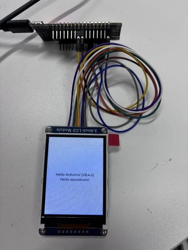
08_lvgl8.4.0_demo
This example demonstrates text display effects using lvgl_v8.4.0 along with GFX_Library_for_Arduino (GFX graphics library) and SensorLib (sensor library).
 |  |
|---|
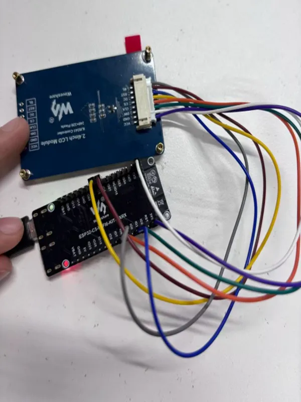
Hardware Connection
| 2.4inch LCD Module | ESP32-C5-N16R4 |
|---|---|
| VCC | 3V3 |
| GND | GND |
| DIN | GPIO2 |
| CLK | GPIO1 |
| CS | GPIO5 |
| D/C | GPIO3 |
| RST | GPIO4 |
| BL | GPIO6 |
Code
08_lvgl8.4.0_demo.ino
/*
 * @file    LVGL8.4.0_demo.ino
 * @brief   ESP32-C5 drives 2.4inch ILI9341 display and shows text labels via LVGL
 * @version V1.0
 * @date    2025-10-14
 * @author  liangjingheng
 * @company Waveshare
 * @license MIT
 ********************************************************************************/

/*Using LVGL with Arduino requires some extra steps:
 *Be sure to read the docs here: https://lvgl.io/docs/open/integration/frameworks/arduino  */

/*To use the built-in examples and demos of LVGL uncomment the includes below respectively.
 *You also need to copy `lvgl/examples` to `lvgl/src/examples`. Similarly for the demos `lvgl/demos` to `lvgl/src/demos`.
 Note that the `lv_examples` library is for LVGL v7 and you shouldn't install it for this version (since LVGL v8)
 as the examples and demos are now part of the main LVGL library. */

// #include <examples/lv_examples.h>
// #include <demos/lv_demos.h>

// #define DIRECT_MODE // Uncomment to enable full frame buffer

#include <lvgl.h>
#include <Arduino_GFX_Library.h>

#define LCD_SCK 1
#define LCD_DIN 2
#define LCD_CS 5
#define LCD_DC 3
#define LCD_RST 4
#define LCD_BL 6

#define GFX_BL LCD_BL

Arduino_DataBus *bus = new Arduino_HWSPI(LCD_DC, LCD_CS, LCD_SCK, LCD_DIN);
Arduino_GFX *gfx = new Arduino_ILI9341(
  bus, LCD_RST, 0 /* rotation */, false /* IPS */
);

uint32_t screenWidth;
uint32_t screenHeight;
uint32_t bufSize;
lv_disp_draw_buf_t draw_buf;
lv_color_t *disp_draw_buf1;
lv_color_t *disp_draw_buf2;
lv_disp_drv_t disp_drv;

/* Display flushing */
void my_disp_flush(lv_disp_drv_t *disp_drv, const lv_area_t *area, lv_color_t *color_p) {
  uint32_t w = (area->x2 - area->x1 + 1);
  uint32_t h = (area->y2 - area->y1 + 1);

#if (LV_COLOR_16_SWAP != 0)
  gfx->draw16bitBeRGBBitmap(area->x1, area->y1, (uint16_t *)&color_p->full, w, h);
#else
  gfx->draw16bitRGBBitmap(area->x1, area->y1, (uint16_t *)&color_p->full, w, h);
#endif

  lv_disp_flush_ready(disp_drv);
}

void setup() {

  Serial.begin(115200);
  Serial.println("Arduino_GFX Hello World example");

  // Init Display
  if (!gfx->begin()) {
    Serial.println("gfx->begin() failed!");
  }

  gfx->fillScreen(RGB565_BLACK);

#ifdef GFX_BL
  pinMode(GFX_BL, OUTPUT);
  digitalWrite(GFX_BL, HIGH);
#endif

  lv_init();

  screenWidth = gfx->width();
  screenHeight = gfx->height();

  bufSize = screenWidth * 120;

  disp_draw_buf1 = (lv_color_t *)heap_caps_malloc(bufSize * 2, MALLOC_CAP_DEFAULT | MALLOC_CAP_8BIT);

  disp_draw_buf2 = (lv_color_t *)heap_caps_malloc(bufSize * 2, MALLOC_CAP_DEFAULT | MALLOC_CAP_8BIT);

  lv_disp_draw_buf_init(&draw_buf, disp_draw_buf1, disp_draw_buf2, bufSize);

  /*Initialize the display*/
  lv_disp_drv_init(&disp_drv);
  /*Change the following line to your display resolution*/
  disp_drv.hor_res = screenWidth;
  disp_drv.ver_res = screenHeight;
  disp_drv.flush_cb = my_disp_flush;
  disp_drv.draw_buf = &draw_buf;

  lv_disp_drv_register(&disp_drv);

  /*Initialize the (dummy) input device driver*/
  lv_obj_t *label = lv_label_create(lv_scr_act());
  lv_label_set_text(label, "Hello Arduino! (V" GFX_STR(LVGL_VERSION_MAJOR) "." GFX_STR(LVGL_VERSION_MINOR) "." GFX_STR(LVGL_VERSION_PATCH) ")");
  lv_obj_align(label, LV_ALIGN_CENTER, 0, 0);
  /*hello waveshare label*/
  lv_obj_t *label_waveshare = lv_label_create(lv_scr_act());
  lv_label_set_text(label_waveshare, "Hello waveshare!");
  lv_obj_align(label_waveshare, LV_ALIGN_CENTER, 0, 20);

  /* Option 3: Or try out a demo. Don't forget to enable the demos in lv_conf.h. E.g. LV_USE_DEMOS_WIDGETS*/
  // lv_demo_widgets();
  // lv_demo_benchmark();
  // lv_demo_music();

  Serial.println("Setup done");
}

void loop() {
  lv_timer_handler(); /* let the GUI do its work */
  delay(1);
}
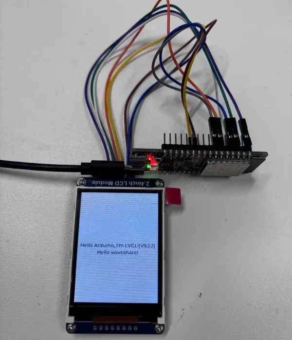
09_lvgl9.2.2_demo
This example demonstrates text display effects using lvgl_v9.2.2 along with GFX_Library_for_Arduino (GFX graphics library) and SensorLib (sensor library).
 |  |
|---|
Hardware Connection
| 2.4inch LCD Module | ESP32-C5-N16R4 |
|---|---|
| VCC | 3V3 |
| GND | GND |
| DIN | GPIO2 |
| CLK | GPIO1 |
| CS | GPIO5 |
| D/C | GPIO3 |
| RST | GPIO4 |
| BL | GPIO6 |
Code
09_lvgl9.2.2_demo.ino
/*
 * @file    LVGL9.2.2_demo.ino
 * @brief   ESP32-C5 drives 2.4inch ILI9341 display and shows text labels via LVGL
 * @version V1.0
 * @date    2025-10-14
 * @author  liangjingheng
 * @company Waveshare
 * @license MIT
 ********************************************************************************/
/*Using LVGL with Arduino requires some extra steps:
 *Be sure to read the docs here: https://lvgl.io/docs/open/integration/frameworks/arduino  */

/*To use the built-in examples and demos of LVGL uncomment the includes below respectively.
 *You also need to copy `lvgl/examples` to `lvgl/src/examples`. Similarly for the demos `lvgl/demos` to `lvgl/src/demos`.
 *Note that the `lv_examples` library is for LVGL v7 and you shouldn't install it for this version (since LVGL v8)
 *as the examples and demos are now part of the main LVGL library. */

// #include <examples/lv_examples.h>
// #include <demos/lv_demos.h>

// #define DIRECT_RENDER_MODE // Uncomment to enable full frame buffer
#include <lvgl.h>
#include <Arduino_GFX_Library.h>

#define LCD_SCK 1
#define LCD_DIN 2
#define LCD_CS 5
#define LCD_DC 3
#define LCD_RST 4
#define LCD_BL 6

#define GFX_BL LCD_BL

Arduino_DataBus *bus = new Arduino_HWSPI(LCD_DC, LCD_CS, LCD_SCK, LCD_DIN);
Arduino_GFX *gfx = new Arduino_ILI9341(
  bus, LCD_RST, 0 /* rotation */, false /* IPS */
);

uint32_t screenWidth;
uint32_t screenHeight;
uint32_t bufSize;
lv_display_t *disp;
lv_color_t *disp_draw_buf;

#if LV_USE_LOG != 0
void my_print(lv_log_level_t level, const char *buf)
{
  LV_UNUSED(level);
  Serial.println(buf);
  Serial.flush();
}
#endif

uint32_t millis_cb(void)
{
  return millis();
}

/* LVGL calls it when a rendered image needs to copied to the display*/
void my_disp_flush(lv_display_t *disp, const lv_area_t *area, uint8_t *px_map)
{
#ifndef DIRECT_RENDER_MODE
  uint32_t w = lv_area_get_width(area);
  uint32_t h = lv_area_get_height(area);

  gfx->draw16bitRGBBitmap(area->x1, area->y1, (uint16_t *)px_map, w, h);
#endif // #ifndef DIRECT_RENDER_MODE

  /*Call it to tell LVGL you are ready*/
  lv_disp_flush_ready(disp);
}

void setup()
{
#ifdef DEV_DEVICE_INIT
  DEV_DEVICE_INIT();
#endif

  Serial.begin(115200);
  // Serial.setDebugOutput(true);
  // while(!Serial);
  Serial.println("Arduino_GFX LVGL_Arduino_v9 example ");
  String LVGL_Arduino = String('V') + lv_version_major() + "." + lv_version_minor() + "." + lv_version_patch();
  Serial.println(LVGL_Arduino);

  // Init Display
  if (!gfx->begin())
  {
    Serial.println("gfx->begin() failed!");
  }
  gfx->fillScreen(RGB565_BLACK);

#ifdef GFX_BL
  pinMode(GFX_BL, OUTPUT);
  digitalWrite(GFX_BL, HIGH);
#endif

  lv_init();

  /*Set a tick source so that LVGL will know how much time elapsed. */
  lv_tick_set_cb(millis_cb);

  /* register print function for debugging */
#if LV_USE_LOG != 0
  lv_log_register_print_cb(my_print);
#endif

  screenWidth = gfx->width();
  screenHeight = gfx->height();

#ifdef DIRECT_RENDER_MODE
  bufSize = screenWidth * screenHeight;
#else
  bufSize = screenWidth * 120;
#endif

  disp_draw_buf = (lv_color_t *)heap_caps_malloc(bufSize * 2, MALLOC_CAP_INTERNAL | MALLOC_CAP_8BIT);
  if (!disp_draw_buf)
  {
    // remove MALLOC_CAP_INTERNAL flag try again
    disp_draw_buf = (lv_color_t *)heap_caps_malloc(bufSize * 2, MALLOC_CAP_8BIT);
  }

  if (!disp_draw_buf)
  {
    Serial.println("LVGL disp_draw_buf allocate failed!");
  }
  else
  {
    disp = lv_display_create(screenWidth, screenHeight);
    lv_display_set_flush_cb(disp, my_disp_flush);
#ifdef DIRECT_RENDER_MODE
    lv_display_set_buffers(disp, disp_draw_buf, NULL, bufSize * 2, LV_DISPLAY_RENDER_MODE_DIRECT);
#else
    lv_display_set_buffers(disp, disp_draw_buf, NULL, bufSize * 2, LV_DISPLAY_RENDER_MODE_PARTIAL);
#endif

    /*Initialize the (dummy) input device driver*/
    // lv_indev_t *indev = lv_indev_create();
    // lv_indev_set_type(indev, LV_INDEV_TYPE_POINTER); /*Touchpad should have POINTER type*/
    // lv_indev_set_read_cb(indev, my_touchpad_read);

    /* Option 1: Create a simple label
     * ---------------------
     */
    lv_obj_t *label = lv_label_create(lv_scr_act());
    lv_label_set_text(label, "Hello Arduino, I'm LVGL!(V" GFX_STR(LVGL_VERSION_MAJOR) "." GFX_STR(LVGL_VERSION_MINOR) "." GFX_STR(LVGL_VERSION_PATCH) ")");
    lv_obj_align(label, LV_ALIGN_CENTER, 0, 0);

    /*hello waveshare label*/
    lv_obj_t *label_waveshare = lv_label_create(lv_scr_act());
    lv_label_set_text(label_waveshare, "Hello waveshare!");
    lv_obj_align(label_waveshare, LV_ALIGN_CENTER, 0, 20);

    /* Option 2: Try an example. See all the examples
     *  - Online: https://docs.lvgl.io/master/examples.html
     *  - Source codes: https://github.com/lvgl/lvgl/tree/master/examples
     * ----------------------------------------------------------------
     */
    // lv_example_btn_1();

    /* Option 3: Or try out a demo. Don't forget to enable the demos in lv_conf.h. E.g. LV_USE_DEMOS_WIDGETS
     * -------------------------------------------------------------------------------------------
     */
    // lv_demo_widgets();
    // lv_demo_benchmark();
    // lv_demo_music();
  }

  Serial.println("Setup done");
}

void loop()
{
  lv_task_handler(); /* let the GUI do its work */
  delay(5);
}
Code Analysis
setup()function:- Initializes basic device and serial port.
- Initializes and controls the display.
- Configure LVGL core and buffer.
- UI elements and extended functionality.