Working with ESP-IDF
This chapter includes the following sections, please read as needed:
ESP-IDF Getting Started
New to ESP32 ESP-IDF development and looking to get started quickly? We have prepared a general Getting Started Tutorial for you.
- Section 1: Environment Setup
- Section 2: Running Examples
- Section 3: Creating a Project
- Section 4: Using Components
- Section 5: Debugging
- Section 6: FreeRTOS
- Section 7: Peripherals
- Section 8: Wi-Fi Programming
- Section 9: BLE Programming
Please Note: This tutorial uses the ESP32-S3-Zero as a teaching example, and all hardware code is based on its pinout. Before you start, it is recommended that you check the pinout of your development board to ensure the pin configuration is correct.
Setting Up Development Environment
The following guide uses Windows as an example, demonstrating development using VS Code + the ESP-IDF extension. macOS and Linux users should refer to the official documentation.
The screenshots in this section use ESP-IDF V5.5.2 as an example. When installing, please select the ESP-IDF version that matches your board's example.
Install the ESP-IDF Development Environment
-
Download the installation manager from the ESP-IDF Installation Manager page. This is Espressif's latest cross-platform installer. The following steps demonstrate how to use its offline installation feature.
Click the Offline Installer tab on the page, then select Windows as the operating system and the ESP-IDF version you need (the version shown in the screenshot is for reference only — choose the version that fits your actual needs).

After confirming your selection, click the download button. The browser will automatically download two files: the ESP-IDF Offline Package (.zst) and the ESP-IDF Installer (.exe).

Please wait for both files to finish downloading.
-
Once the download is complete, double-click to run the ESP-IDF Installer (eim-gui-windows-x64.exe).
The installer will automatically detect if the offline package exists in the same directory. Click Install from archive.

Next, select the installation path. We recommend using the default path. If you need to customize it, ensure the path does not contain Chinese characters or spaces. Click Start installation to proceed.

-
When you see the following screen, the ESP-IDF installation is successful.

-
We recommend installing the drivers as well. Click Finish installation, then select Install driver.

Install Visual Studio Code and the ESP-IDF Extension
-
Download and install Visual Studio Code.
-
During installation, it is recommended to check Add "Open with Code" action to Windows Explorer file context menu to facilitate opening project folders quickly.
-
In VS Code, click the Extensions icon
 in the Activity Bar on the side (or use the shortcut Ctrl + Shift + X) to open the Extensions view.
 -
Enter ESP-IDF in the search box, locate the ESP-IDF extension, and click Install.

-
For ESP-IDF extension versions ≥ 2.0, the extension will automatically detect and recognize the ESP-IDF environment installed in the previous steps, requiring no manual configuration.
Example
The ESP-IDF examples are located in the ESP-IDF directory of the example package.
| Example | Basic Description |
|---|---|
| 01_GPIO | Control the logic level of the exposed GPIO pins |
| 02_BlinkRGB | Implement a breathing LED effect on the RGB LED |
| 03_GetchipID | Obtain and print hardware information of the ESP32-C5-Zero chip, including model, revision, core count, and chip ID |
| 04_BLE | Use the ESP32-C5-Zero development board to connect to BLE beacons and receive broadcast data |
| 05_UART | Implement UART communication using the ESP32-C5-Zero development board |
| 06_WIFI_AP | Configure the ESP32-C5-Zero development board as an AP hotspot (2.4G), allowing other Wi-Fi devices to connect |
| 07_WIFI_STA | Connect to a specified Wi-Fi network and print connection information |
| 08_WIFI_StaticIP | Use the ESP32-C5-Zero development board to connect to Wi-Fi with a static IP address |
| 09_ZIGBEE | Use Zigbee on the ESP32-C5-Zero development board to control the onboard LED on/off |
| 10_Mem_Security | Demonstrate memory security features on the ESP32-C5-Zero development board |
01_GPIO
Code
01_GPIO.ino
void app_main(void)
{
    // Configure all selected GPIOs as push-pull outputs
    gpio_config_t io_conf = {
        .intr_type = GPIO_INTR_DISABLE,
        .mode = GPIO_MODE_OUTPUT,
        .pin_bit_mask = GPIO_OUTPUT_PIN_SEL,
        .pull_down_en = 0,
        .pull_up_en = 0,
    };
    ESP_ERROR_CHECK(gpio_config(&io_conf));

    int output_level = 0;
    size_t gpio_count = sizeof(gpio_pins) / sizeof(gpio_pins[0]);

    ESP_LOGI(log_tag, "Initialization done. Start toggling GPIO pins synchronously...");

    while (true) {
        // Set all selected pins to the same level
        for (size_t i = 0; i < gpio_count; i++) {
            ESP_ERROR_CHECK(gpio_set_level(gpio_pins[i], output_level));
        }

        // Flip output level for next cycle
        output_level = !output_level;
        vTaskDelay(pdMS_TO_TICKS(500));
    }
}
Code Analysis
- The code first iterates through selected GPIO pins, setting them to the same output level, then toggles the level synchronously using
output_level = !output_level. vTaskDelay(pdMS_TO_TICKS(500))controls the blink period for easy observation of GPIO output changes.
02_BlinkRGB
Code
02_BlinkRGB.ino
    while (true) {
        // Calculate current color
        led_strip_set_wheel(led_strip, wheel_pos);

        // Refresh LED
        led_strip_refresh(led_strip);

        // Increment position (uint8_t automatically wraps to 0 after 255)
        wheel_pos++;

        vTaskDelay(pdMS_TO_TICKS(20));
    }
Code Analysis
led_strip_set_wheel()computes the current color based onwheel_pos, ideal for creating a rainbow cycle effect.- A 20 ms delay after each
led_strip_refresh()makes the color transitions appear smoother.
Operation Result
 |  |  |
|---|
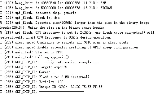
03_GetchipID
Code
03_GetchipID.ino
void app_main(void)
{
    ESP_LOGI(log_tag, "--- Chip information example ---");

    /* Get chip information */
    esp_chip_info_t chip_info;
    esp_chip_info(&chip_info);

    /* Print target and core count */
    ESP_LOGI(log_tag, "Target: %s", CONFIG_IDF_TARGET);
    ESP_LOGI(log_tag, "Cores: %d", chip_info.cores);

    /* Get and print flash size */
    uint32_t flash_size;
    esp_flash_get_size(NULL, &flash_size);
    ESP_LOGI(log_tag, "Flash size: %" PRIu32 " MB (%s)",
           flash_size / (1024 * 1024),
           (chip_info.features & CHIP_FEATURE_EMB_FLASH) ? "embedded" : "external");

    /* Print revision */
    ESP_LOGI(log_tag, "Revision: %d", chip_info.revision);

    /* Use default MAC address as a unique ID */
    uint8_t mac[6];
    esp_efuse_mac_get_default(mac);
    ESP_LOGI(log_tag, "Unique ID (MAC): %02X:%02X:%02X:%02X:%02X:%02X",
           mac[0], mac[1], mac[2], mac[3], mac[4], mac[5]);

    ESP_LOGI(log_tag, "------------------------");

    /* Run forever */
    while (true) {
        vTaskDelay(pdMS_TO_TICKS(5000));
    }
}
Code Analysis
esp_chip_info()reads basic hardware information such as core count and chip revision.esp_efuse_mac_get_default()retrieves the default MAC address, which can be used as a unique device identifier.
Operation Result
 |
|---|
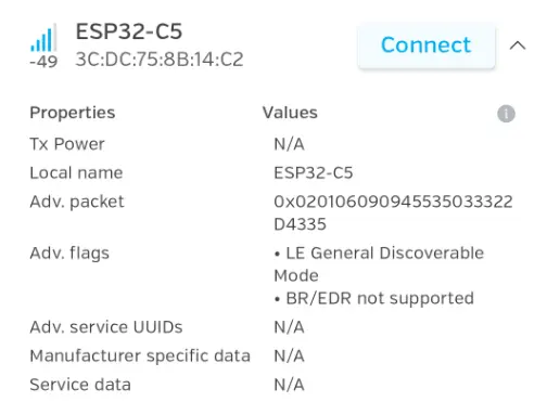
04_BLE
Code
04_BLE.ino
void app_main(void) {
    // 1. Initialize NVS (required for Bluetooth stack)
    if (nvs_flash_init() != ESP_OK) {
        nvs_flash_erase();
        nvs_flash_init();
    }

    // 2. Initialize Bluetooth Controller
    esp_bt_controller_config_t bt_cfg = BT_CONTROLLER_INIT_CONFIG_DEFAULT();
    esp_bt_controller_init(&bt_cfg);
    esp_bt_controller_enable(ESP_BT_MODE_BLE);

    // 3. Initialize Bluedroid Stack
    esp_bluedroid_init();
    esp_bluedroid_enable();

    // 4. Register GAP callback and configure advertising data
    esp_ble_gap_register_callback(gap_event_handler);
    esp_ble_gap_config_adv_data_raw(adv_data, sizeof(adv_data));

    ESP_LOGI(TAG, "BLE stack initialized, setting up advertising...");
}
Code Analysis
- The code first initializes NVS, the Bluetooth controller, and the Bluedroid stack – all prerequisites for BLE advertising.
esp_ble_gap_config_adv_data_raw()configures raw advertising data, after which the device becomes discoverable by external scanners.
Operation Result
 |
|---|
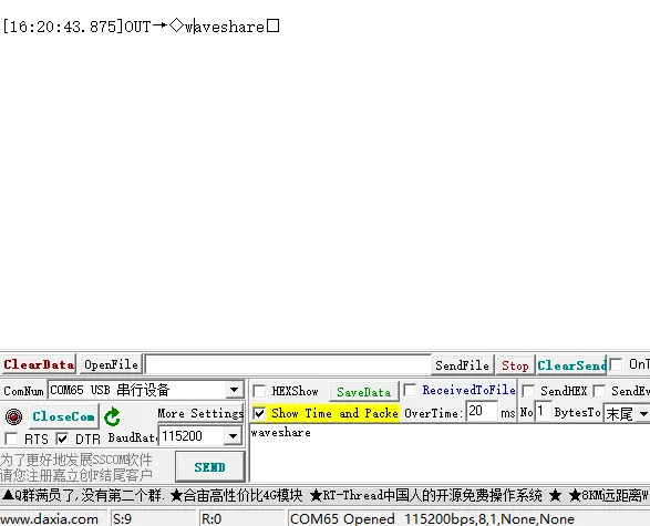
05_UART
Code
05_UART.ino
void app_main(void) {
    uart_config_t uart_cfg = {
        .baud_rate = 115200,
        .data_bits = UART_DATA_8_BITS,
        .parity    = UART_PARITY_DISABLE,
        .stop_bits = UART_STOP_BITS_1,
        .flow_ctrl = UART_HW_FLOWCTRL_DISABLE,
        .source_clk = UART_SCLK_DEFAULT,
    };

    ESP_ERROR_CHECK(uart_param_config(UART_PORT, &uart_cfg));

    ESP_ERROR_CHECK(uart_driver_install(UART_PORT, BUF_SIZE * 2, BUF_SIZE * 2, 0, NULL, 0));

    ESP_ERROR_CHECK(uart_set_pin(UART_PORT, TXD_PIN, RXD_PIN, UART_PIN_NO_CHANGE, UART_PIN_NO_CHANGE));

    xTaskCreate(rx_task, "uart_rx", 4096, NULL, 10, NULL);
    xTaskCreate(tx_task, "uart_tx", 4096, NULL, 9, NULL);
}
Code Analysis
uart_param_config(),uart_driver_install()anduart_set_pin()configure the UART parameters, driver, and pin mapping respectively.- Finally,
xTaskCreate()starts separate receive and transmit tasks, allowing UART reception and transmission to run concurrently.
Operation Result
 |
|---|
06_WIFI_AP
Code
06_WIFI_AP.ino
void app_main(void) {
    // 1. Initialize NVS (required for AP mode as well).
    if (nvs_flash_init() != ESP_OK) {
        nvs_flash_erase();
        nvs_flash_init();
    }

    // 2. Initialize network stack and create the default AP netif.
    esp_netif_init();
    esp_event_loop_create_default();
    esp_netif_create_default_wifi_ap();

    // 3. Initialize WiFi driver and register event handler.
    wifi_init_config_t cfg = WIFI_INIT_CONFIG_DEFAULT();
    esp_wifi_init(&cfg);
    esp_event_handler_instance_register(WIFI_EVENT, ESP_EVENT_ANY_ID, &wifi_handler, NULL, NULL);

    // 4. Configure AP parameters with designated initializer.
    wifi_config_t ap_cfg = {
        .ap = {
            .ssid = SSID,
            .password = PWD,
            .ssid_len = 0,             // Use null-terminated SSID string length.
            .channel = 1,
            .max_connection = 4,
            .authmode = WIFI_AUTH_WPA2_PSK
        },
    };

    // Switch to open mode when password is empty.
    if (PWD[0] == '\0') ap_cfg.ap.authmode = WIFI_AUTH_OPEN;

    esp_wifi_set_mode(WIFI_MODE_AP);
    esp_wifi_set_config(WIFI_IF_AP, &ap_cfg);
    esp_wifi_start();

    ESP_LOGI(TAG, "AP Mode started. SSID: %s", SSID);
}
Code Analysis
- This code configures the board as an AP (Access Point) using
esp_wifi_set_mode(WIFI_MODE_AP)andesp_wifi_set_config(). - If the password is empty, it automatically switches to open-mode hotspot for quick connection testing.
Operation Result
 |
|---|
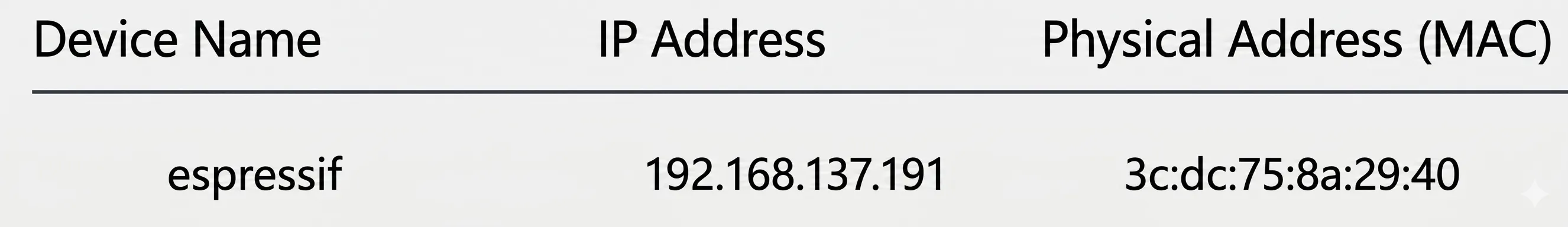
07_WIFI_STA
Code
07_WIFI_STA.ino
void app_main(void) {
  // 1. Initialize NVS (WiFi configuration needs to be stored in NVS)
  if (nvs_flash_init() != ESP_OK) {
    nvs_flash_erase();
    nvs_flash_init();
  }

  // 2. Initialize network stack and underlying drivers
  esp_netif_init();
  esp_event_loop_create_default();
  esp_netif_create_default_wifi_sta();

  wifi_init_config_t cfg = WIFI_INIT_CONFIG_DEFAULT();
  esp_wifi_init(&cfg);

  // 3. Register event handlers (handle all WiFi and IP related events)
  esp_event_handler_instance_register(WIFI_EVENT, ESP_EVENT_ANY_ID,
                                      &wifi_handler, NULL, NULL);
  esp_event_handler_instance_register(IP_EVENT, IP_EVENT_STA_GOT_IP,
                                      &wifi_handler, NULL, NULL);

  // 4. Initialize GPIO26 as output
  gpio_reset_pin(GPIO_NUM_26);
  gpio_set_direction(GPIO_NUM_26, GPIO_MODE_OUTPUT);

  GPIO26_ON();
  // 4. Configure and start WiFi
  wifi_config_t wifi_cfg = {
      .sta =
          {
              .ssid = SSID,
              .password = PWD,
          },
  };
  esp_wifi_set_mode(WIFI_MODE_STA);
  esp_wifi_set_config(WIFI_IF_STA, &wifi_cfg);
  esp_wifi_start();

  ESP_LOGI(TAG, "WiFi station started.");
}
Code Analysis
esp_netif_create_default_wifi_sta()creates the default STA network interface for connecting to a router.- After registering Wi-Fi and IP event callbacks, the program can execute corresponding logic upon successful connection or disconnection.
Operation Result
 |
|---|
08_WIFI_StaticIP
Code
08_WIFI_StaticIP.ino
    esp_netif_ip_info_t ip_info = {
        .ip.addr = ipaddr_addr("192.168.1.77"),
        .gw.addr = ipaddr_addr("192.168.1.1"),
        .netmask.addr = ipaddr_addr("255.255.255.0")
    };
Code Analysis
- The
esp_netif_ip_info_tstructure is used to set a static IP address, gateway, and subnet mask in one go. - This approach is suitable for scenarios where a fixed device address is required, making it easy to access the board via a known IP address on the local network.
Operation Result
09_ZIGBEE
-
- Prepare two ESP32-C5-Zero development boards, ensuring they are powered correctly and ready for program flashing.
-
- Connect the first development board to the computer. Use the flashing tool to flash the HA_on_off_light program onto this board (this program controls the RGB LED). After flashing, keep the board powered on.
-
- Connect the second development board to the computer. Use the flashing tool to flash the HA_on_off_switch program onto this board (this program implements the control function via the BOOT button). After flashing, keep the board powered on.
Code
09_ZIGBEE.ino
void app_main(void)
{
    esp_zb_platform_config_t config = {
        .radio_config = ESP_ZB_DEFAULT_RADIO_CONFIG(),
        .host_config = ESP_ZB_DEFAULT_HOST_CONFIG(),
    };
    ESP_ERROR_CHECK(nvs_flash_init());
    ESP_ERROR_CHECK(esp_zb_platform_config(&config));

    xTaskCreate(esp_zb_task, "Zigbee_main", 4096, NULL, 5, NULL);
}
Code Analysis
esp_zb_platform_config()initializes the Zigbee platform layer, preparing the radio and host configuration.xTaskCreate(esp_zb_task, ...)runs the Zigbee main task independently, facilitating network control logic expansion.
Operation Result
10_Mem_Security
Code
10_Mem_Security.ino
    print_status();
    print_privilege();
    test_hw_crypto();
    test_tee_apm();
Code Analysis
- These lines display the current security status, privilege information, and test hardware cryptography as well as TEE/APM related functions.
- Useful for quickly verifying whether the chip's security features are initialized correctly.