Working with Arduino
This chapter includes the following sections, please read as needed:
Before running the examples, please ensure the following conditions are met:
- ESP32-C6-LCD-2.73 development board is ready.
- The board is connected to the PC via a USB data cable.
- Arduino IDE is installed.
- ESP32 Arduino Core supporting ESP32-C6 is installed.
- The product's example program package has been downloaded.
- To run
01_lvgl_demoor07_example, please install thelibraries/lvglincluded in the example package. - To run
04_I2C_pcf85063or07_example, please installSensorLib, which providesSensorPCF85063.hpp.
Arduino Getting Started
New to Arduino ESP32 development and looking for a quick start? We have prepared a comprehensive Getting Started Tutorial for you.
- Section 0: Getting to Know ESP32
- Section 1: Installing and Configuring Arduino IDE
- Section 2: Arduino Basics
- Section 3: Digital Output/Input
- Section 4: Analog Input
- Section 5: Pulse Width Modulation (PWM)
- Section 6: Serial Communication (UART)
- Section 7: I2C Communication
- Section 8: SPI Communication
- Section 9: Wi-Fi Basics
- Section 10: Web Server
- Section 11: Bluetooth
- Section 12: LVGL GUI Development
- Section 13: Comprehensive Project
Note: This tutorial uses the ESP32-S3-Zero as a reference example, and all hardware code is based on its pinout. Before you start, we recommend checking the pinout of your development board to ensure the pin configuration is correct.
Setting Up the Development Environment
1. Installing and Configuring the Arduino IDE
Please refer to the tutorial Installing and Configuring the Arduino IDE to download and install the Arduino IDE.
2. Installing the ESP32 Board Support Package
Install the esp32 by Espressif Systems board support package in the Arduino IDE Board Manager.
The onboard MCU module of ESP32-C6-LCD-2.73 is ESP32-C6-WROOM-1-N16. Please install the esp32 by Espressif Systems board support package that supports ESP32-C6.
If an older version of ESP32 Arduino Core is used, the board may not be correctly recognized, leading to serial download failures or inability to flash the program.
ESP32-C6-LCD-2.73 Board Installation Requirements:
| Board Name | Board Installation Requirement | Version Requirement |
|---|---|---|
| ESP32 by Espressif Systems | "Offline" / "Online" installation | Refer to the current example package instructions |
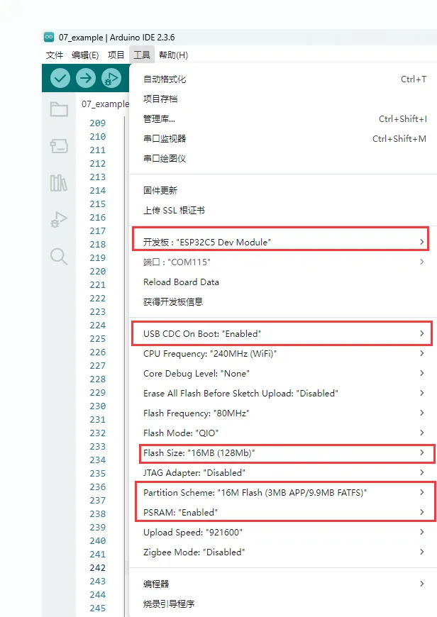
After installation, select the appropriate ESP32-C6 board in Arduino IDE and select the USB serial port currently connected.
In the ESP32-C6-LCD-2.73 Arduino project settings, the board must be selected as ESP32C6 Dev Module.
3. Installing Libraries and Example Dependencies
The Arduino examples for this product primarily utilize the built-in capabilities of Arduino ESP32 Core, the source code provided in the example directories, and the library files included in the resource package.
| Library or File | Purpose | Recommended Version / Source | Examples | Installation Method |
|---|---|---|---|---|
| Arduino ESP32 Core | ESP32-C6 board support, flashing, and basic peripheral interfaces | Refer to current example package | All examples | Arduino IDE Board Manager |
lvgl | LVGL GUI framework | libraries/lvgl in example package, LVGL v8.4.0 | 01_lvgl_demo, 07_example | Offline manual copy to Arduino libraries directory |
SensorLib / SensorPCF85063.hpp | PCF85063 RTC driver | SensorLib | 04_I2C_pcf85063, 07_example | Arduino Library Manager or offline libraries directory |
01_lvgl_demo and 07_example are based on LVGL v8.4.0. Please do not replace them with LVGL v9, as interfaces such as lv_disp_drv_t, lv_disp_draw_buf_t, and lv_disp_drv_register() will be incompatible.
Offline / Manual Installation:
-
Download and extract the product example program package.
-
Locate the LVGL library directory in the example package:
code/arduino/libraries/lvgl -
Copy the entire lvgl folder to the Arduino libraries directory.
The default libraries directory on Windows is usually:
C:\Users\<username>\Documents\Arduino\librariesYou can also check the
Sketchbook locationviaFile > Preferencesin the Arduino IDE; thelibrariesfolder under that path is the libraries directory. -
Restart Arduino IDE after installation, then open the examples to compile.
Installation Verification:
- The
lvgldirectory is visible underDocuments\Arduino\libraries. Documents\Arduino\libraries\lvgl\library.propertiesshowsversion=8.4.0.- The
lv_conf.hfile in the01_lvgl_demoand07_exampledirectories must remain within their respective example directories. Do not move it to the global Arduino libraries directory or delete it. - Do not keep multiple versions of
lvglsimultaneously to avoid header file conflicts. - If compiling
04_I2C_pcf85063or07_exampleresults in an error indicatingSensorPCF85063.hppis missing, please verify thatSensorLibis installed.
4. Arduino Project Settings
- Open Arduino IDE.
- Install the
esp32 by Espressif Systemsboard support package that supports ESP32-C6. - In
Tools>Board, selectESP32C6 Dev Module. - Select the USB serial port currently connected.
- Open the corresponding
.inofile undercode/arduino/examplesfor compilation and flashing.
When using arduino-cli, refer to the following commands:
arduino-cli core install esp32:esp32
arduino-cli compile --fqbn esp32:esp32:esp32c6 code/arduino/examples/01_lvgl_demo
Example
The Arduino examples are located in the code/arduino/examples directory of the example package. Each example has been adapted to the onboard hardware connections of the ESP32-C6-LCD-2.73.
1. Onboard Resources
| Feature | Device or Interface | Pins or Notes |
|---|---|---|
| LCD | ILI9488, SPI, 320 x 320 | SCLK GPIO0, MOSI GPIO1, MISO GPIO18, DC GPIO19, CS GPIO8 |
| LCD Reset | CH32V003 I/O Expander | IO0 |
| LCD Backlight | CH32V003 PWM | PWM Register 0x05 |
| I/O Expander | CH32V003, I2C address 0x24 | SDA GPIO20, SCL GPIO2 |
| 6‑axis IMU | QMI8658, I2C address 0x6B | SDA GPIO20, SCL GPIO2 |
| RTC | PCF85063, I2C address 0x51 | SDA GPIO20, SCL GPIO2 |
| Temp/Humidity Sensor | SHTC3, I2C address 0x70 | SDA GPIO20, SCL GPIO2 |
| TF | SDSPI | SCLK GPIO0, MOSI GPIO1, MISO GPIO18, CS GPIO10 |
| BOOT Button | User Button | GPIO9 |
Display, backlight, reset, TF card, and sensor pins have been adapted according to the product's hardware connections in the examples. For general secondary development, it is recommended to prioritize modifications to the application layer and UI logic. Only modify the underlying pin definitions when changing hardware connections or porting to other boards.
2. Example List
| Example Directory | Basic Description | Main Test Content |
|---|---|---|
| 01_lvgl_demo | Runs the LVGL stress test interface based on ILI9488 and LVGL v8.4.0 | LCD, Backlight, LVGL |
| 02_SD_Card | Mounts TF card via SDSPI and performs file write and read-back checks | TF, SDSPI, File I/O |
| 03_I2C_qmi8658 | Reads QMI8658 6‑axis sensor data and outputs accelerometer and gyroscope data over serial | IMU, I2C bus |
| 04_I2C_pcf85063 | Initializes the PCF85063 RTC, sets a test time, and periodically prints RTC time over serial | RTC, I2C bus |
| 05_shtc3 | Reads SHTC3 temperature and humidity sensor ID, temperature, and humidity, and outputs over serial | Temp/Humidity sensor, CRC check |
| 06_exio | Tests the onboard CH32V003 I/O expander, toggles IO4-IO14 output levels cyclically | I/O expansion, I2C bus |
| 07_example | Comprehensively displays RTC, SHTC3, QMI8658, and TF card status, with BOOT button for page switching | LCD, Backlight, Sensors, RTC, TF Card |
3. Directory Structure
The current Arduino examples directory contains the following projects:
code/arduino
|-- examples
|   |-- 01_lvgl_demo
|   |-- 02_SD_Card
|   |-- 03_I2C_qmi8658
|   |-- 04_I2C_pcf85063
|   |-- 05_shtc3
|   |-- 06_exio
|   `-- 07_example
`-- libraries
    `-- lvgl
Each subdirectory is an independent Arduino example. To open an example, open the .ino file inside that directory, for example:
code/arduino/examples/01_lvgl_demo/01_lvgl_demo.ino
libraries/lvgl is the LVGL v8.4.0 library file used by 01_lvgl_demo and 07_example. Before compiling these two examples, you need to copy lvgl to the Arduino libraries directory.
4. Recommended First‑Run Order
It is recommended to run the examples in the following order:
06_exio
  -> 05_shtc3
  -> 03_I2C_qmi8658
  -> 04_I2C_pcf85063
  -> 02_SD_Card
  -> 01_lvgl_demo
  -> 07_example
- First, use
06_exioto verify the CH32V003 IO expansion and I2C bus. Since LCD reset and backlight control are both related to CH32V003, it is recommended to confirm this example works properly first. - Then, use
05_shtc3,03_I2C_qmi8658, and04_I2C_pcf85063to verify the I2C peripherals. - Next, use
02_SD_Cardto verify the TF card and SDSPI. - Finally, run
01_lvgl_demoand07_exampleto verify the LCD, backlight, LVGL, and the comprehensive dashboard.
5. Usage Notes
- The Arduino example directory is
code/arduino/examples. Please do not mix it with the ESP-IDF example directory. - This product shares a single I2C bus:
SDA GPIO20,SCL GPIO2. CH32V003, QMI8658, PCF85063, and SHTC3 are all on this I2C bus. - Before running
02_SD_Cardand07_example, insert a TF card formatted as FAT or FAT32. 04_I2C_pcf85063writes a fixed test time on every power‑up by default. To enable continuous RTC time‑keeping, comment outi2c_rtc_setTime().01_lvgl_demoand07_exampleare already adapted for ILI9488 display. No additional GFX display library is required.- If copying code from other projects, please pay special attention to the LCD SPI pins, TF card chip select (CS) pin, and CH32V003 IO expansion configuration.
- For troubleshooting compilation, screen illumination, I2C addresses, etc., please refer to the FAQ.
6. Example Details
01_lvgl_demo
Function Description
This example is used to verify LCD display, backlight, and basic LVGL operation. The program initializes the ILI9488 LCD via SPI, uses CH32V003 to control LCD reset and backlight, and then starts the LVGL stress test interface.
Code Entry
01_lvgl_demo/01_lvgl_demo.ino
01_lvgl_demo/esp_lcd_ili9488.c
01_lvgl_demo/esp_lcd_ili9488.h
01_lvgl_demo/lv_conf.h
Recommended key code sections:
| Code | Purpose |
|---|---|
LCD_H_RES / LCD_V_RES | LCD resolution, 320 x 320 |
LCD_SPI_SCLK / LCD_SPI_MOSI / LCD_SPI_MISO | LCD SPI pins, GPIO0/GPIO1/GPIO18 |
LCD_SPI_DC / LCD_SPI_CS | LCD DC/CS pins, GPIO19/GPIO8 |
IO_EXT_LCD_RST | LCD reset, CH32V003 IO0 |
io_ext_pwm() | Set backlight via CH32V003 PWM |
esp_lcd_new_panel_ili9488() | Create ILI9488 panel driver |
lv_demo_stress() | Start LVGL stress test interface |
Expected Behavior
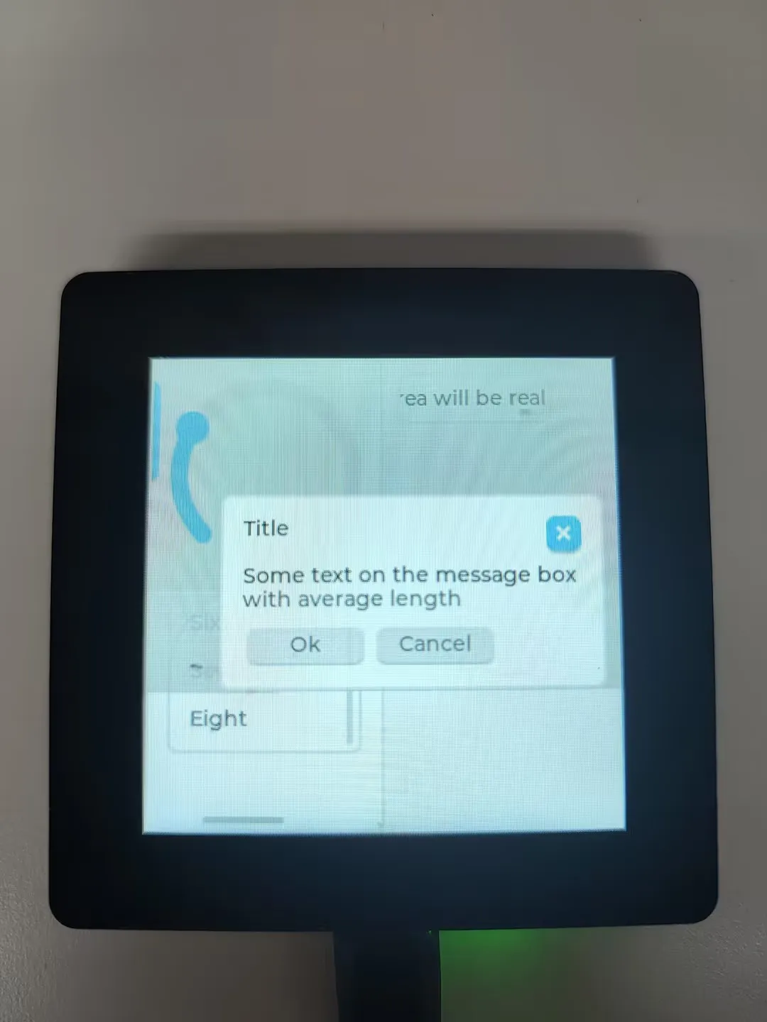
- The LCD displays the LVGL stress test interface.
- The serial port outputs
ESP32-C6-LCD-2.73 Arduino LVGL demoandLVGL stress demo started.
Troubleshooting
| Symptom | Possible Cause | Action |
|---|---|---|
Compilation error: lvgl.h not found | LVGL from the example package not installed | Copy code/arduino/libraries/lvgl to the Arduino libraries directory |
Compilation errors related to lv_disp_drv_t | LVGL v9 is being used | Delete the incorrect LVGL version and use LVGL v8.4.0 from the example package |
| Screen stays off | CH32V003, LCD reset, backlight, or ILI9488 initialization abnormal | Run 06_exio first to confirm CH32V003 is working; then restore the original pin configuration in 01_lvgl_demo |
| Display color abnormal | Pixel format or color order configuration modified | Keep bits_per_pixel = 18, LCD_RGB_ELEMENT_ORDER_BGR, and the color inversion configuration as provided in the example |
02_SD_Card
Function Description
This example verifies the TF card interface. The program mounts the TF card via SDSPI at the mount point /sd_card, then writes to sd_rw_test.txt and performs a read-back verification.
Code Entry
02_SD_Card/02_SD_Card.ino
02_SD_Card/sd_card_bsp.cpp
02_SD_Card/sd_card_bsp.h
Recommended key code sections:
| Code | Purpose |
|---|---|
PIN_NUM_CLK | TF SCLK, GPIO0 |
PIN_NUM_MOSI | TF MOSI, GPIO1 |
PIN_NUM_MISO | TF MISO, GPIO18 |
PIN_NUM_CS | TF CS, GPIO10 |
SD_card_Init() | Initialize SPI bus and mount TF card |
s_example_write_file() / s_example_read_file() | Example file write and read interfaces |
Expected Behavior
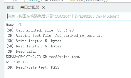
- After inserting a TF card formatted as FAT or FAT32, the serial port prints the TF card type, capacity, write length, read length, and a
PASSresult.
Troubleshooting
| Symptom | Possible Cause | Action |
|---|---|---|
| TF card mount fails | No card inserted, invalid format, or poor contact | Use a FAT/FAT32 TF card, re‑insert, and retest |
| File read/write fails | Mount failure or incorrect path | Confirm SD_card_Init() prints card info successfully |
| TF card abnormal after switching from LCD examples | SPI bus state or CS level not restored | Restart the board and run 02_SD_Card separately |
03_I2C_qmi8658
Function Description
This example reads the onboard QMI8658 6‑axis sensor. The program initializes I2C, creates the qmi8658c_example task, periodically reads accelerometer and gyroscope data, and outputs them via the serial port.
Code Entry
03_I2C_qmi8658/03_I2C_qmi8658.ino
03_I2C_qmi8658/i2c_bsp.cpp
03_I2C_qmi8658/qmi8658c.cpp
03_I2C_qmi8658/qmi8658c.h
Recommended key code sections:
| Code | Purpose |
|---|---|
I2C_master_Init() | Initializes I2C with SDA GPIO20, SCL GPIO2, 400 kHz |
QMI8658_SLAVE_ADDR_H | QMI8658 I2C address, default 0x6B |
qmi8658_init() | Initializes QMI8658 |
qmi8658_read_xyz() | Reads accelerometer and gyroscope data |
Expected Behavior
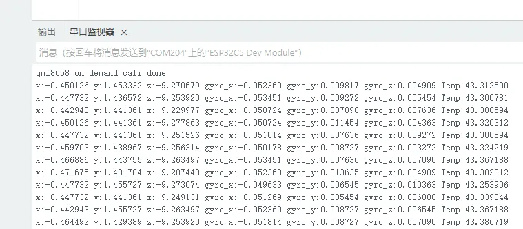
- The serial port first outputs QMI8658 initialization information, then periodically outputs sensor data.
- When the development board is slightly tilted or rotated, the accelerometer and gyroscope data will change accordingly.
Troubleshooting
| Symptom | Possible Cause | Action |
|---|---|---|
| Serial port indicates QMI8658 initialization failed | QMI8658 I2C communication failure | Confirm I2C pins are GPIO20/GPIO2; run 05_shtc3 or 06_exio first to verify I2C |
| Data remains unchanged | Board is stationary or task not running | Gently rotate the board and confirm the serial baud rate is 115200 |
| Compilation errors for I2C-related interfaces | Arduino ESP32 Core version mismatch | Use a board support package that includes ESP32-C6 support |
04_I2C_pcf85063
Function Description
This example verifies the onboard PCF85063 RTC. The program initializes the RTC and calls the following in setup():
i2c_rtc_setTime(2025, 9, 9, 14, 51, 30);
It then creates an i2c_rtc_loop_task task that reads and prints RTC time every second.
Code Entry
04_I2C_pcf85063/04_I2C_pcf85063.ino
04_I2C_pcf85063/rtc_bsp.cpp
04_I2C_pcf85063/rtc_bsp.h
Recommended key code sections:
| Code | Purpose |
|---|---|
rtc.begin(Wire, SENSOR_SDA, SENSOR_SCL) | Initializes PCF85063 with SDA GPIO20, SCL GPIO2 |
i2c_rtc_setTime() | Sets RTC time |
i2c_rtc_get() | Reads RTC time structure |
i2c_rtc_loop_task() | Periodically reads and prints RTC time over serial |
Expected Behavior
- The serial port outputs the RTC time once per second.
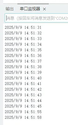
Since the example writes a fixed test time on every power‑up, if you want to verify continuous RTC time‑keeping, comment out or delete i2c_rtc_setTime().
Troubleshooting
| Symptom | Possible Cause | Action |
|---|---|---|
Compilation error: SensorPCF85063.hpp not found | Missing SensorLib dependency | Install SensorLib and recompile |
Serial shows Failed to find PCF85063 | RTC I2C communication failure | Confirm I2C pins are GPIO20/GPIO2; test other I2C examples first |
| Time always resets to fixed value on power‑up | Example actively writes test time | Comment out or delete i2c_rtc_setTime() and retest |
05_shtc3
Function Description
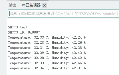
This example reads the onboard SHTC3 temperature and humidity sensor. The program uses Wire to send SHTC3 commands, wakes the sensor, reads its ID, performs a soft reset, and reads temperature and humidity every second in loop().
CRC checking is implemented to prevent invalid data from being treated as normal temperature/humidity readings.
Code Entry
05_shtc3/05_shtc3.ino
Recommended key code sections:
| Code | Purpose |
|---|---|
I2C_SDA / I2C_SCL | I2C pins, SDA GPIO20, SCL GPIO2 |
SHTC3_ADDR | SHTC3 I2C address, default 0x70 |
SHTC3_CMD_READ_ID | Reads sensor ID |
SHTC3_CMD_MEASURE_T_RH | Triggers temperature/humidity measurement |
shtc3Crc() | CRC check for SHTC3 data |
readShtc3() | Reads and converts temperature and humidity |
Expected Behavior
- The serial port first outputs the SHTC3 ID, then periodically outputs temperature and humidity.
Troubleshooting
| Symptom | Possible Cause | Action |
|---|---|---|
Serial shows SHTC3 not found | I2C communication failure | Confirm I2C pins are GPIO20/GPIO2 and ensure the board is powered |
Serial shows Failed to read SHTC3 | CRC failure or sensor not responding | Keep power stable, power cycle, and retest |
| Occasional abnormal temperature/humidity values | Invalid I2C data | The example includes CRC checking; use data that passes the check |
06_exio
Function Description
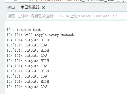
This example verifies communication with the onboard CH32V003 I/O expander. The CH32V003 communicates with ESP32-C6 via I2C at address 0x24. The example configures IO4-IO14 as outputs and toggles their levels once per second.
CH32V003 is pre‑programmed with firmware at the factory; no separate CH32 firmware flashing is required.
Code Entry
06_exio/06_exio.ino
06_exio/io_extension.cpp
06_exio/io_extension.h
Recommended key code sections:
| Code | Purpose |
|---|---|
Wire.begin(I2C_SDA, I2C_SCL) | Initialize I2C with SDA GPIO20, SCL GPIO2 |
IO_EXTENSION_ADDR | CH32V003 I2C, default 0x24 |
IO_EXTENSION_Init(Wire) | Initialize the I/O expander |
IO_EXTENSION_IO_Mode(0xFFF7) | Configure IO expansion pin modes |
IO_EXTENSION_Output() | Set output level for specific IO expansion pins |
Expected Behavior
- The serial port outputs
IO4-IO14 will toggle every second. - Then outputs the current levels of IO4-IO14 once per second.
Troubleshooting
| Symptom | Possible Cause | Action |
|---|---|---|
Serial shows IO extension not found at 0x24 | I2C communication failure | Confirm SDA GPIO20, SCL GPIO2 and ensure the board is powered |
| LCD subsequently malfunctioning | CH32V003 not communicating properly | First ensure 06_exio runs normally, then troubleshoot display and backlight |
| Need to re‑flash CH32V003 firmware | Not required | CH32V003 is pre-flashed from the factory; no action required for normal use |
07_example
Function Description
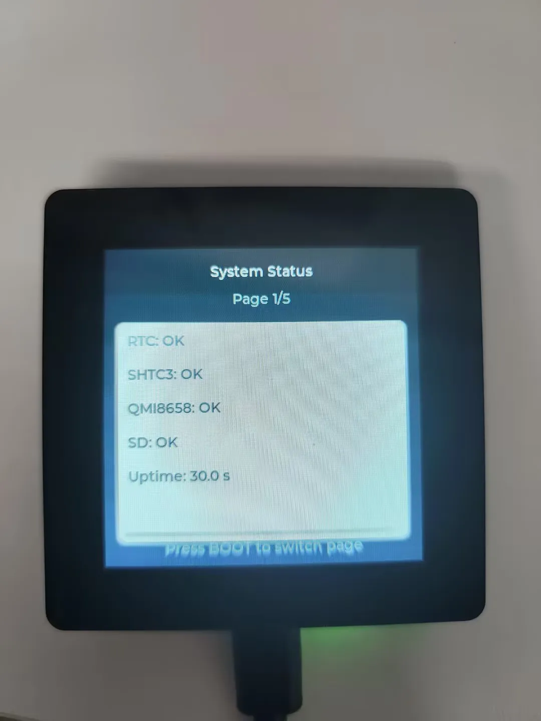
This example is used to comprehensively verify the LCD, backlight, RTC, SHTC3, QMI8658, and TF card. Upon startup, the program initializes I2C, CH32V003, ILI9488, LVGL, and onboard peripherals. The LCD displays system status, RTC, temperature/humidity, IMU, and TF card information.
Press the BOOT button to switch pages.
Code Entry
07_example/07_example.ino
07_example/esp_lcd_ili9488.c
07_example/esp_lcd_ili9488.h
07_example/i2c_bsp.cpp
07_example/qmi8658c.cpp
07_example/rtc_bsp.cpp
07_example/sd_card_bsp.cpp
07_example/lv_conf.h
Recommended key code sections:
| Code | Purpose |
|---|---|
init_lcd_panel() | Initialize SPI bus and ILI9488 panel |
init_lvgl() | Initialize LVGL display buffer and refresh callback |
init_peripherals() | Sequentially check RTC, SHTC3, QMI8658, and TF card |
refresh_sensors() | Periodically read sensor and RTC data |
refresh_screen() | Refresh LCD display content according to the current page |
handle_button() | Read GPIO9 BOOT button and switch pages |
Expected Behavior
- The LCD displays the
System Statuspage. - Pressing the BOOT button toggles the page among System Status, RTC, SHTC3, QMI8658 IMU, and TF Card.
- The serial port periodically outputs RTC, temperature/humidity, accelerometer, gyroscope, and TF card capacity information.
Troubleshooting
| Symptom | Possible Cause | Action |
|---|---|---|
Compilation error: lvgl.h not found | LVGL from the example package not installed | Copy code/arduino/libraries/lvgl to the Arduino libraries directory |
Compilation error: SensorPCF85063.hpp not found | Missing SensorLib dependency | Install SensorLib and recompile |
Page displays a peripheral as NO | Peripheral initialization or communication failure | Run the corresponding basic example for that peripheral separately first |
| BOOT button cannot switch pages | Button GPIO configuration abnormal | Confirm the example retains BOOT_BUTTON = GPIO_NUM_9 and INPUT_PULLUP configuration |
| TF page shows unmounted | TF card not inserted or format invalid | Insert a FAT/FAT32 formatted TF card and restart the board for testing |