Working with ESP-IDF
This chapter includes the following sections, please read as needed:
ESP-IDF Getting Started
New to ESP32 ESP-IDF development and looking to get started quickly? We have prepared a general Getting Started Tutorial for you.
- Section 1: Environment Setup
- Section 2: Running Examples
- Section 3: Creating a Project
- Section 4: Using Components
- Section 5: Debugging
- Section 6: FreeRTOS
- Section 7: Peripherals
- Section 8: Wi-Fi Programming
- Section 9: BLE Programming
Please Note: This tutorial uses the ESP32-S3-Zero as a teaching example, and all hardware code is based on its pinout. Before you start, it is recommended that you check the pinout of your development board to ensure the pin configuration is correct.
Setting Up the Development Environment
Please refer to Install ESP-IDF Development Environment.
The ESP32-C6-LCD-2.73 examples use ESP-IDF v5.5.3, with the project target chip set to esp32c6. If using other ESP-IDF versions, please refer to the dependencies.lock and sdkconfig files in the example project.
The following guide uses Windows as an example, demonstrating development using VS Code + the ESP-IDF extension. macOS and Linux users should refer to the official documentation.
The screenshots in this section use ESP-IDF V5.5.2 as an example. When installing, please select the ESP-IDF version that matches your board's example.
Install the ESP-IDF Development Environment
-
Download the installation manager from the ESP-IDF Installation Manager page. This is Espressif's latest cross-platform installer. The following steps demonstrate how to use its offline installation feature.
Click the Offline Installer tab on the page, then select Windows as the operating system and the ESP-IDF version you need (the version shown in the screenshot is for reference only — choose the version that fits your actual needs).
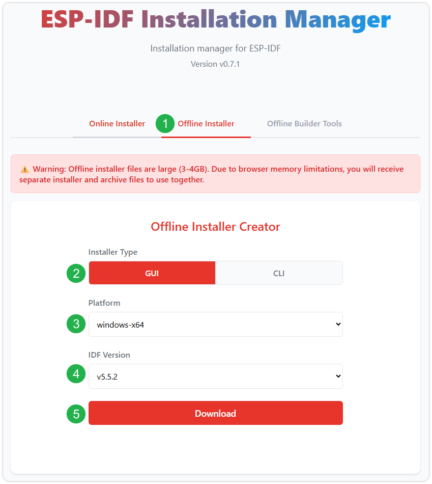
After confirming your selection, click the download button. The browser will automatically download two files: the ESP-IDF Offline Package (.zst) and the ESP-IDF Installer (.exe).
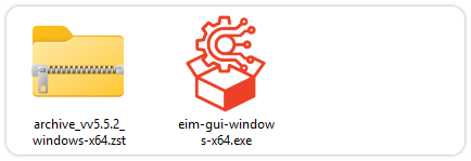
Please wait for both files to finish downloading.
-
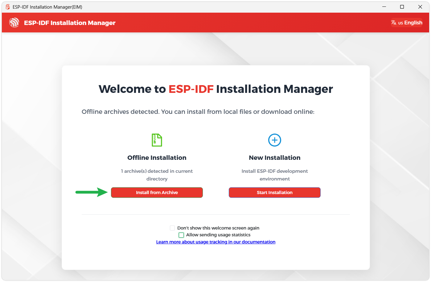
Once the download is complete, double-click to run the ESP-IDF Installer (eim-gui-windows-x64.exe).
The installer will automatically detect if the offline package exists in the same directory. Click Install from archive.
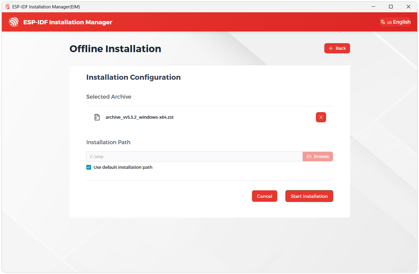
Next, select the installation path. We recommend using the default path. If you need to customize it, ensure the path does not contain Chinese characters or spaces. Click Start installation to proceed.
-
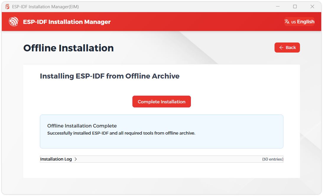
When you see the following screen, the ESP-IDF installation is successful.
-
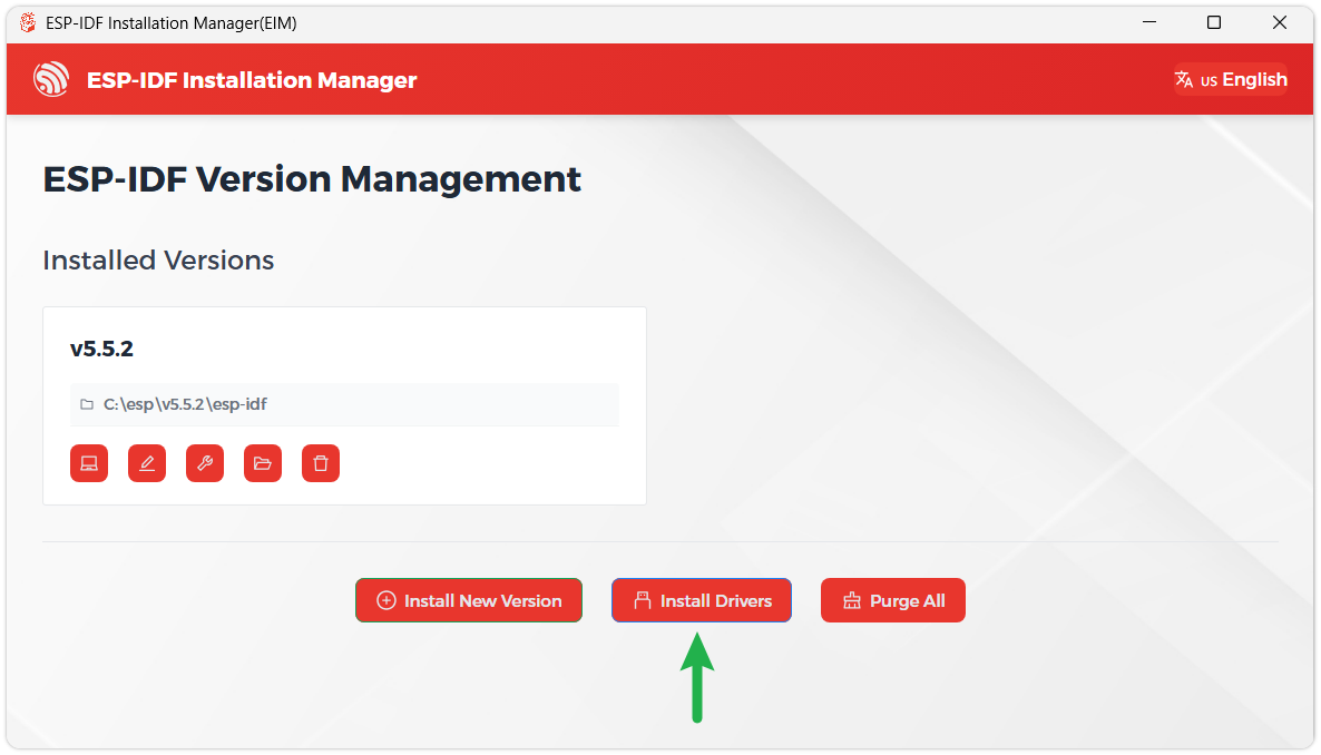
We recommend installing the drivers as well. Click Finish installation, then select Install driver.
Install Visual Studio Code and the ESP-IDF Extension
-
Download and install Visual Studio Code.
-
During installation, it is recommended to check Add "Open with Code" action to Windows Explorer file context menu to facilitate opening project folders quickly.
-
In VS Code, click the Extensions icon
 in the Activity Bar on the side (or use the shortcut Ctrl + Shift + X) to open the Extensions view.
 -
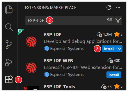
Enter ESP-IDF in the search box, locate the ESP-IDF extension, and click Install.
-
For ESP-IDF extension versions ≥ 2.0, the extension will automatically detect and recognize the ESP-IDF environment installed in the previous steps, requiring no manual configuration.
Example
The ESP-IDF example programs are located in the code/idf directory of the example program package. Each example project has been adapted to the onboard hardware resources of the ESP32-C6-LCD-2.73 and can be used to verify functions such as LCD, LVGL, TF, QMI8658, PCF85063, SHTC3, and CH32V003 IO expansion.
Building and Flashing
Navigate to any ESP-IDF example directory and run:
cd code/idf/02_lvgl_demo
idf.py build flash monitor
If you need to specify a serial port, replace COMx with the actual port, for example COM5:
idf.py -p COMx build flash monitor
Board Resources
| Feature | Device or Interface | Pins or Notes |
|---|---|---|
| LCD | ILI9488, SPI, 320 x 320, RGB666 | SCLK GPIO0, MOSI GPIO1, MISO GPIO18, DC GPIO19, CS GPIO8 |
| LCD Reset | CH32V003 I/O Expander | IO0 |
| LCD Backlight | CH32V003 PWM | IO Expansion PWM |
| I/O Expander | CH32V003, I2C address 0x24 | SDA GPIO20, SCL GPIO2 |
| 6‑axis IMU | QMI8658, I2C address 0x6B | SDA GPIO20, SCL GPIO2 |
| RTC | PCF85063, I2C address 0x51 | SDA GPIO20, SCL GPIO2 |
| Temp/Humidity Sensor | SHTC3, I2C address 0x70 | SDA GPIO20, SCL GPIO2 |
| TF | SDSPI | SCLK GPIO0, MOSI GPIO1, MISO GPIO18, CS GPIO10 |
| BOOT Button | User Button | GPIO9 |
Example List
| Example Directory | Description |
|---|---|
| 01_factory | Factory example, featuring main menu, settings, sensor, photo, and weather pages |
| 02_lvgl_demo | Initialize LCD and LVGL, runs the LVGL benchmark example |
| 03_sd_card | Mount TF card, writes and reads back a test file |
| 04_qmi8658 | Read QMI8658 accelerometer and gyroscope data, and outputs them via serial port |
| 05_pcf85063 | Read PCF85063 RTC time and output it periodically via serial port |
| 06_shtc3 | Read SHTC3 temperature and humidity data, and output them periodically via serial port |
| 07_exio | Test CH32V003 IO expansion by cyclically toggling IO4-IO14 output levels |
Usage Notes
- For secondary development, we recommend modifying the application layer or UI logic first. The BSP already defines and initializes the basic hardware resources and low-level interfaces of the development board. Only modify BSP-related code when changing hardware connections, adjusting low-level drivers, or adapting new peripherals.
01_factoryand02_lvgl_demouse LVGL v9.5.0 andesp_lvgl_adapter.- For
01_factoryand03_sd_card, it is recommended to insert a TF card formatted as FAT or FAT32 before running. - The Photo page of
01_factoryreads.jpgor.jpegimages from the/sdcard/photodirectory by default. - This product shares a single I2C bus:
SDA GPIO20,SCL GPIO2. CH32V003, QMI8658, PCF85063, and SHTC3 are all on this I2C bus. - Example 07 is an EXIO expansion IO test, primarily used to observe IO outputs or serial port status; it does not include an operational effect image.
01_factory
Example Description
- This example is the factory application example. Upon startup, it initializes NVS, TF, CH32V003 IO expansion, PCF85063 RTC, LCD, LVGL, and the application menu.
- The program synchronizes the system time from the RTC and displays the time and Wi-Fi status in the status bar.
- The menu registers the Settings, Sensor, Photo, and Weather applications.
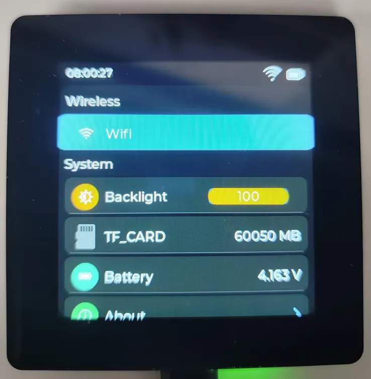
- The Settings page includes items such as Wi-Fi, Backlight, TF Card Capacity, Battery Info, and About.
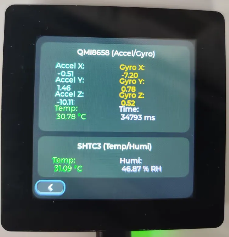
- The Sensor page displays QMI8658 accelerometer and gyroscope data, as well as SHTC3 temperature and humidity data.
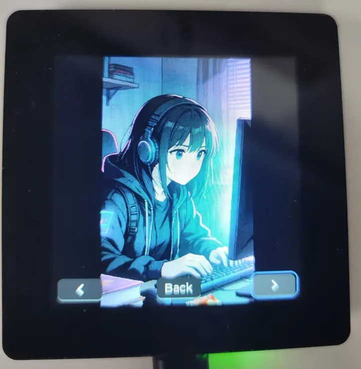
- The Photo page reads JPG images from the
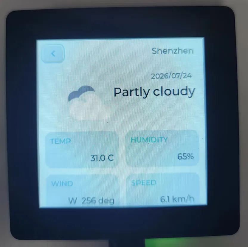
/sdcard/photodirectory and provides Previous, Next, and Back controls. - The Weather page is used to display weather information; Wi-Fi must first be configured via the Settings page.
Hardware Connection
- Connect the board to your computer via USB.
- To use the Photo page, insert a TF card formatted as FAT or FAT32, create a
photodirectory on the TF card, and place.jpgor.jpegimages inside. - To use the Weather page, configure Wi-Fi with internet access.
Code Entry
01_factory/main/main.c
01_factory/components/app_settings
01_factory/components/app_sensor
01_factory/components/app_photo
01_factory/components/app_weather
01_factory/components/waveshare__esp32_c6_lcd_2_73
Recommended key code sections:
| Code | Purpose |
|---|---|
system_manage_service_init() | Initialize system management service |
bsp_sdcard_mount() | Mount TF card |
bsp_io_expander_init() | Initialize CH32V003 IO expansion |
bsp_pcf85063a_drv_init() | Initialize PCF85063 RTC |
bsp_display_start() | Initialize LCD and LVGL |
butmenu_register_app() | Register Settings, Sensor, Photo, Weather applications |
Expected Behavior
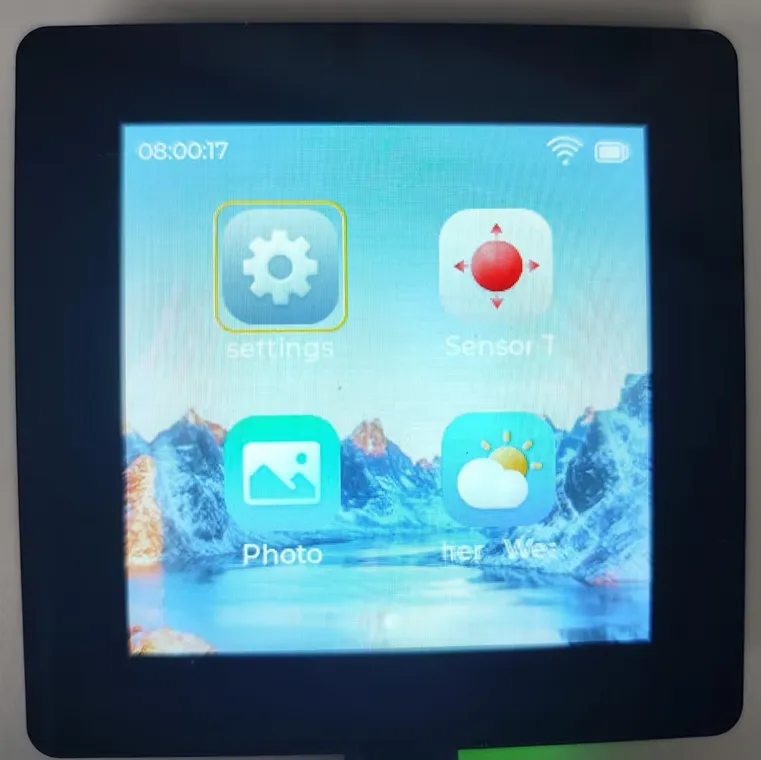
- The LCD displays the factory menu main interface.
- Pages for Settings, Sensor, Photo, and Weather can be accessed via buttons.
- The status bar updates the time every second, and the status icon changes after Wi-Fi connection.
| Main Page | Settings Page |
|---|---|
 |  |
| Sensor Page | Weather Page |
 |  |
| Photo Page | |
 |
Common Troubleshooting
| Symptom | Possible Cause | Action |
|---|---|---|
| Photo page indicates no images | TF card not mounted, directory does not exist, or image format mismatch | Confirm the /photo directory exists on the TF card and place .jpg or .jpeg images inside |
| Weather page shows no data | Wi-Fi not connected or network unavailable | Configure Wi-Fi in the Settings page and confirm the hotspot has internet access |
| Sensor page shows no data | I2C peripheral initialization failed | Run 04_qmi8658, 05_pcf85063, 06_shtc3, and 07_exio separately first |
02_lvgl_demo
Example Description
- This example is used to verify the LCD, backlight, and LVGL graphics refresh.
- The program initializes NVS, CH32V003 IO expansion, ILI9488 LCD, LVGL, and backlight.
- After initialization, it calls
lv_demo_benchmark()to run the LVGL benchmark example.
Hardware Connection
- Connect the board to your computer via USB.
- The example uses the onboard LCD and backlight; no external modules are required.
Code Entry
02_lvgl_demo/main/main.c
02_lvgl_demo/components/waveshare__esp32_c6_lcd_2_73
Recommended key code sections to review:
| Code | Purpose |
|---|---|
bsp_io_expander_init() | Initialize CH32V003 IO expansion |
IO_EXTENSION_Output(IO_EXTENSION_IO_0, ...) | Control LCD reset |
bsp_display_start() | Initialize LCD and LVGL |
bsp_display_backlight_on() | Turns on backlight |
lv_demo_benchmark() | Run LVGL benchmark |
Expected Behavior
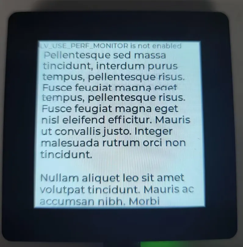
- The LCD displays the LVGL benchmark screen.
- The serial port outputs logs related to LCD, LVGL, and benchmark operations.
Common Troubleshooting
| Symptom | Possible Cause | Action |
|---|---|---|
| Screen stays off | CH32V003, LCD reset, backlight, or SPI initialization abnormal | Run 07_exio first, then restore the LCD-related pin definitions in the BSP |
| Display abnormal | LCD color format or resolution configuration modified | Confirm BSP_LCD_H_RES, BSP_LCD_V_RES are 320, and BSP_LCD_BITS_PER_PIXEL is 18 |
03_sd_card
Example Description
- This example is used to verify TF card read/write operations.
- The program first sets the LCD CS GPIO8 high to prevent chip select conflicts when the LCD and TF card share the SPI bus.
- It then calls
bsp_sdcard_mount()to mount the TF card at the mount point/sdcard. - Upon successful mounting, the program writes to
/sdcard/test.txt, then reads it back and verifies the content.
Hardware Connection
- Connect the board to your computer via USB.
- Insert a TF card formatted as FAT or FAT32.
Code Entry
03_sd_card/main/main.c
03_sd_card/components/waveshare__esp32_c6_lcd_2_73
Recommended key code sections to review:
| Code | Purpose |
|---|---|
BSP_LCD_CS | LCD CS, GPIO8, pulled high before test |
bsp_sdcard_mount() | Mount TF card |
BSP_SD_MOUNT_POINT | TF card mount point, default /sdcard |
tf_card_read_write_test() | Write, read back, and verify test file |
sdmmc_card_print_info() | Print TF card information |
Expected Behavior
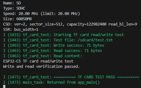
- The serial port prints TF card information.
- Upon passing the test, it outputs
TF CARD TEST PASS.
Common Troubleshooting
| Symptom | Possible Cause | Action |
|---|---|---|
| TF card mount fails | No card inserted, invalid format, or poor contact | Use a FAT/FAT32 TF card, re‑insert, and retest |
| File write or read-back failed | File system corrupted or card not writable | Replace the TF card or reformat it before testing again |
| Abnormal behavior after switching from LCD examples | SPI bus or chip select state not restored | Restart the board and run 03_sd_card separately |
04_qmi8658
Example Description
- This example is used to verify the onboard QMI8658 6-axis sensor.
- The program calls
bsp_qmi8658_drv_init()to initialize QMI8658. - Data units are configured as acceleration
m/s^2and gyroscopedps. - The main loop checks the data ready status every 200 ms, reads the data, and outputs it via the serial port.
Hardware Connection
- Connect the board to your computer via USB.
- The example uses the onboard QMI8658; no external modules are required.
Code Entry
04_qmi8658/main/main.c
04_qmi8658/components/waveshare__esp32_c6_lcd_2_73
Recommended key code sections to review:
| Code | Purpose |
|---|---|
bsp_qmi8658_drv_init() | Initialize QMI8658 |
qmi8658_set_accel_unit_mps2() | Set acceleration unit to m/s^2 |
qmi8658_set_gyro_unit_dps() | Set gyroscope unit to dps |
qmi8658_is_data_ready() | Check if data is ready |
qmi8658_read_sensor_data() | Read accelerometer and gyroscope data |
Expected Behavior
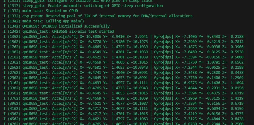
- The serial port periodically outputs accelerometer and gyroscope data.
- When the board is slightly tilted or rotated, the output data will change accordingly.
Common Troubleshooting
| Symptom | Possible Cause | Action |
|---|---|---|
| Initialization failed | I2C communication error | Confirm I2C uses SDA GPIO20, SCL GPIO2, and run 07_exio or 06_shtc3 first |
| Data remains unchanged | Board stationary or data not updated | Slightly rotate the board and confirm the serial monitor is running |
05_pcf85063
Example Description
- This example is used to verify the onboard PCF85063 RTC.
- The program calls
bsp_pcf85063a_drv_init()to initialize the RTC. - The main loop calls
pcf85063a_get_time_date()every second to read the date, time, and day of the week, and outputs them via the serial port.
Hardware Connection
- Connect the board to your computer via USB.
- The example uses the onboard PCF85063; no external modules are required.
Code Entry
05_pcf85063/main/main.c
05_pcf85063/components/waveshare__esp32_c6_lcd_2_73
Recommended key code sections to review:
| Code | Purpose |
|---|---|
bsp_pcf85063a_drv_init() | Initialize PCF85063 RTC |
pcf85063a_get_time_date() | Read RTC date and time |
pcf85063a_datetime_t | RTC date and time structure |
Expected Behavior
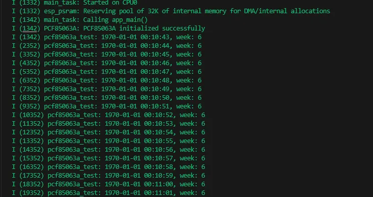
- The serial port outputs the RTC time once per second.
Common Troubleshooting
| Symptom | Possible Cause | Action |
|---|---|---|
| RTC read failed | PCF85063 I2C communication error | Confirm I2C uses SDA GPIO20, SCL GPIO2, and test other I2C examples |
| Time does not match expectations | RTC not set or battery power status abnormal | Run 01_factory first to synchronize the system time, or add RTC time setting logic to the code |
06_shtc3
Example Description
- This example is used to verify the onboard SHTC3 temperature and humidity sensor.
- The program delays for 1 second, then calls
bsp_shtc3_drv_init()to initialize SHTC3. - The main loop calls
shtc3_get_th()every second to read temperature and humidity, and outputs them via the serial port.
Hardware Connection
- Connect the board to your computer via USB.
- The example uses the onboard SHTC3; no external modules are required.
Code Entry
06_shtc3/main/main.c
06_shtc3/components/waveshare__esp32_c6_lcd_2_73
Recommended key code sections to review:
| Code | Purpose |
|---|---|
bsp_shtc3_drv_init() | Initialize SHTC3 |
shtc3_get_th() | Read temperature and humidity |
SHTC3_REG_T_CSD_NM | Temperature-first, normal mode measurement command |
Expected Behavior
- The serial port outputs temperature and humidity once per second.
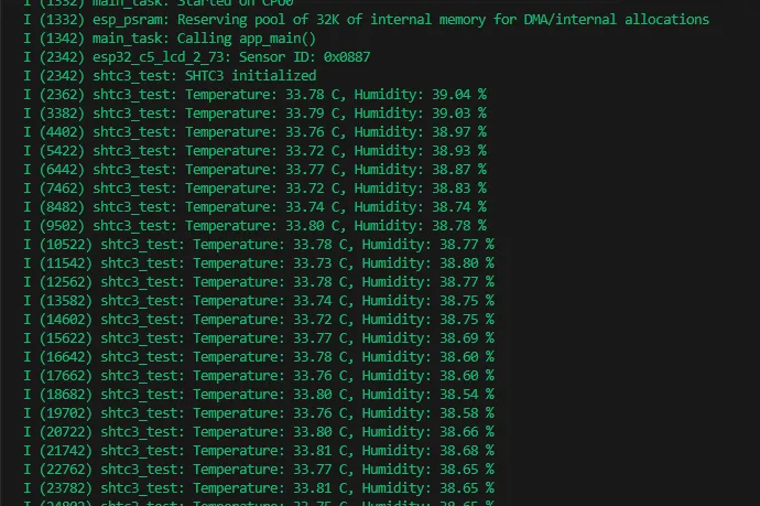
Common Troubleshooting
| Symptom | Possible Cause | Action |
|---|---|---|
| Initialization failed | SHTC3 I2C communication error | Confirm I2C uses SDA GPIO20, SCL GPIO2, and ensure the board is powered properly |
| Temperature/humidity read failed | Sensor did not respond correctly or I2C data error | Restart the board and test again; compare with 04_qmi8658 or 05_pcf85063 to check I2C status |
07_exio
Example Description
- This example is used to verify CH32V003 IO expansion output control.
- The program calls
bsp_io_expander_init()to initialize CH32V003. - The example configures the IO expansion pin mode to 0xFFF7, then toggles the output levels of IO4-IO14 once per second.
- The CH32V003 is pre-flashed with firmware from the factory; no separate flashing of the CH32 firmware is required.
Hardware Connection
- Connect the board to your computer via USB.
- The example uses the onboard CH32V003 IO expansion chip; no external modules are required.
Code Entry
07_exio/main/main.c
07_exio/components/waveshare__esp32_c6_lcd_2_73
Recommended key code sections to review:
| Code | Purpose |
|---|---|
bsp_io_expander_init() | Initialize CH32V003 IO expansion |
IO_EXTENSION_IO_Mode(0xFFF7) | Configure IO expansion pin modes |
IO_EXTENSION_Output() | Set output level for specific IO expansion pins |
IO_EXTENSION_IO_4 / IO_EXTENSION_IO_14 | Output toggle range |
Expected Behavior
- The output levels of IO4-IO14 toggle once per second.
- This example does not include an operational effect image.
Common Troubleshooting
| Symptom | Possible Cause | Action |
|---|---|---|
| Subsequent LCD or backlight examples malfunction | CH32V003 not communicating properly | First confirm 07_exio can run, then troubleshoot LCD reset and backlight control |
| IO output does not change | IO expansion initialization failed or output range modified | Keep IO_EXTENSION_IO_Mode(0xFFF7) and the IO4-IO14 output range as in the example |