ESP-IDF
This chapter contains the following sections. Please read as needed:
ESP-IDF Getting Started
New to ESP32 ESP-IDF development and looking to get started quickly? We have prepared a general Getting Started Tutorial for you.
- Section 1: Environment Setup
- Section 2: Running Examples
- Section 3: Creating a Project
- Section 4: Using Components
- Section 5: Debugging
- Section 6: FreeRTOS
- Section 7: Peripherals
- Section 8: Wi-Fi Programming
- Section 9: BLE Programming
Please Note: This tutorial uses the ESP32-S3-Zero as a teaching example, and all hardware code is based on its pinout. Before you start, it is recommended that you check the pinout of your development board to ensure the pin configuration is correct.
Setting Up Development Environment
Please refer to Install ESP-IDF Development Environment.
For the ESP32-C6-Touch-AMOLED-1.64 development board, ESP-IDF version 5.5.2 or above is required.
The following guide uses Windows as an example, demonstrating development using VS Code + the ESP-IDF extension. macOS and Linux users should refer to the official documentation.
The screenshots in this section use ESP-IDF V5.5.2 as an example. When installing, please select the ESP-IDF version that matches your board's example.
Install the ESP-IDF Development Environment
-
Download the installation manager from the ESP-IDF Installation Manager page. This is Espressif's latest cross-platform installer. The following steps demonstrate how to use its offline installation feature.
Click the Offline Installer tab on the page, then select Windows as the operating system and the ESP-IDF version you need (the version shown in the screenshot is for reference only — choose the version that fits your actual needs).

After confirming your selection, click the download button. The browser will automatically download two files: the ESP-IDF Offline Package (.zst) and the ESP-IDF Installer (.exe).

Please wait for both files to finish downloading.
-
Once the download is complete, double-click to run the ESP-IDF Installer (eim-gui-windows-x64.exe).
The installer will automatically detect if the offline package exists in the same directory. Click Install from archive.

Next, select the installation path. We recommend using the default path. If you need to customize it, ensure the path does not contain Chinese characters or spaces. Click Start installation to proceed.

-
When you see the following screen, the ESP-IDF installation is successful.

-
We recommend installing the drivers as well. Click Finish installation, then select Install driver.

Install Visual Studio Code and the ESP-IDF Extension
-
Download and install Visual Studio Code.
-
During installation, it is recommended to check Add "Open with Code" action to Windows Explorer file context menu to facilitate opening project folders quickly.
-
In VS Code, click the Extensions icon
 in the Activity Bar on the side (or use the shortcut Ctrl + Shift + X) to open the Extensions view.
 -
Enter ESP-IDF in the search box, locate the ESP-IDF extension, and click Install.

-
For ESP-IDF extension versions ≥ 2.0, the extension will automatically detect and recognize the ESP-IDF environment installed in the previous steps, requiring no manual configuration.
Example
| Demo | Basic Description | Dependency Library |
|---|---|---|
| 01_ADC_Test | Get the lithium battery voltage value and display it on the screen | - |
| 02_I2C_QMI8658 | Print the raw data from the IMU | - |
| 03_SD_Card | Load and display TF card information, and perform read/write tests | - |
| 04_WIFI_AP | Set to AP mode, can obtain the MAC address of connected devices | - |
| 05_WIFI_STA | Set to STA mode to connect to WiFi and obtain an IP address | - |
| 06_LVGL_Test | LVGL example | - |
| 07_brookesia_app | Brookesia picture APP example | - |
01_ADC_Test
Description
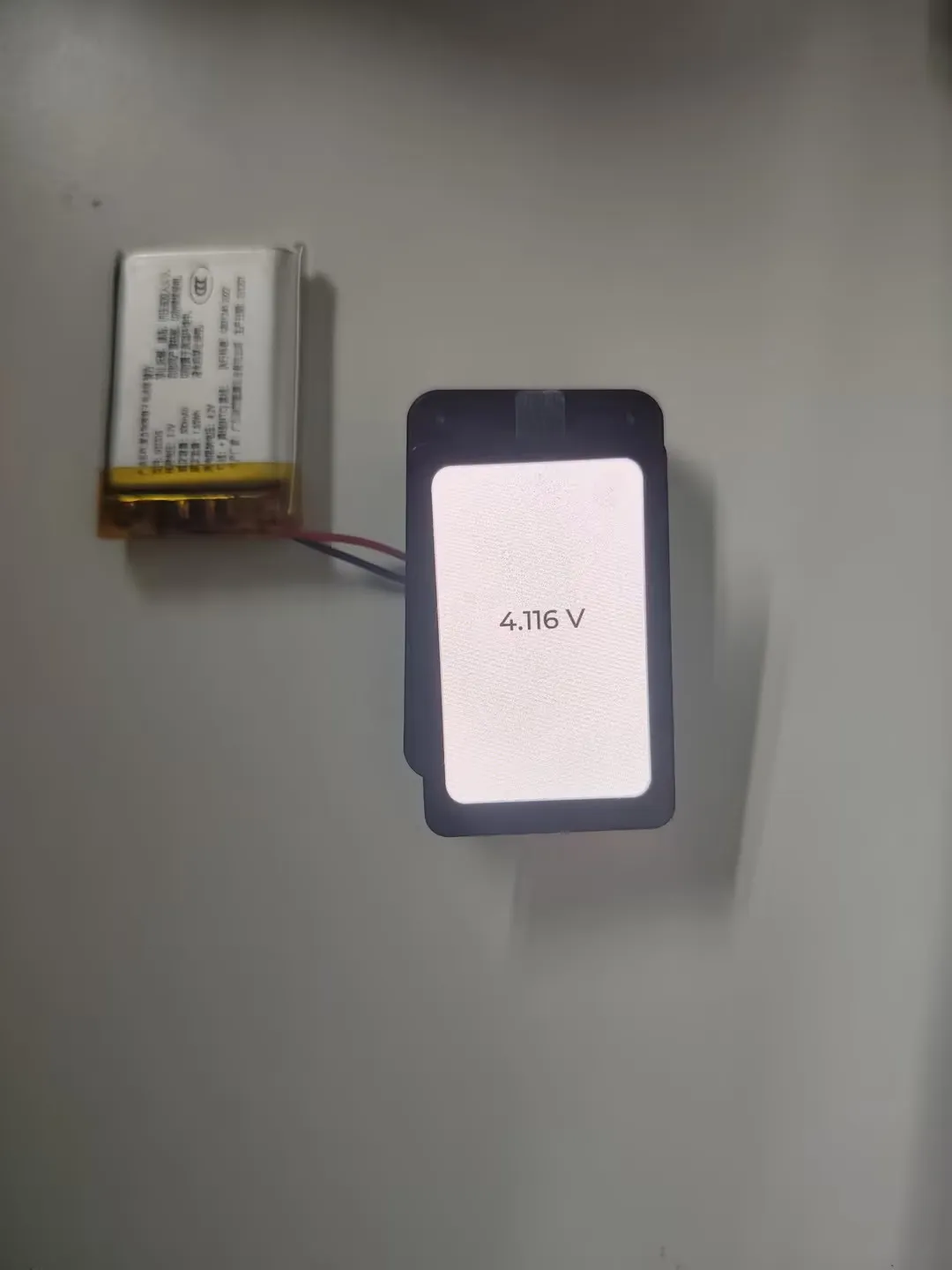
- The analog voltage connected via GPIO is converted to a digital value by the ADC, then the actual system voltage is calculated and displayed on the screen.
Hardware Connection
- Connect a 3.7V lithium battery
Code Analysis
bsp_display_start(): Initialize the screen, touch, and LVGLbsp_display_backlight_on(): Turn on the backlightbat_adc_init(): Initialize ADC1, including creating an ADC single-shot trigger unit and configuring ADC1 channel 0.
Operation Result
-
After compiling and downloading the program, connect the battery. The battery voltage will be displayed on the screen as shown in the figure below:
02_I2C_QMI8658
Description
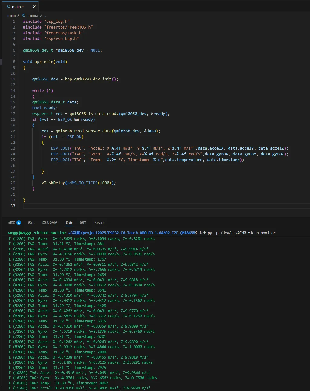
- Initializes the QMI8658 chip via the I2C protocol, then reads and prints the corresponding attitude information to the terminal every 1 second.
Hardware Connection
- Connect a 3.7V lithium battery
Code Analysis
bsp_qmi8658_drv_init(): Initialize qmi8658qmi8658_is_data_ready(): Check if data is readyqmi8658_read_sensor_data(): Read gyroscope data
Operation Result
-
After the program is flashed, the device operation result is as follows:
03_SD_Card
Description
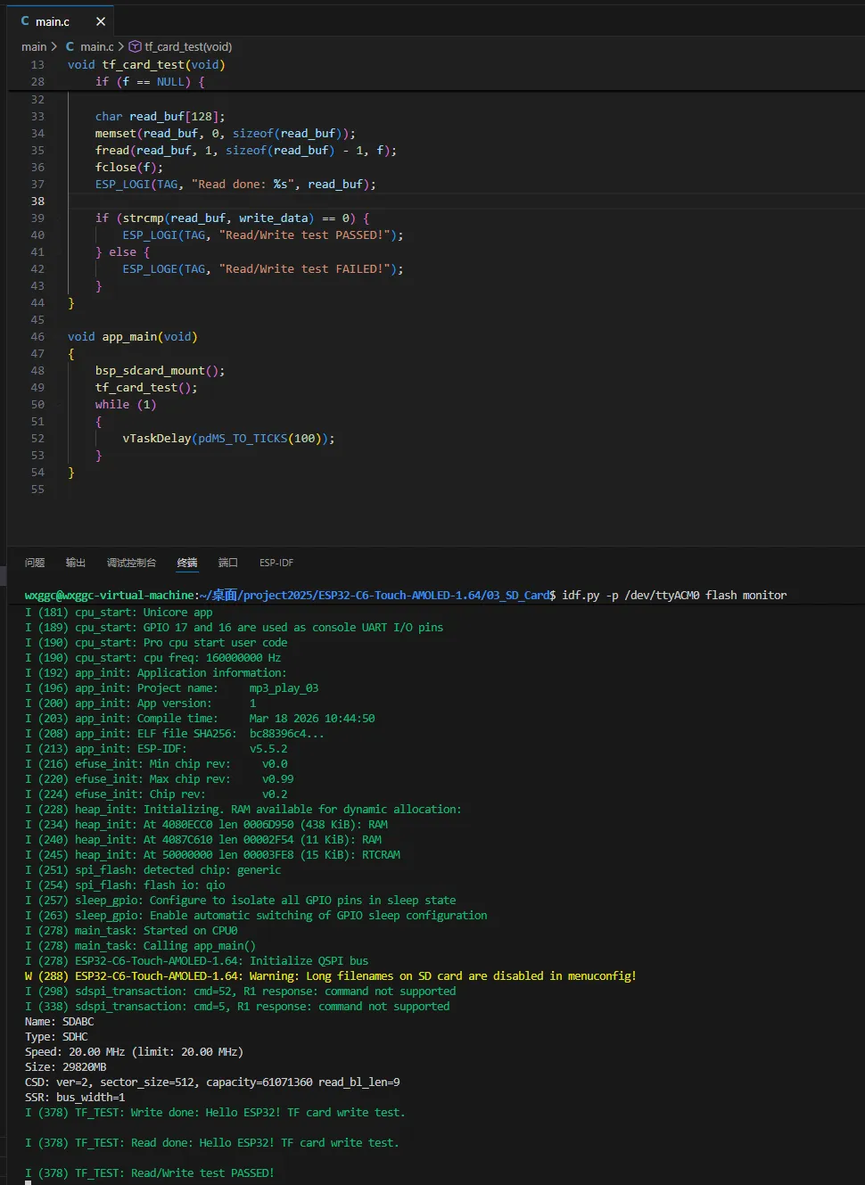
- Drives the TF card via SPI. After successfully mounting the TF card, prints the TF card information and read/write file test results to the terminal.
Hardware Connection
- The board must have a TF card inserted (capacity less than 64GB)
- Connect the board to the computer using a USB cable
Code Analysis
bsp_sdcard_mount(): Initialize the TF card via the SPI interfacetf_card_test(): Read/write file test
Operation Result
-
Click on the Serial Monitor to see the output TF card information:
04_WIFI_AP
Description
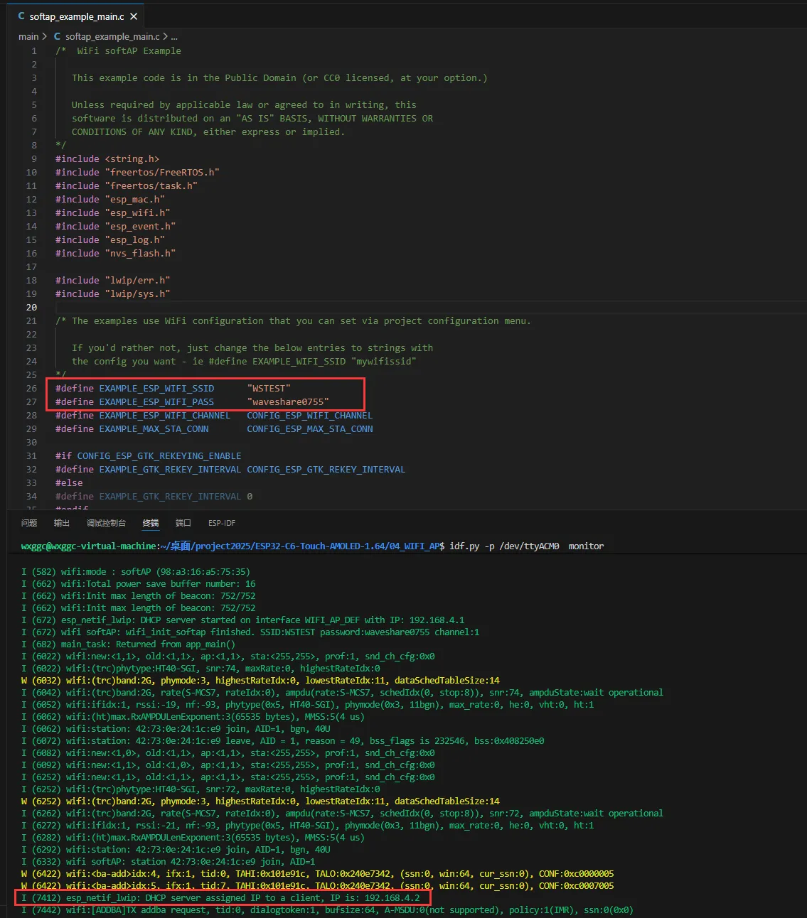
- This demo can set the development board as a hotspot, allowing phones or other devices in STA mode to connect to the development board.
Hardware Connection
- Connect the board to the computer using a USB cable
Code Analysis
- Find
SSIDandPASSWORDin thesoftap_example_main.cfile. Then mobile phones or other devices in STA mode can use thisSSIDandPASSWORDto connect to the development board.
Operation Result
-
Click on the Serial Monitor. If a device successfully connects to the hotspot, the IP address of that device will be output:
05_WIFI_STA
Description
- This example configures the development board as a STA device to connect to a router, thereby accessing the system network.
Hardware Connection
- Connect the board to the computer using a USB cable
Code Analysis
- Find
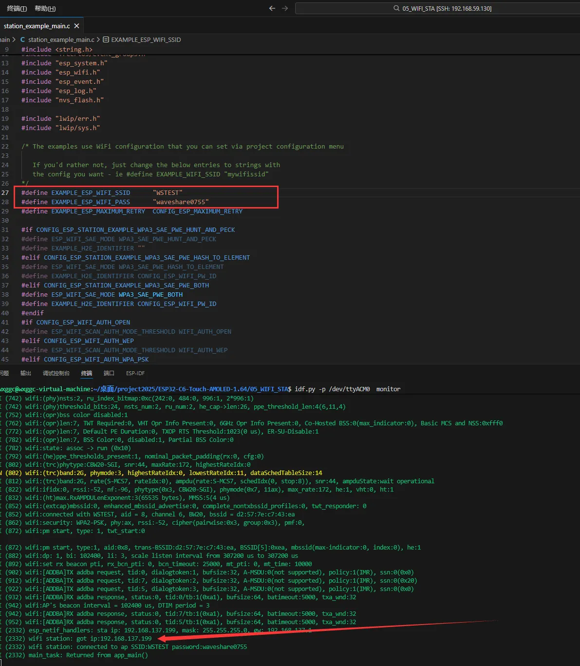
SSIDandPASSWORDin thestation_example_main.cfile, and modify them to theSSIDandPasswordof an available router in the current environment.
Operation Result
-
After flashing the program, open the Serial Terminal. If the device successfully connects to the hotspot, the obtained IP address will be output, as shown in the figure:
06_LVGL_Test
Description
- Implements multifunctional GUI interfaces on the screen by porting LVGL.
Hardware Connection
- Connect the board to the computer using a USB cable
Code Analysis
bsp_display_start(): Initialize the screen, touch, and LVGLbsp_display_backlight_on(): Turn on the backlightlv_demo_widgets(): Load the LVGL demo program
Operation Result
-
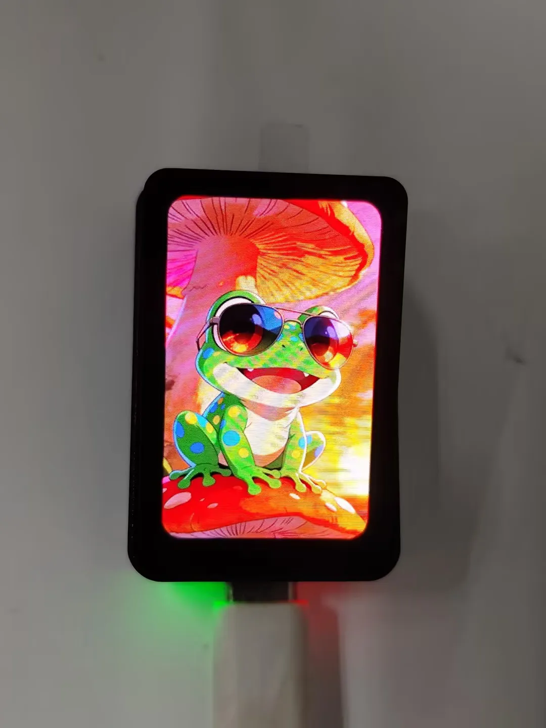
After the program is flashed, the device operation result is as follows:
07_brookesia_app
Description
- Implements APP-like functionality by porting
LVGLand Espressif'sbrookesiacomponent. This example only loads the picture APP.
Hardware Connection
- Connect the board to the computer using a USB cable
Code Analysis
-
Configure the LVGL lock for Brookesia
LvLock::registerCallbacks([](int timeout_ms) {esp_err_t ret = bsp_display_lock(timeout_ms);ESP_UTILS_CHECK_FALSE_RETURN(ret == ESP_OK, false, "Lock failed (timeout_ms: %d)", timeout_ms);return true;}, []() {bsp_display_unlock();return true;}); -
Install the APP
auto app4 = esp_brookesia::apps::Photos::requestInstance();ESP_UTILS_CHECK_FALSE_EXIT(phone->installApp(app4),"start Drawpanel failed");
Operation Result
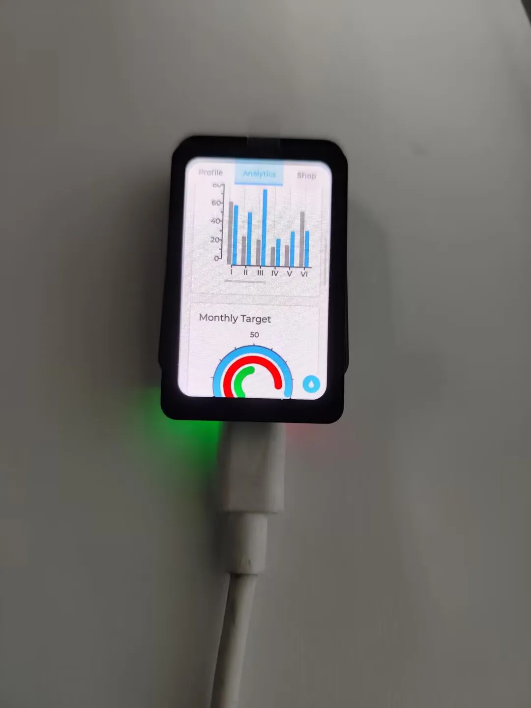
- After flashing the program, click the photo album icon. Swipe left or right to switch pictures. The device operation effect is as follows:
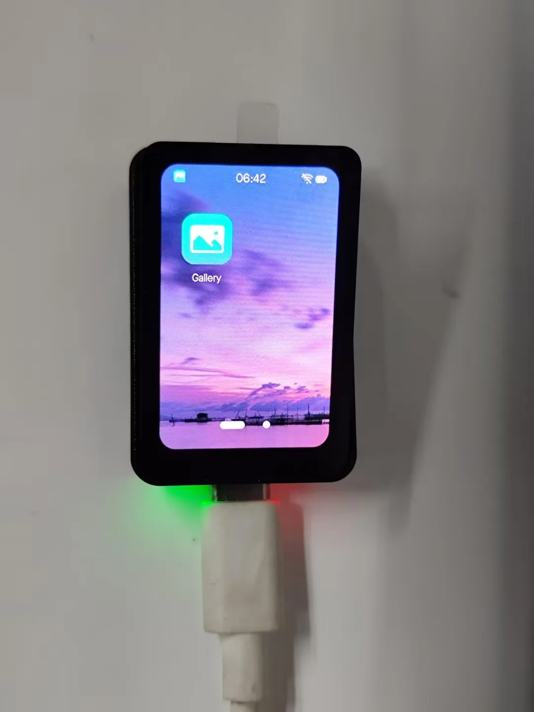 |  | 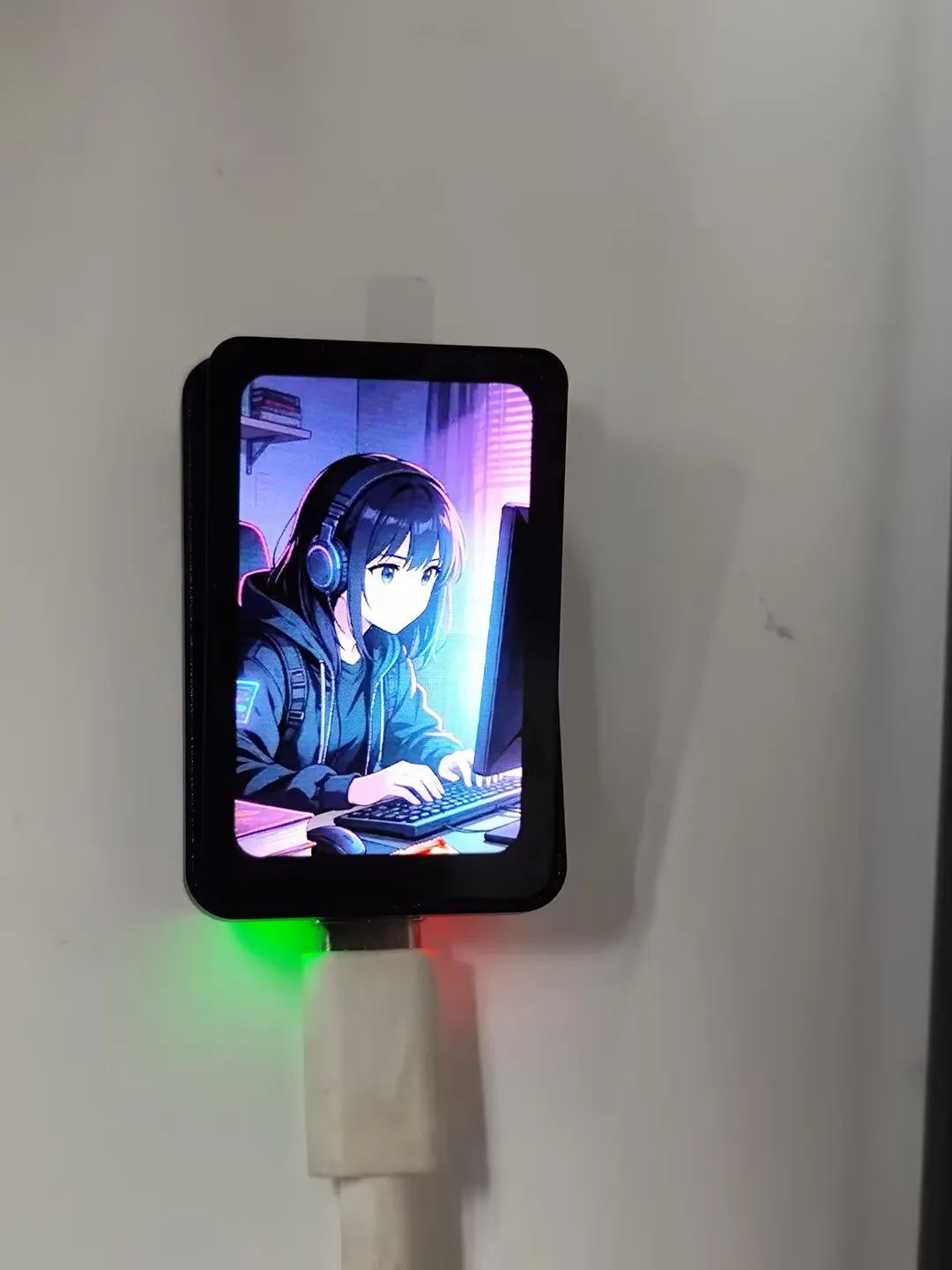 |
|---|