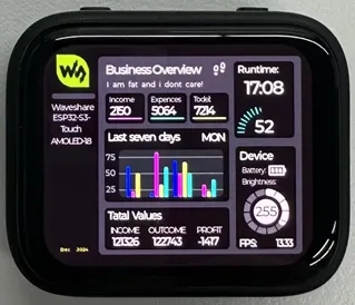
Working with Arduino
- V1 (SH8601 + FT3168/FT6146, using the FT5x06 driver family): use
examples/arduino. - V2 (CO5300 + CST820): use
examples/arduino-v2.
The two versions share the same board-level interfaces and pins, but use different display and touch drivers. Always use sketches and bundled libraries from the same directory. Do not convert a V1 sketch to V2 by manually replacing driver classes.
This chapter includes the following sections, please read as needed:
Arduino Getting Started Tutorial
New to Arduino ESP32 development and looking for a quick start? We have prepared a comprehensive Getting Started Tutorial for you.
- Section 0: Getting to Know ESP32
- Section 1: Installing and Configuring Arduino IDE
- Section 2: Arduino Basics
- Section 3: Digital Output/Input
- Section 4: Analog Input
- Section 5: Pulse Width Modulation (PWM)
- Section 6: Serial Communication (UART)
- Section 7: I2C Communication
- Section 8: SPI Communication
- Section 9: Wi-Fi Basics
- Section 10: Web Server
- Section 11: Bluetooth
- Section 12: LVGL GUI Development
- Section 13: Comprehensive Project
Note: This tutorial uses the ESP32-S3-Zero as a reference example, and all hardware code is based on its pinout. Before you start, we recommend checking the pinout of your development board to ensure the pin configuration is correct.
Setting Up Development Environment
1. Installing and Configuring Arduino IDE
Please refer to the tutorial Installing and Configuring Arduino IDE Tutorial to download and install the Arduino IDE and add ESP32 support.
The repository CI compiles both example sets with Arduino-ESP32 3.3.11 and the FQBN esp32:esp32:esp32c6:FlashSize=16M,PartitionScheme=app3M_fat9M_16MB. The Arduino matrix contains 23 jobs: 14 for V1 and 9 for V2. Use the same core version and board configuration when reproducing the examples.
2. Installing Libraries
- Download the product repository and select the directory matching your board version.
- Each example set includes its tested libraries under its own
librariesdirectory. Copy only the matching library folders into the Arduino sketchbooklibrariesdirectory, or configure your build tool to use that directory directly. Auxiliary dependencies such asAdafruit_XCA9554andAdafruit_BusIOare also included in the matching directory. - When switching versions, replace the previous version's bundled libraries. Do not keep incompatible libraries with the same names or substitute global Library Manager versions unless the example README explicitly allows it.
| Library/File Name | Description | Version | Installation Method |
|---|---|---|---|
| GFX_Library_for_Arduino | SH8601 or CO5300 display support, depending on the selected bundle | Repository bundle | Install from the matching example directory |
| Arduino_DriveBus | FT3168/FT6146 (FT5x06 driver family) or CST820 support through a compatible touch driver, depending on the selected bundle | Repository bundle | Install from the matching example directory |
| SensorLib | PCF85063 and QMI8658 support | Repository bundle | Install from the matching example directory |
| XPowersLib | AXP2101 power management support | Repository bundle | Install from the matching example directory |
| lvgl and support files | LVGL framework, configuration, and example UI files | Repository bundle | Install from the matching example directory |
The bundled libraries are tested together with their corresponding V1 or V2 examples. Mixing the two bundles, or mixing their LVGL and driver versions with unrelated global installations, may cause compilation failures or incorrect display and touch behavior.
Installation Steps:
-
Download the product repository.
-
For V1, copy the library folders from
examples/arduino/libraries; for V2, useexamples/arduino-v2/libraries.infoIn Arduino IDE, open File > Preferences and check Sketchbook location. The target is the
librariesfolder under that sketchbook directory. -
For other installation methods, please refer to: Arduino Library Management Tutorial.
Example
The repository provides two independent example sets:
- V1 examples for SH8601 + FT3168/FT6146 (FT5x06 driver family).
- V2 examples for CO5300 + CST820.
The example descriptions and screenshots below document the V1 set. V2 users should open the corresponding sketch under examples/arduino-v2/examples; its bundled code already selects the CO5300 display driver and a CST820-compatible touch driver, so no driver-class edits are required.
V1 Example Reference
| Example | Basic Program Description | Dependency Library |
|---|---|---|
| 01_HelloWorld | Demonstrates the basic graphics library function and can also be used to test the basic performance of display screens and the display effect of random text | GFX_Library_for_Arduino |
| 02_Drawing_board | Demonstrates the basic graphics library functions and can also be used to test the basic performance of display screens and the display effect of random text | GFX_Library_for_Arduino, Arduino_DriveBus, Adafruit_XCA9554 |
| 03_GFX_AsciiTable | Prints ASCII characters in rows and columns on the screen according to the screen size | GFX_Library_for_Arduino |
| 04_GFX_FT3168_Image | Shows image display effects, switching displayed images via touch | GFX_Library_for_Arduino, Arduino_DriveBus, Adafruit_XCA9554 |
| 05_GFX_PCF85063_simpleTime | GFX library displays the current time | SensorLib, GFX_Library_for_Arduino |
| 06_GFX_ESPWiFiAnalyzer | Draws WiFi band signal strength on the screen | GFX_Library_for_Arduino |
| 07_GFX_Clock | Implements a clock using simple marker pointers and time management | GFX_Library_for_Arduino |
| 08_LVGL_Animation | Custom UI to control backlight brightness | LVGL, Arduino_DriveBus, ui_a |
| 09_LVGL_change_background | Custom UI to control the background color | LVGL, Arduino_DriveBus, ui_b |
| 10_LVGL_PCF85063_simpleTime | LVGL library displays the current time | LVGL, SensorLib |
| 11_LVGL_QMI8658_ui | LVGL draws an acceleration line chart | LVGL, SensorLib |
| 12_LVGL_Widgets | LVGL demonstration | LVGL, Arduino_DriveBus, Adafruit_XCA9554 |
| 13_ES8311 | ES8311 driver example, plays simple audio | —— |
| 14_LVGL_Sqprj | SquareLine UI combined with LVGL example | LVGL |
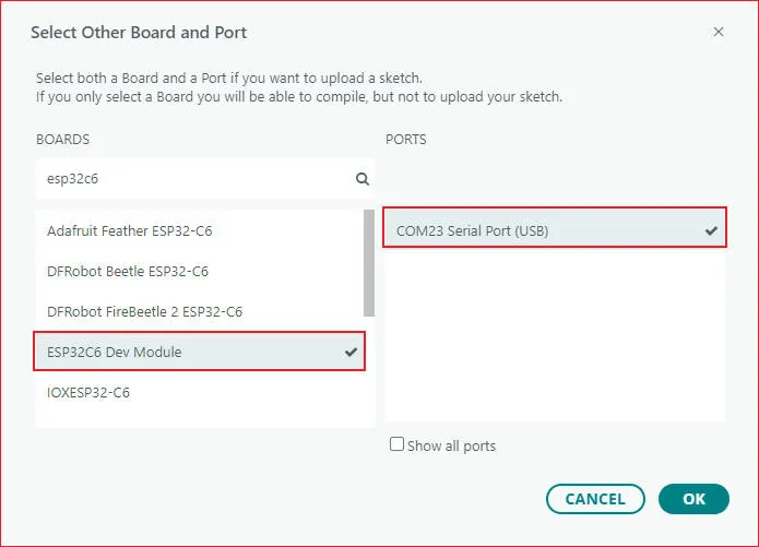
- ESP32-C6-Touch-AMOLED-1.8 select model
01_HelloWorld
Example Description
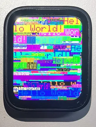
- This demo demonstrates how to control the SH8601 display using the Arduino GFX library, demonstrating basic graphics library functions through dynamically changing text. This code can also be used to test the basic performance of the display and the random text display effects
Hardware Connection
- Connect the development board to the computer
Code Analysis
-
Display initialization:
if (!gfx->begin()) {USBSerial.println("gfx->begin() failed!");} -
Clear the screen and display text:
gfx->fillScreen(BLACK);gfx->setCursor(10, 10);gfx->setTextColor(RED);gfx->println("Hello World!"); -
Animated display:
gfx->setCursor(random(gfx->width()), random(gfx->height()));gfx->setTextColor(random(0xffff), random(0xffff));gfx->setTextSize(random(6), random(6), random(2));gfx->println("Hello World!");
Execution Result
02_Drawing_board
Example Description
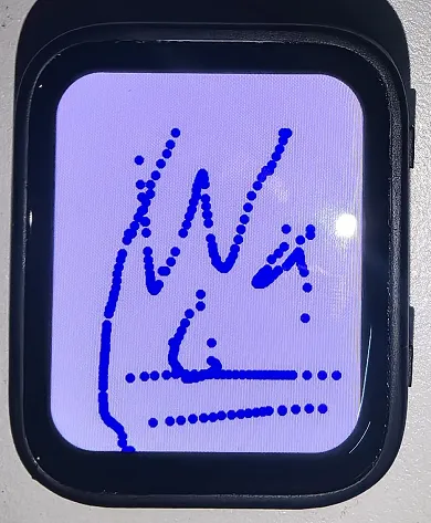
- This example demonstrates how to use the ESP32 to control the FT3168 touch controller and TCA9554 GPIO expander via the I2C interface, while using the Arduino GFX and Arduino_DriveBus libraries to drive the SH8601 display
Hardware Connection
- Connect the development board to the computer
Code Analysis
-
Display initialization and brightness fade animation:
gfx->begin();gfx->fillScreen(WHITE);for(int i = 0;i <= 255;i++){gfx->Display_Brightness(i);gfx->setCursor(30, 150);gfx->setTextColor(BLUE);gfx->setTextSize(4);gfx->println("Loading board");delay(3);} -
Touch interrupt handling and coordinate reading:
gfx->fillScreen(BLACK);gfx->setCursor(10, 10);gfx->setTextColor(RED);gfx->println("Hello World!"); -
Animated display:
void Arduino_IIC_Touch_Interrupt(void) {FT3168->IIC_Interrupt_Flag = true;}int32_t touchX = FT3168->IIC_Read_Device_Value(FT3168->Arduino_IIC_Touch::Value_Information::TOUCH_COORDINATE_X);int32_t touchY = FT3168->IIC_Read_Device_Value(FT3168->Arduino_IIC_Touch::Value_Information::TOUCH_COORDINATE_Y);if (FT3168->IIC_Interrupt_Flag == true) {FT3168->IIC_Interrupt_Flag = false;USBSerial.printf("Touch X:%d Y:%d\n", touchX, touchY);if (touchX > 20 && touchY > 20) {gfx->fillCircle(touchX, touchY, 5, BLUE);}}
Execution Result
03_GFX_AsciiTable
Example Description
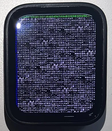
- This demo shows how to display a basic ASCII character table on the SH8601 display by using the Arduino GFX library on an ESP32. The core function of the code is to initialize the display and print ASCII characters in rows and columns according to the screen size
Hardware Connection
- Connect the development board to the computer
Code Analysis
-
Create data bus and graphic display objects
- Here a data bus object
busis created for communicating with the display, initialized with specific pin configurations. Then a graphics display objectgfxis created, passing parameters such as the data bus, reset pin, rotation angle, whether it is an IPS panel, and the width and height of the display
Arduino_DataBus *bus = new Arduino_ESP32QSPI(LCD_CS /* CS */, LCD_SCLK /* SCK */, LCD_SDIO0 /* SDIO0 */, LCD_SDIO1 /* SDIO1 */,LCD_SDIO2 /* SDIO2 */, LCD_SDIO3 /* SDIO3 */);Arduino_GFX *gfx = new Arduino_SH8601(bus, -1 /* RST */,0 /* rotation */, false /* IPS */, LCD_WIDTH, LCD_HEIGHT); - Here a data bus object
-
Draw row and column numbers and character table
- First set the text color to green and print the row numbers one by one on the display. Then set the text color to blue and print the column numbers. Next, use a loop to draw each character individually, forming the character table, with each character using white foreground and black background
gfx->setTextColor(GREEN);for (int x = 0; x < numRows; x++) {gfx->setCursor(10 + x * 8, 2);gfx->print(x, 16);}gfx->setTextColor(BLUE);for (int y = 0; y < numCols; y++) {gfx->setCursor(2, 12 + y * 10);gfx->print(y, 16);}char c = 0;for (int y = 0; y < numRows; y++) {for (int x = 0; x < numCols; x++) {gfx->drawChar(10 + x * 8, 12 + y * 10, c++, WHITE, BLACK);}}
Execution Result
04_GFX_FT3168_Image
Example Description
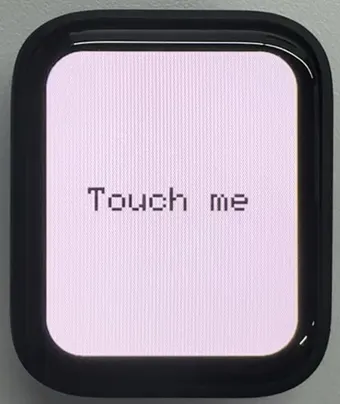
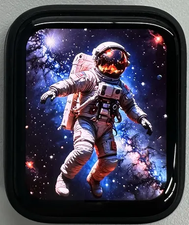
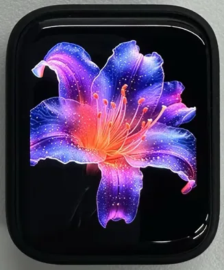
- This demo implements a touch screen display interface using the QSPI-driven SH8601 display on an ESP32-C6. It integrates an I2C touch controller (FT3168) for detecting touch input, as well as an I2C GPIO expander (TCA9554) for managing additional output pins. This code sets up the display screen, touch controller, and expander, and cycles through multiple images when the screen is touched
Hardware Connection
- Connect the development board to the computer
Code Analysis
-
Image display:
if (fingers_number > 0) {switch (Image_Flag) {case 0: gfx->draw16bitRGBBitmap(0, 0, (uint16_t *)gImage_1, LCD_WIDTH, LCD_HEIGHT); break;case 1: gfx->draw16bitRGBBitmap(0, 0, (uint16_t *)gImage_2, LCD_WIDTH, LCD_HEIGHT); break;case 2: gfx->draw16bitRGBBitmap(0, 0, (uint16_t *)gImage_3, LCD_WIDTH, LCD_HEIGHT); break;case 3: gfx->draw16bitRGBBitmap(0, 0, (uint16_t *)gImage_4, LCD_WIDTH, LCD_HEIGHT); break;case 4: gfx->draw16bitRGBBitmap(0, 0, (uint16_t *)gImage_5, LCD_WIDTH, LCD_HEIGHT); break;}Image_Flag++;if (Image_Flag > 4) {Image_Flag = 0;}}
Code Modification
- The image content resources are large. You need to set: Tools -> Partition Scheme -> 16M Flash (3MB APP/9.9MB FATFS)
Execution Result
 |  |  |
|---|
05_GFX_PCF85063_simpleTime
Example Description
- This demo demonstrates how to use the PCF85063 RTC module to display the current time on the SH8601 display. It retrieves the time every second and updates the display only when the time changes
Hardware Connection
- Connect the development board to the computer
Code Analysis
-
setup: Performs demo initialization settings
- Initializes the serial port to provide a channel for outputting error messages
- Initializes the real-time clock chip, including connection checks and setting the initial time to ensure time accuracy
- Initializes the graphics display device, sets the background color and brightness, providing a visual interface for time display
-
loop: Continuously checks for time changes and updates the time display on the screen during program execution
- Periodically checks if the time has changed by comparing the difference between the current time and the last updated time to determine if an update is needed
- Retrieves time information from the RTC and formats it for correct display on the screen
- If the time changes, clears the previous time display area, sets text color and size, calculates the centered position, and displays the new time on the screen. Finally saves the current time as the previous time for the next comparison
Execution Result

06_GFX_ESPWiFiAnalyzer
Example Description
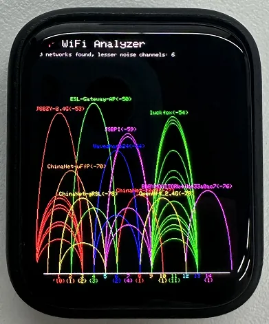
- This demo demonstrates drawing WiFi band signal strength on the SH8601 display, implementing the function of a WiFi analyzer
Hardware Connection
- Connect the development board to the computer
Code Analysis
-
setup: Prepares for the initialization of the entire program
- Initializes serial port communication, sets the baud rate to 115200 for outputting information and debugging
- Sets WiFi to station mode and disconnects, preparing for subsequent network scanning
- Performs some additional pre-initialization operations based on different hardware conditions (if GFX_EXTRA_PRE_INIT is defined)
- Initializes the graphic display device, calculates some display-related parameters such as text size, banner height, etc., and sets the display brightness. Finally draws the initial banner information
-
loop: Executes the main program logic, including performing WiFi network scanning, processing scan results, drawing charts and displaying statistical information, and performing power-saving operations as needed
- WiFi scanning and processing: Performs WiFi network scanning, obtains the number of networks and various network information; counts the number of access points per channel, calculates noise levels and determines signal peaks; draws WiFi signal strength charts based on scan results, including drawing ellipses representing signal strength and displaying related network information
- Displaying statistical information: Prints the number of networks found and information about channels with less noise on the display, draws chart baselines and channel markers, and displays the number of access points per channel
- Power-saving operations: Based on the configured number of scans, performs power-saving operations when conditions are met, such as turning off the display power pin and entering deep sleep mode
Execution Result
07_GFX_Clock
Example Description
- This demo demonstrates a simple SH8601 clock, implementing a clock example using simple marker pointers and time management
Hardware Connection
- Connect the development board to the computer
Code Analysis
-
Drawing hour, minute, and second hands:
void redraw_hands_cached_draw_and_erase() {gfx->startWrite();draw_and_erase_cached_line(center, center, nsx, nsy, SECOND_COLOR, cached_points, sHandLen + 1, false, false);draw_and_erase_cached_line(center, center, nhx, nhy, HOUR_COLOR, cached_points + ((sHandLen + 1) * 2), hHandLen + 1, true, false);draw_and_erase_cached_line(center, center, nmx, nmy, MINUTE_COLOR, cached_points + ((sHandLen + 1 + hHandLen + 1) * 2), mHandLen + 1, true, true);gfx->endWrite();}
Execution Result

08_LVGL_Animation
Example Description
- This demo demonstrates a simple LVGL slider example that can change the screen backlight brightness by adjusting the slider value
Hardware Connection
- Connect the development board to the computer
Code Analysis
-
Modify the backlight brightness in real time
int32_t slider_value = lv_slider_get_value(ui_Slider1);int32_t brightness = map(slider_value, 0, 100, 5, 255);gfx->Display_Brightness(brightness);
Execution Result

09_LVGL_change_background
Example Description
- This demo demonstrates an LVGL background brightness/darkness scene change, implementing background color changes by defining simple button components
Hardware Connection
- Connect the development board to the computer
Code Analysis
- setup: Responsible for the initialization of the entire system
- First, initializes the serial port for possible debugging output
- Then initializes the I2C bus and expansion chip, setting the pin modes and initial states of the expansion chip
- Continuously attempts to initialize the touch controller, setting its power mode upon success
- Initializes the graphics display device and sets brightness, also prints LVGL and Arduino version information
- Initializes LVGL, including registering a debug print callback function, initializing display driver and input device driver
- Creates and starts an LVGL timer, initializes the user interface and prints the setup completion message
- loop
- In the main loop, continuously calls lv_timer_handler() to let the LVGL graphics library handle various tasks
- Adds a small delay to avoid excessive CPU resource consumption
- my_touchpad_read: Reads the coordinates of the touchpad, sets the state of LVGL's input device based on touch status, and updates touch coordinates
Execution Result
 |  |
|---|
10_LVGL_PCF85063_simpleTime
Example Description
- This demo demonstrates using the PCF85063 RTC module to display the current time on the SH8601 display under LVGL. It retrieves the time every second and updates the display only when the time changes, resulting in better time refresh effects
Hardware Connection
- Connect the development board to the computer
Code Analysis
- setup: Responsible for initializing various hardware devices and the LVGL graphics library environment
- Serial initialization: USBSerial.begin(115200) prepares for serial debugging
- Real-time clock initialization: Attempts to initialize the real-time clock rtc. If it fails, enters an infinite loop. Set the date and time
- Touch controller initialization: Continuously attempts to initialize the touch controller FT3168. If initialization fails, prints an error message and waits with a delay; prints a success message upon success
- Graphics display initialization: Initializes the graphics display device gfx, sets brightness, and prints LVGL and Arduino version information Then initializes the LVGL, including registering a print callback function for debugging, initializing the display driver and the input device driver. Creates and starts an LVGL timer. Finally creates a label and sets its initial text to "Initializing..."
- loop
- lv_timer_handler(): This is an important function in the LVGL graphics library, used to handle various timer events, animation updates, input processing, and other tasks for the graphical interface. Calling this function in each loop ensures the graphical interface runs smoothly and responds to interactions promptly
- Time update and display: Gets the real-time clock time every second and prints it via the serial port. Then formats the time into a string and updates the text of the label to display the current time. Simultaneously sets the font of the label to a specific font. Finally adds a small delay
Execution Result

11_LVGL_QMI8658_ui
Example Description
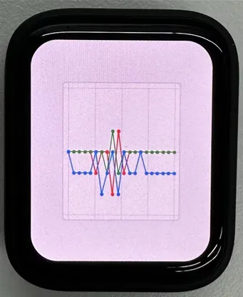
- This demo demonstrates using LVGL for graphical display, communicating with the QMI8658 IMU to obtain accelerometer and gyroscope data
Hardware Connection
- Connect the development board to the computer
Code Analysis
- setup: Responsible for initializing various hardware devices and the LVGL graphics library environment
- Serial initialization: USBSerial.begin(115200) prepares for serial debugging
- Touch controller initialization: Continuously attempts to initialize the touch controller FT3168. If initialization fails, prints an error message and waits with a delay; prints a success message upon success
- Graphics display initialization: Initializes the graphics display device gfx, sets brightness, and prints LVGL and Arduino version information Then initializes the LVGL, including registering a print callback function for debugging, initializing the display driver and the input device driver. Creates and starts an LVGL timer. Finally creates a label and sets its initial text to "Initializing..."
- Creating a chart: Creates a chart object chart, sets chart properties such as type, range, number of data points, etc., and adds data series for the three axes of acceleration
- Acceleration sensor initialization: Initializes the acceleration sensor qmi, configures accelerometer and gyroscope parameters, enables them, and prints the chip ID and control register information
- loop
- lv_timer_handler(): This is an important function in the LVGL graphics library, used to handle various timer events, animation updates, input processing, and other tasks for the graphical interface. Calling this function in each loop ensures the graphical interface runs smoothly and responds to interactions promptly
- Reading acceleration sensor data: If acceleration sensor data is ready, reads acceleration data and prints it via the serial port, while updating the chart to display acceleration data. If the gyroscope data is ready, reads the gyroscope data and prints it via the serial port. Finally adds a small delay to increase data polling frequency
Execution Result
12_LVGL_Widgets
Example Description
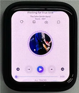
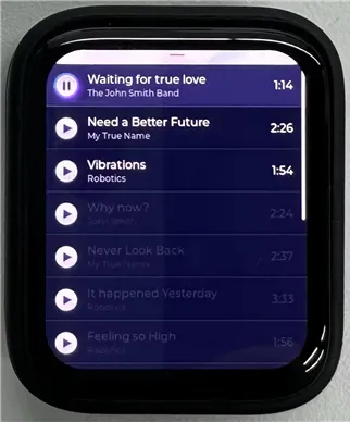
- This example demonstrates LVGL Widgets. The frame rate can reach 50~60 fps in dynamic states. Optimizing the SH8601 display library can achieve smoother frame rates. This can be compared with scenarios where double buffering and dual acceleration are enabled in the ESP-IDF environment
Hardware Connection
- Connect the development board to the computer
Code Analysis
- setup: Responsible for initializing various hardware devices and the LVGL graphics library environment
- Serial initialization: USBSerial.begin(115200) prepares for serial debugging
- I2C bus Initialization: Wire.begin(IIC_SDA, IIC_SCL); initializes I2C bus for communicating with other I2C devices
- Expansion chip initialization: Creates and initializes the expansion chip expander, sets pin modes to output, and performs some initial pin state settings
- Touch controller initialization: Continuously attempts to initialize the touch controller FT3168. If initialization fails, prints an error message and waits with a delay; prints a success message upon success
- Graphics display initialization: Initializes the graphics display device gfx, sets brightness, and obtains the width and height of the screen. Then initializes LVGL, including registering a print callback function for debugging, setting the touch controller's power mode to monitoring mode, initializing display driver and input device driver. Creates and starts an LVGL timer. Creates a label and sets its text. Finally calls lv_demo_widgets() to showcase LVGL example widgets
- loop
- lv_timer_handler(): This is an important function in the LVGL graphics library, used to handle various timer events, animation updates, input processing, and other tasks for the graphical interface. Calling this function in each loop ensures the graphical interface runs smoothly and responds to interactions promptly
- delay(5);: Adds a small delay to avoid excessive CPU resource consumption
Execution Result
 |  |
|---|
13_ES8311
Example Description
- This demo demonstrates using I2S to drive the ES8311 chip, playing the converted binary audio file
Hardware Connection
- Connect the development board to the computer
Code Analysis
- es8311_codec_init: Initializes the ES8311 audio codec.
- Creates an ES8311 codec handle es_handle
- Configures ES8311 clock parameters, including master clock and sampling clock frequencies, clock polarity, etc.
- Initializes the codec, sets audio resolution to 16-bit
- Configures sampling frequency
- Configures microphone-related parameters, such as turning off the microphone, setting volume and microphone gain
- setup: Performs overall initialization settings, including serial port, pins, I2S, and the ES8311 codec
- Initializesserial port for debugging output
- Sets a specific pin as output and pulls it high
- Configures the I2S bus, setting pins, operating mode, sample rate, data bit width, channel mode, etc.
- Initializes the I2C bus
- Calls the es8311_codec_init function to initialize the ES8311 codec
- Plays a pre-defined audio data (canon_pcm) via the I2S bus
Execution Result
- The device will play auido directly without showing content on the screen
14_LVGL_Sqprj
Example Description
- This demo demonstrates SquareLine UI combined with LVGL. It uses the QMI8658 sensor to achieve adaptive screen display orientation, displays real-time time via WiFi, and changes backlight brightness by detecting touch input in specific areas
Hardware Connection
- Connect the development board to the computer
Code Analysis
- setup
- Serial initialization
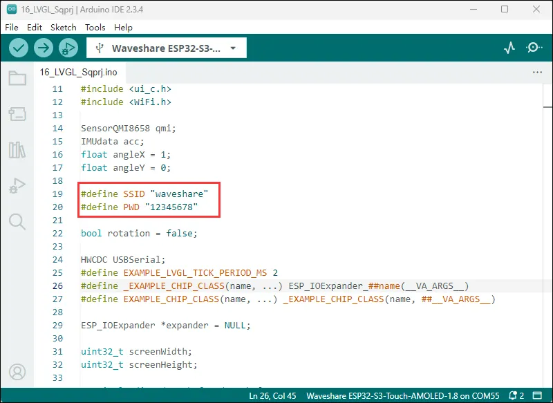
- Wi-Fi initialization: Wi-Fi connection and network time configuration
- I2C communication and expander initialization: Initializes I2C communication bus, specifies SDA and SCL pins, configures multiple pins (pins 0, 1, 2, 6) of the expander
- Sensor initialization: Initializes the QMI8658 sensor, initializes the touch controller (FT3168 object)
- Display initialization and related configuration
- loop()
- Interface rotation processing based on sensor data
- LVGL graphical interface update
- Display brightness adjustment processing
- Interface element value updates
Execution Result
- The image content resources are large. You need to set: Tools -> Partition Scheme -> 16M Flash (3MB APP/9.9MB FATFS)
- Modify to your available WiFi
Execution Result