Working with Arduino
This chapter contains the following sections. Please read as needed:
Arduino Getting Started
New to Arduino ESP32 development and looking for a quick start? We have prepared a comprehensive Getting Started Tutorial for you.
- Section 0: Getting to Know ESP32
- Section 1: Installing and Configuring Arduino IDE
- Section 2: Arduino Basics
- Section 3: Digital Output/Input
- Section 4: Analog Input
- Section 5: Pulse Width Modulation (PWM)
- Section 6: Serial Communication (UART)
- Section 7: I2C Communication
- Section 8: SPI Communication
- Section 9: Wi-Fi Basics
- Section 10: Web Server
- Section 11: Bluetooth
- Section 12: LVGL GUI Development
- Section 13: Comprehensive Project
Note: This tutorial uses the ESP32-S3-Zero as a reference example, and all hardware code is based on its pinout. Before you start, we recommend checking the pinout of your development board to ensure the pin configuration is correct.
Setting Up Development Environment
1. Installing and Configuring the Arduino IDE
Please refer to the tutorial Installing and Configuring Arduino IDE to download and install the Arduino IDE and add ESP32 support.
2. Installing the ESP32 Development Board
-
To use ESP32-related boards in the Arduino IDE, you must first install the board package "esp32 by Espressif Systems".
-
Install according to the Board Installation Requirements. "Online Installation" is generally recommended. If online installation fails, use "Offline Installation".
-
For the installation tutorial, please refer to Arduino Board Management Tutorial
-
Board installation instructions for the ESP32-C6-Touch-AMOLED-2.06
Board Name Installation Requirement Version Requirement esp32 by Espressif Systems "Offline Installation" / "Online Installation" ≥3.2.0
3. Installing Libraries
-
When installing Arduino libraries, there are generally two methods: Online Installation and Offline Installation. ** If the library installation requires offline installation, you must use the provided library files.**
-
For most libraries, users can easily search for and install them via the Arduino IDE's online Library Manager. However, some open-source or custom libraries are not synchronized to the Arduino Library Manager and therefore cannot be found through online search. In this case, users can only install these libraries manually via offline methods.
-
The library files for the ESP32-C6-Touch-AMOLED-2.06 are included in the example package. Click here to download: ESP32-C6-Touch-AMOLED-2.06 Example Package
-
For library installation tutorial, please refer to Arduino Library Manager Tutorial
-
ESP32-C6-Touch-AMOLED-2.06 library descriptions
Library or File Name Description Version Installation Method Arduino_DriveBus FT3168 touch controller driver library —— "Offline" Installation GFX_Library_for_Arduino GFX graphics library adapted for CO5300 v1.6.0 "Online" or "Offline" Installation lvgl LVGL graphics library v9.3.0 After "Online" installation, copy the demos folder to src; "Offline" installation is recommended SensorLib PCF85063, QMI8658 sensor driver library v0.3.1 "Online" or "Offline" Installation XPowersLib AXP2101 power management chip driver library v0.2.6 "Online" or "Offline" Installation Mylibrary Development board pin macro definitions -- "Offline" Installation lv_conf.h LVGL configuration file -- "Offline" Installation
There are strong dependencies between versions of LVGL and its driver libraries. For example, a driver written for LVGL v8 may not be compatible with LVGL v9. To ensure that the examples can be reproduced reliably, it is recommended to use the specific versions listed in the table above. Mixing different versions of libraries may lead to compilation failures or runtime errors.
Example
-
ESP32-C6-Touch-AMOLED-2.06 Example Programs
Example Basic Description Dependency Library 01_HelloWorld Demonstrates the basic graphics library function and can also be used to test the basic performance of display screens and the display effect of random text GFX_Library_for_Arduino 02_GFX_AsciiTable Prints ASCII characters in rows and columns on the screen according to the screen size GFX_Library_for_Arduino 03_LVGL_PCF85063_simpleTime LVGL library displays the current time LVGL, SensorLib 04_LVGL_QMI8658_ui LVGL draws an acceleration line chart LVGL, SensorLib 05_LVGL_AXP2101_ADC_Data Displays PMIC data with LVGL LVGL, XPowersLib 06_LVGL_Arduino_v9 LVGL example LVGL, Arduino_DriveBus
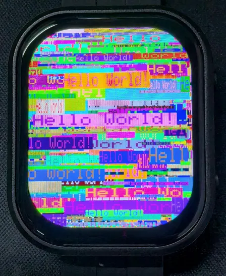
01_HelloWorld
Example Description
- This example demonstrates how to control the CO5300 display using the Arduino GFX library, demonstrating basic graphics library functions through dynamically changing text. This code can also be used to test the basic performance of the display and the random text display effects
Hardware Connection
- Connect the development board to the computer.
Code Analysis
-
Display initialization:
if (!gfx->begin()) {USBSerial.println("gfx->begin() failed!");} -
Clear the screen and display text:
gfx->fillScreen(BLACK);gfx->setCursor(10, 10);gfx->setTextColor(RED);gfx->println("Hello World!"); -
Animated display:
gfx->setCursor(random(gfx->width()), random(gfx->height()));gfx->setTextColor(random(0xffff), random(0xffff));gfx->setTextSize(random(6), random(6), random(2));gfx->println("Hello World!");
Operation Result
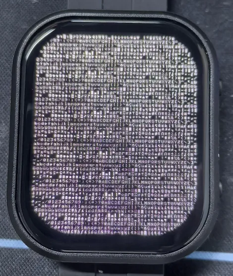
02_GFX_AsciiTable
Example Description
- This example shows how to display a basic ASCII character table on the CO5300 display by using the Arduino GFX library on an ESP32. The core function of the code is to initialize the display and print ASCII characters in rows and columns according to the screen size
Hardware Connection
- Connect the development board to the computer.
Code Analysis
-
Create data bus and graphic display objects
- Here a data bus object
busis created for communicating with the display, initialized with specific pin configurations. Then a graphics display objectgfxis created, passing parameters such as the data bus, reset pin, rotation angle, whether it is an IPS panel, and the width and height of the display
Arduino_DataBus *bus = new Arduino_ESP32QSPI(LCD_CS /* CS */, LCD_SCLK /* SCK */, LCD_SDIO0 /* SDIO0 */, LCD_SDIO1 /* SDIO1 */,LCD_SDIO2 /* SDIO2 */, LCD_SDIO3 /* SDIO3 */);Arduino_GFX *gfx = new Arduino_CO5300(bus, -1 /* RST */,0 /* rotation */, false /* IPS */, LCD_WIDTH, LCD_HEIGHT); - Here a data bus object
-
Draw row and column numbers and character table
- First set the text color to green and print the row numbers one by one on the display. Then set the text color to blue and print the column numbers. Next, use a loop to draw each character individually, forming the character table, with each character using white foreground and black background
gfx->setTextColor(GREEN);for (int x = 0; x < numRows; x++) {gfx->setCursor(10 + x * 8, 2);gfx->print(x, 16);}gfx->setTextColor(BLUE);for (int y = 0; y < numCols; y++) {gfx->setCursor(2, 12 + y * 10);gfx->print(y, 16);}char c = 0;for (int y = 0; y < numRows; y++) {for (int x = 0; x < numCols; x++) {gfx->drawChar(10 + x * 8, 12 + y * 10, c++, WHITE, BLACK);}}
Operation Result
03_LVGL_PCF85063_simpleTime
Example Description
- This example demonstrates using the PCF85063 RTC module to display the current time on the CO5300 display, retrieving the time every second and updating the display only when the time changes.
Hardware Connection
- Connect the development board to the computer.
Code Analysis
setup: Performs demo initialization settings- Initializes the serial port to provide a channel for outputting error messages
- Initializes the real-time clock chip, including connection checks and setting the initial time to ensure time accuracy
- Initializes the graphics display device, sets the background color and brightness, providing a visual interface for time display
loop: Continuously checks for time changes and updates the time display on the screen during program execution- Periodically checks if the time has changed by comparing the difference between the current time and the last updated time to determine if an update is needed
- Retrieves time information from the RTC and formats it for correct display on the screen
- If the time changes, clears the previous time display area, sets text color and size, calculates the centered position, and displays the new time on the screen. Finally saves the current time as the previous time for the next comparison
Operation Result

04_LVGL_QMI8658_ui
Example Description
- This example demonstrates using LVGL for graphical display, communicating with the QMI8658 IMU to obtain accelerometer and gyroscope data
Hardware Connection
- Connect the development board to the computer.
Code Analysis
setup: Responsible for initializing various hardware devices and the LVGL graphics library environment- Serial initialization:
USBSerial.begin(115200)prepares for serial debugging - Touch controller initialization: Continuously attempts to initialize the touch controller
FT3168. If initialization fails, prints an error message and waits with a delay; prints a success message upon success - Graphics display initialization: Initializes the graphics display device
gfx, sets brightness, and prints LVGL and Arduino version information. Then initializes the LVGL, including registering a print callback function for debugging, initializing the display driver and the input device driver. Creates and starts an LVGL timer. Finally creates a label and sets its initial text to "Initializing..." - Creating a chart: Creates a chart object
chart, sets chart properties such as type, range, number of data points, etc., and adds data series for the three axes of acceleration - Acceleration sensor initialization: Initializes the acceleration sensor
qmi, configures accelerometer and gyroscope parameters, enables them, and prints the chip ID and control register information
- Serial initialization:
looplv_timer_handler(): This is an important function in the LVGL graphics library, used to handle various timer events, animation updates, input processing, and other tasks for the graphical interface. Calling this function in each loop ensures the graphical interface runs smoothly and responds to interactions promptly- Reading acceleration sensor data: If acceleration sensor data is ready, reads acceleration data and prints it via the serial port, while updating the chart to display acceleration data. If the gyroscope data is ready, reads the gyroscope data and prints it via the serial port. Finally adds a small delay to increase data polling frequency
Operation Result
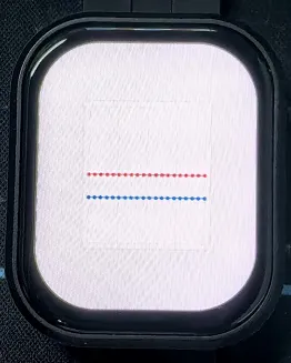
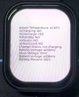
05_LVGL_AXP2101_ADC_Data
Example Description
- This example demonstrates power management using the XPowers library under LVGL, and provides PWR custom button control for screen on and off actions
Hardware Connection
- Connect the development board to the computer.
Code Analysis
-
Screen on/off function
void toggleBacklight() {USBSerial.println(backlight_on);if (backlight_on) {for (int i = 255; i >= 0; i--) {gfx->Display_Brightness(i);delay(3);}}else{for(int i = 0;i <= 255;i++){gfx->Display_Brightness(i);delay(3);}}backlight_on = !backlight_on;}
Operation Result
-
Displayed parameters: chip temperature, charging status, discharging status, standby status, Vbus connection, Vbus good status, charger status, battery voltage, Vbus voltage, system voltage, battery percentage.
06_LVGL_Arduino_v9
Example Description
- This example demonstrates the LVGL Widgets example, achieving a frame rate of 10–15 FPS in dynamic states.
Hardware Connection
- Connect the development board to the computer.
Code Analysis
setup: Responsible for initializing various hardware devices and the LVGL graphics library environment- Serial initialization:
USBSerial.begin(115200)prepares for serial debugging - I2C bus Initialization:
Wire.begin(IIC_SDA, IIC_SCL); initializes I2C bus for communicating with other I2C devices - Expansion chip initialization: Creates and initializes the expansion chip
expander, sets pin modes to output, and performs some initial pin state settings - Touch controller initialization: Continuously attempts to initialize the touch controller
FT3168. If initialization fails, prints an error message and waits with a delay; prints a success message upon success - Graphics display initialization: Initializes the graphics display device
gfx, sets brightness, and obtains the width and height of the screen. Then initializes LVGL, including registering a print callback function for debugging, setting the touch controller's power mode to monitoring mode, initializing display driver and input device driver. Creates and starts an LVGL timer. Creates a label and sets its text. Finally callslv_demo_widgets()to showcase LVGL example widgets
- Serial initialization:
looplv_timer_handler(): This is an important function in the LVGL graphics library, used to handle various timer events, animation updates, input processing, and other tasks for the graphical interface. Calling this function in each loop ensures the graphical interface runs smoothly and responds to interactions promptlydelay(5): Adds a small delay to avoid excessive CPU resource consumption
Operation Result