ESP-IDF
This chapter contains the following sections. Please read as needed:
ESP-IDF Getting Started
New to ESP32 ESP-IDF development and looking to get started quickly? We have prepared a general Getting Started Tutorial for you.
- Section 1: Environment Setup
- Section 2: Running Examples
- Section 3: Creating a Project
- Section 4: Using Components
- Section 5: Debugging
- Section 6: FreeRTOS
- Section 7: Peripherals
- Section 8: Wi-Fi Programming
- Section 9: BLE Programming
Please Note: This tutorial uses the ESP32-S3-Zero as a teaching example, and all hardware code is based on its pinout. Before you start, it is recommended that you check the pinout of your development board to ensure the pin configuration is correct.
Setting Up Development Environment
For the ESP32-C6-Touch-AMOLED-2.16 development board, development is based on ESP-IDF V5.5.2. It is recommended to use the same version for testing and development, as other versions may have compatibility issues.
The following guide uses Windows as an example, demonstrating development using VS Code + the ESP-IDF extension. macOS and Linux users should refer to the official documentation.
The screenshots in this section use ESP-IDF V5.5.2 as an example. When installing, please select the ESP-IDF version that matches your board's example.
Install the ESP-IDF Development Environment
-
Download the installation manager from the ESP-IDF Installation Manager page. This is Espressif's latest cross-platform installer. The following steps demonstrate how to use its offline installation feature.
Click the Offline Installer tab on the page, then select Windows as the operating system and the ESP-IDF version you need (the version shown in the screenshot is for reference only — choose the version that fits your actual needs).

After confirming your selection, click the download button. The browser will automatically download two files: the ESP-IDF Offline Package (.zst) and the ESP-IDF Installer (.exe).

Please wait for both files to finish downloading.
-
Once the download is complete, double-click to run the ESP-IDF Installer (eim-gui-windows-x64.exe).
The installer will automatically detect if the offline package exists in the same directory. Click Install from archive.

Next, select the installation path. We recommend using the default path. If you need to customize it, ensure the path does not contain Chinese characters or spaces. Click Start installation to proceed.

-
When you see the following screen, the ESP-IDF installation is successful.

-
We recommend installing the drivers as well. Click Finish installation, then select Install driver.

Install Visual Studio Code and the ESP-IDF Extension
-
Download and install Visual Studio Code.
-
During installation, it is recommended to check Add "Open with Code" action to Windows Explorer file context menu to facilitate opening project folders quickly.
-
In VS Code, click the Extensions icon
 in the Activity Bar on the side (or use the shortcut Ctrl + Shift + X) to open the Extensions view.
 -
Enter ESP-IDF in the search box, locate the ESP-IDF extension, and click Install.

-
For ESP-IDF extension versions ≥ 2.0, the extension will automatically detect and recognize the ESP-IDF environment installed in the previous steps, requiring no manual configuration.
Example
The ESP-IDF examples are located in the ESP-IDF directory of the example package.
| Demo | Basic Program Description | Dependency Library |
|---|---|---|
| 01_AXP2101_Test | Drive the AXP2101 power management chip to obtain relevant power information | - |
| 02_I2C_QMI8658 | Print raw attitude data from the QMI chip | - |
| 03_I2C_PCF85063 | Print real-time time from the RTC chip | - |
| 04_SD_Card | Load and display TF card information | - |
| 05_WIFI_STA | Set to STA mode, can connect to AP and obtain IP address | - |
| 06_WIFI_AP | Set to AP mode to obtain the IP address of the access device | - |
| 07_Audio_Test | Play the sound recorded by the microphone through the speaker | - |
| 08_LVGL_V8_Test | LVGL V8 demo | LVGL V8.* |
| 09_LVGL_V9_Test | LVGL V9 demo | LVGL V9.* |
| 10_FactoryProgram | Comprehensive demo | LVGL V9.* |
01_AXP2101_Test
Description
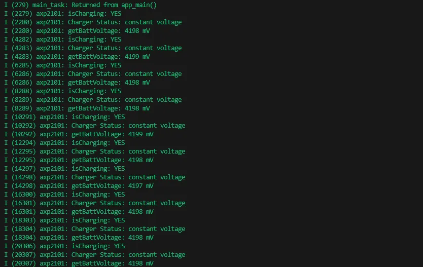
- Obtain power information by driving the AXP2101 and print it to the terminal.
Hardware Connection
- Connect the board to the computer using a USB cable
Code Analysis
axp2101.setDC1Voltage(3300);      //Set DCDC1 voltage to 3.3V
axp2101.setALDO1Voltage(3300);    //Set DCDC1 voltage to 3.3V
axp2101.setALDO2Voltage(3300);    //Set DCDC1 voltage to 3.3V
axp2101.setALDO3Voltage(3300);    //Set DCDC1 voltage to 3.3V
axp2101.setALDO4Voltage(3300);    //Set DCDC1 voltage to 3.3V
axp2101.setPrechargeCurr(XPOWERS_AXP2101_PRECHARGE_50MA);     //Set precharge current to 50mA
axp2101.setChargerConstantCurr(XPOWERS_AXP2101_CHG_CUR_500MA);  //Set constant charging current to 500mA
axp2101.setChargerTerminationCurr(XPOWERS_AXP2101_CHG_ITERM_50MA);  //Set termination charging current to 50mA
axp2101.getBattVoltage();   //Get lithium battery voltage
Operation Result
-
After compiling and downloading the program, open the Serial Monitor to see the printed power information, as shown in the figure below:
02_I2C_QMI8658
Description
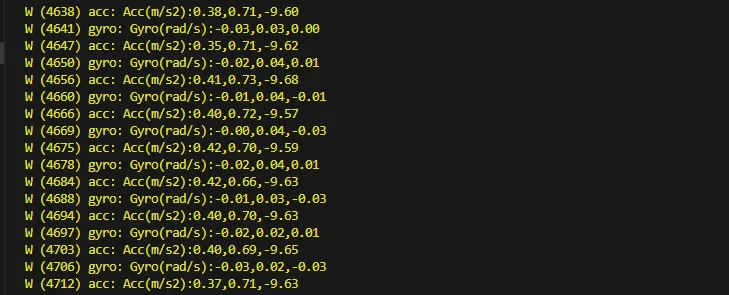
- Obtain attitude information by driving the QMI8658 and print it to the terminal.
Hardware Connection
- Connect the board to the computer using a USB cable
Code Analysis
qmi8658_set_accel_range(&qmi8658, QMI8658_ACCEL_RANGE_8G); // Set accelerometer range to ±8G (G = gravitational acceleration)
qmi8658_set_accel_odr(&qmi8658, QMI8658_ACCEL_ODR_1000HZ); // Set accelerometer output data rate to 1000Hz
qmi8658_set_gyro_range(&qmi8658, QMI8658_GYRO_RANGE_512DPS); // Set gyroscope range to ±512°/s
qmi8658_set_gyro_odr(&qmi8658, QMI8658_GYRO_ODR_1000HZ); // Set gyroscope output data rate to 1000Hz
qmi8658_set_accel_unit_mps2(&qmi8658, true); // Set accelerometer output unit to m/s²
qmi8658_set_gyro_unit_rads(&qmi8658, true); // Set gyroscope output unit to rad/s
qmi8658_set_display_precision(&qmi8658, 4); // Set output/print precision to 4 decimal places
Operation Result
-
After compiling and downloading the program, open the Serial Monitor to see the printed attitude information, as shown in the figure below:
03_I2C_QMI8658
Description
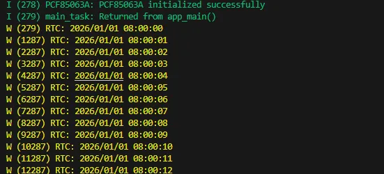
- Set and obtain time by driving the PCF85063, and print it to the terminal.
Hardware Connection
- Connect the board to the computer using a USB cable
Code Analysis
pcf85063a_datetime_t datatime = {
  .year = 2026,
  .month = 1,
  .day = 1,
  .hour = 8,
  .min = 0,
  .sec = 0
};
pcf85063a_set_time_date(&pcf85063, datatime);  /*Set start time 2026/1/1 08:00:00*/
pcf85063a_get_time_date(&pcf85063, &datatime);  /*Get current time*/
Operation Result
-
After the program is compiled and downloaded, open the serial port monitoring to see the RTC time of the printout, as shown in the following figure:
04_SD_Card
Description
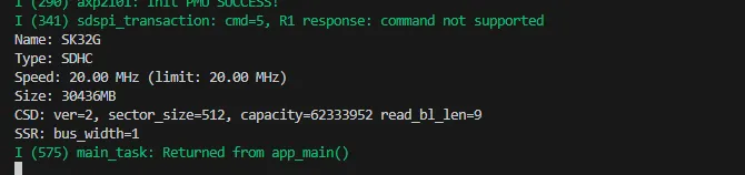
- Drive the TF card using SDSPI and print the TF card information to the terminal.
Hardware Connection
- Connect the board to the computer using a USB cable
Code Analysis
esp_vfs_fat_sdspi_mount(SdName_, &host, &slot_config, &mount_config, &sdCardHead);  //Mount sdcard to fatfs filesystem
int SDPort_WriteFile(const char *path, const void *data, size_t data_len);  //Write data to file
int SDPort_ReadFile(const char *path, uint8_t *buffer, size_t *outLen);  //Read data from file
int SDPort_ReadOffset(const char *path, void *buffer, size_t len, size_t offset);  //Read data from file with offset
int SDPort_WriteOffset(const char *path, const void *data, size_t len, bool append);  //Write data to file with offset
Operation Result
- After compiling and downloading the program, open the Serial Monitor to see the printed TF card information, as shown in the figure below:
05_WIFI_STA
Description
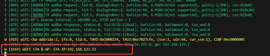
- Set the development board to Wi-Fi STA mode, connect to an AP router, and print the obtained IP address to the terminal.
Hardware Connection
- Connect the board to the computer using a USB cable
Code Analysis
nvs_flash_init();                                    // Initialize NVS (non-volatile storage) for saving Wi-Fi configuration data
esp_netif_init();                                    // Initialize TCP/IP stack, required for network communication
esp_event_loop_create_default();                     // Create default event loop for system event distribution (e.g., Wi-Fi events)
esp_netif_create_default_wifi_sta();                 // Create default Wi-Fi STA (Station) interface for connecting to a router
esp_netif_create_default_wifi_ap();                  // Create default Wi-Fi AP (Access Point) interface for providing a hotspot
strcpy((char*)sta_config.sta.ssid, "ESP32_STA");     // Set the router's SSID
strcpy((char*)sta_config.sta.password, "12345678");  // Set the router's password
esp_wifi_set_mode(WIFI_MODE_STA);                    // Set ESP32 Wi-Fi mode
Operation Result
- After compiling and downloading the program, open the Serial Monitor to see the printed IP address, as shown in the figure below:
06_WIFI_AP
Description
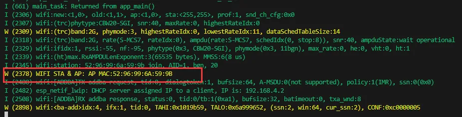
- Set the development board to Wi-Fi AP mode. Other STA devices can connect to this AP, and upon successful connection, the device's MAC address will be printed to the terminal.
Hardware Connection
- Connect the board to the computer using a USB cable
Code Analysis
nvs_flash_init();                                      // Initialize NVS (non-volatile storage) for saving Wi-Fi configuration data
esp_netif_init();                                      // Initialize TCP/IP stack, required for network communication
esp_event_loop_create_default();                       // Create default event loop for system event distribution (e.g., Wi-Fi events)
esp_netif_create_default_wifi_sta();                   // Create default Wi-Fi STA (Station) interface for connecting to a router
esp_netif_create_default_wifi_ap();                    // Create default Wi-Fi AP (Access Point) interface for providing a hotspot
strcpy((char*)ap_config.ap.ssid, "ESP32_AP");          // Set the AP's SSID to "ESP32_AP"
strcpy((char*)ap_config.ap.password, "12345678");      // et the AP's password to "12345678" (at least 8 characters)
ap_config.ap.max_connection = 4;                       // Set a maximum of 4 devices to connect simultaneously
ap_config.ap.authmode = WIFI_AUTH_WPA_WPA2_PSK;        // Set authentication mode to WPA/WPA2 PSK (password authentication)
esp_wifi_set_mode(WIFI_MODE_AP);                       // Set Wi-Fi mode to AP mode (hotspot only)
esp_wifi_set_config(WIFI_IF_AP, &ap_config);           // Apply the AP configuration to enable the Wi-Fi hotspot
Operation Result
- After compiling and downloading the program, open the Serial Monitor to see the printed MAC address, as shown in the figure below:
07_Audio_Test
Description
- Implement recording and playback by driving the ES8311 and ES7210 Codec chips.
Hardware Connection
- Connect the board to the computer using a USB cable
Code Analysis
esp_err_t play_pcm_from_spiffs(uint8_t *play_buf, const char *file_path,bool *Music_flag); // Read audio data from the spiffs filesystem and play it
void fac_play_read_storage(uint8_t *play_buf); // Read binary recording data from the filesystem and play it
void fac_rec_write_storage(uint8_t *rec_buf,size_t max_size); // Save recorded data to spiffs
Operation Result
-
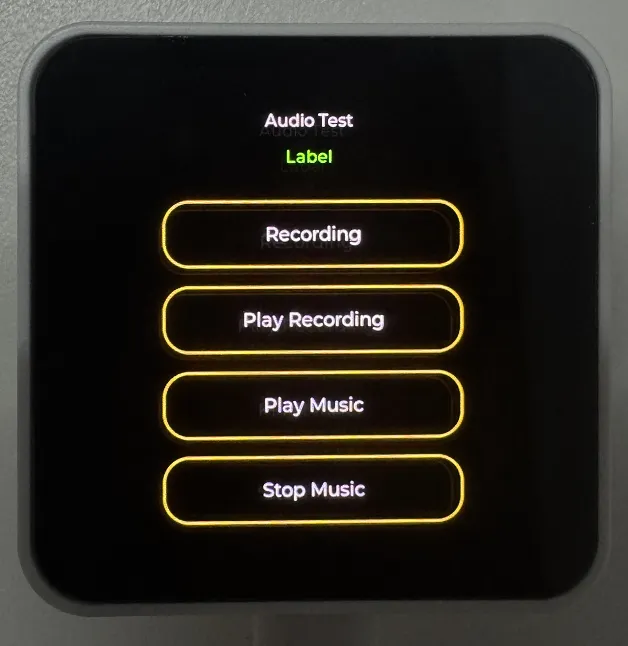
After compiling and downloading the program, the display on the development board will appear as shown below:
 tip
tip- Click Recording to record; recording lasts 3 seconds
- Click Play Recording to play the recording
- Click Play Music to play music
- Click Stop Music to pause music
08_LVGL_V8_Test
Description
- By porting LVGL V8, this helps users quickly get started with UI design.
Hardware Connection
- Connect the board to the computer using a USB cable
Code Analysis
#define Brightness_Test_EN  1 // Set to 0 to disable backlight test, default is 1
Custom_PmicPortInit(&user_i2cbus,0x34); // Initialize power IC
user_display = new DisplayPort(user_i2cbus,480,480); // Initialize the screen
user_display->DisplayPort_TouchInit(); // Initialize touch
Lvgl_PortInit(*user_display); // Initialize LVGL interface
Operation Result
- After compiling and downloading the program, the display on the development board will appear as shown below:

09_LVGL_V9_Test
Description
- By porting LVGL V9, this helps users quickly get started with UI design.
Hardware Connection
- Connect the board to the computer using a USB cable
Code Analysis
#define Brightness_Test_EN  1 // Set to 0 to disable backlight test, default is 1
Custom_PmicPortInit(&user_i2cbus,0x34); // Initialize power IC
user_display = new DisplayPort(user_i2cbus,480,480); // Initialize the screen
user_display->DisplayPort_TouchInit(); // Initialize touch
Lvgl_PortInit(*user_display); // Initialize LVGL interface
Operation Result
- After compiling and downloading the program, the display on the development board will appear as shown below:

10_FactoryProgram
Description
- Factory firmware. Users can flash the provided factory firmware to quickly get to know the development board.
Hardware Connection
- Connect the board to the computer using a USB cable
Operation Result
-
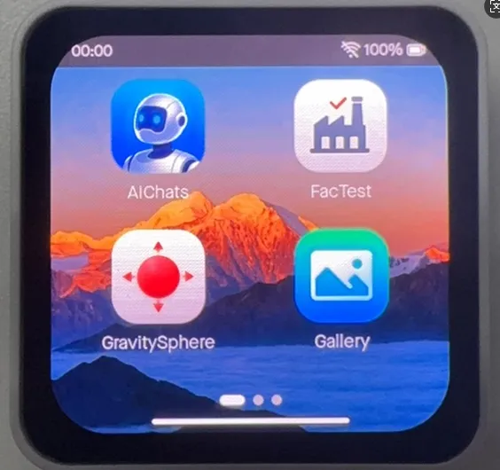
After flashing the factory firmware and restarting, the display on the development board will appear as shown below:
 tip
tip- AIChats app: XiaoZhi AI, can connect to large language models for voice conversation
- FacTest app: Test onboard hardware, helps users quickly identify issues
- GravitySphere app: Attitude ball implemented via IMU
- Gallery app: Gallery, can display images from TF card
- For more app development, follow the GitHub repository links; they will be continuously updated