Working with Arduino
This chapter includes the following sections. Please read as needed:
Arduino Getting Started
New to Arduino ESP32 development and looking for a quick start? We have prepared a comprehensive Getting Started Tutorial for you.
- Section 0: Getting to Know ESP32
- Section 1: Installing and Configuring Arduino IDE
- Section 2: Arduino Basics
- Section 3: Digital Output/Input
- Section 4: Analog Input
- Section 5: Pulse Width Modulation (PWM)
- Section 6: Serial Communication (UART)
- Section 7: I2C Communication
- Section 8: SPI Communication
- Section 9: Wi-Fi Basics
- Section 10: Web Server
- Section 11: Bluetooth
- Section 12: LVGL GUI Development
- Section 13: Comprehensive Project
Note: This tutorial uses the ESP32-S3-Zero as a reference example, and all hardware code is based on its pinout. Before you start, we recommend checking the pinout of your development board to ensure the pin configuration is correct.
Setting Up the Development Environment
1. Installing and Configuring the Arduino IDE
For the ESP32-C6-Touch-LCD-1.28 development board, Arduino IDE requires arduino-esp32 version v3.2.1 or later.
Please refer to the tutorial Install and Configure Arduino IDE to download and install the Arduino IDE and add ESP32 support.
2. Installing Libraries
- When installing Arduino libraries, there are typically two methods: online installation and offline installation. If the library installation requires offline installation, you must use the provided library files.
- For most libraries, users can easily search for and install them via the Arduino IDE's online Library Manager. However, some open-source or custom libraries are not synchronized to the Arduino Library Manager and therefore cannot be found through online search. In this case, users can only install these libraries manually via offline methods.
- The example package for the ESP32-C6-Touch-LCD-1.28 development board can be downloaded from here. The
Arduino\librariesdirectory within the package already contains all the library files required for this tutorial.
| Library/File Name | Description | Version | Installation Method |
|---|---|---|---|
| LVGL | Graphics Library | v8.4.0 | "Offline Installation" |
| Arduino_GFX_Library | Low-level graphics drawing library | v1.6.4 | "Offline/Online Installation" |
There are strong dependencies between versions of LVGL and its driver libraries. For example, a driver written for LVGL v8 may not be compatible with LVGL v9. To ensure that the examples can be reproduced reliably, it is recommended to use the specific versions listed in the table above. Mixing different versions of libraries may lead to compilation failures or runtime errors.
3. Arduino Project Settings

Example
The Arduino examples are located in the Arduino/examples directory of the example package.
| Example | Basic Program Description | Dependency Library |
|---|---|---|
| 01_I2C_PCF85063 | Read RTC time and print it | - |
| 02_I2C_QMI8658 | Print the raw data from the IMU | - |
| 03_SD_Card | Load and display TF card information | - |
| 04_WIFI_AP | Set to AP mode, can obtain the MAC address of connected devices | - |
| 05_WIFI_STA | Set to STA mode to connect to Wi-Fi and obtain an IP address | - |
| 06_HelloWorld_GFX | Display HelloWorld on the screen | GFX_Library_for_Arduino |
| 07_LVGL_Demo | LVGL example | LVGL |
01_I2C_PCF85063
Example Description
- This example demonstrates how the ESP32-C6-Touch-LCD-1.28 reads the time and date from the PCF85063 RTC and prints them to the terminal.
Expected Behavior
-
After compiling and uploading the program, open the serial monitor to see the printed RTC time, as shown below:

02_I2C_QMI8658
Example Description
- This example uses the I2C protocol to initialize the QMI8658 chip, then reads the corresponding attitude data and prints it to the terminal.
Expected Behavior
-
Open the serial monitor to view the raw data output from the IMU (Euler angles require conversion), as shown in the figure below:

03_SD_Card
Example Description
- This example drives the TF card via the SPI interface, mounts it, and prints the TF card information to the terminal.
Expected Behavior
-
Open the serial monitor to see the Size output, which is the actual capacity of the TF card, as shown below:

04_WIFI_AP
Example Description
- This example can set the development board as a hotspot, allowing phones or other devices in STA mode to connect to the development board.
Expected Behavior
-
After uploading the program, open the serial terminal. When a device successfully connects to the hotspot, the MAC address of that device is printed, as shown:

05_WIFI_STA
Example Description
- This example configures the development board as a STA device to connect to a router, thereby accessing the system network.
Expected Behavior
-
After uploading the program, open the serial terminal. When the device successfully connects to the router, it prints the assigned IP address, as shown:

06_HelloWorld_GFX
Example Description
- Implement some basic GUI interface on the screen by porting the Arduino_GFX_Library.
Expected Behavior
-
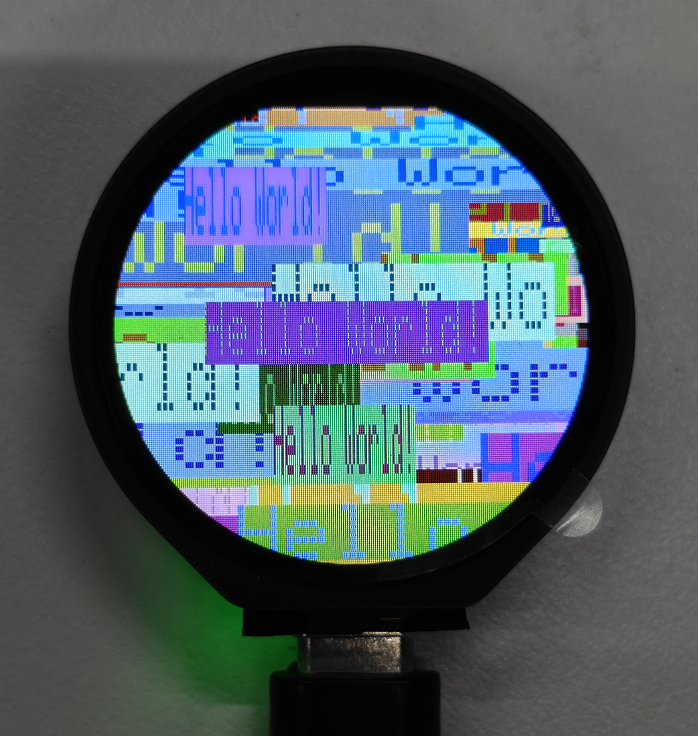
After flashing the program, you can see various "Hello World" formats displayed on the screen, as shown in the figure:
07_LVGL_Demo
Example Description
- This example ports LVGL V8 and runs an LVGL example program.
Expected Behavior
-
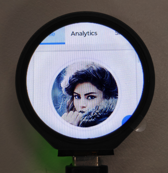
After the program is flashed, the device operation result is as follows: