ESP32-C6-Touch-LCD-1.47
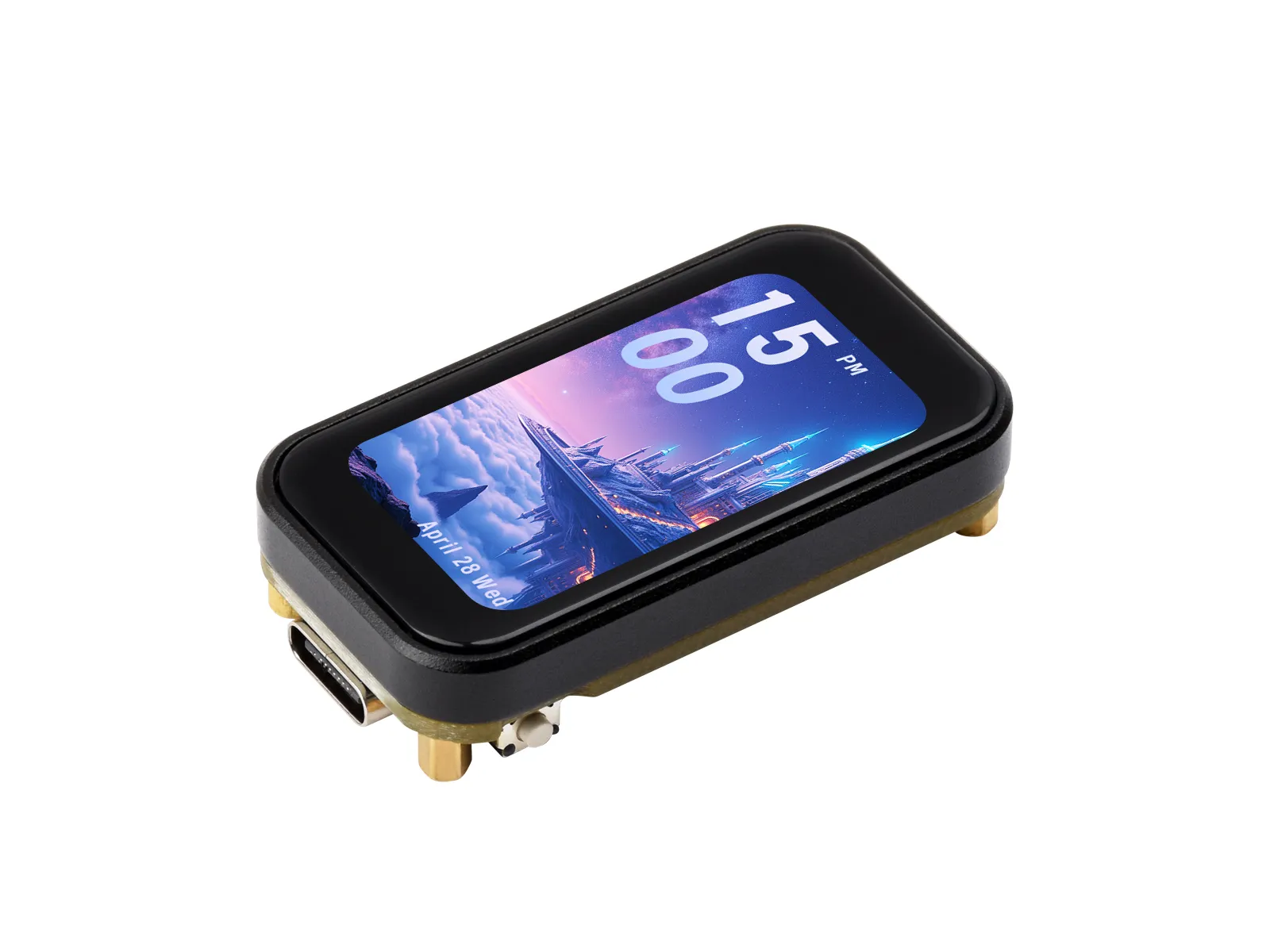
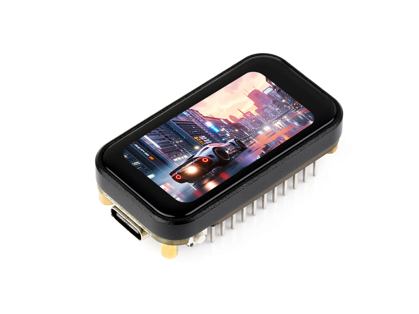
This product is a microcontroller development board based on the ESP32-C6FH8, supporting 2.4GHz Wi-Fi 6 and Bluetooth BLE 5. It features an integrated 8MB Flash and an onboard 1.47inch capacitive touch LCD screen, capable of smoothly running GUI programs such as LVGL. Combined with various peripheral interfaces, it enables rapid development of HMI and other applications for the ESP32-C6.
If you are looking for:
- Accelerate development with AI tools: Send this page link to an AI tool to help it understand the board hardware and generate usable code.
- Developing with Arduino IDE: See Working with Arduino
- Developing with ESP-IDF: See Working with ESP-IDF
- Downloading schematics, datasheets, and example code: See Related Resources
- Having issues: See Product FAQ or contact Technical Support
| SKU | Product |
|---|---|
| 31203 | ESP32-C6-Touch-LCD-1.47 |
| 31201 | ESP32-C6-Touch-LCD-1.47-M |
Features
- Equipped with a high-performance RISC-V 32-bit processor and a low-power RISC-V 32-bit processor; the high-performance processor clock is up to 160 MHz and the low-power processor clock is up to 20 MHz.
- Supports 2.4 GHz Wi-Fi 6 (802.11 ax/b/g/n) and Bluetooth 5 (BLE) wireless communication protocols, with an onboard antenna.
- Onboard 320KB ROM, 512KB HP SRAM, 16KB LP SRAM, and 8MB Flash
- Onboard 1.47inch capacitive touch LCD screen with 172 × 320 resolution and 262K colors
- Most GPIOs are brought out, supporting full-speed USB
- Onboard TF card slot for external TF card storage of images or files
- Supports flexible clock, multiple power modes, and other precise controls to enable low-power operation in various scenarios.
Onboard Resources

- ESP32-C6FH8 Dual RISC-V processor architecture, high-performance processor up to 160MHz, low-power processor up to 20MHz
- 8MB Flash Onboard 320KB ROM, 512KB high-performance SRAM, and 16KB low-power SRAM
- 2.4GHz Wi-Fi 6 and Bluetooth 5 (BLE) Supports 802.11 ax/b/g/n, onboard ceramic antenna
- 1.47inch IPS LCD, 172 × 320 resolution, 262K colors, display driver chip JD9853
- Capacitive Touch Touch controller AXS5106L, using I2C interface
- QMI8658A 6-axis IMU Includes 3-axis accelerometer and 3-axis gyroscope
- TF card Slot Connected via SPI interface for storing images or files
- ETA6098 Battery Charging/Power Management Circuit Supports battery connection; works with ME6217C33M5G to provide 3.3V power
- VBAT Pin Can be used to connect the battery positive terminal, with battery negative connected to
GND; do not connectVBATto3V3orVBUS - USB Type-C Interface Supports USB full-speed standard for power supply, programming, and USB communication
- RESET Button Connected to chip reset signal
ESP_RST - BOOT Button Connected to chip boot mode control signal, default using
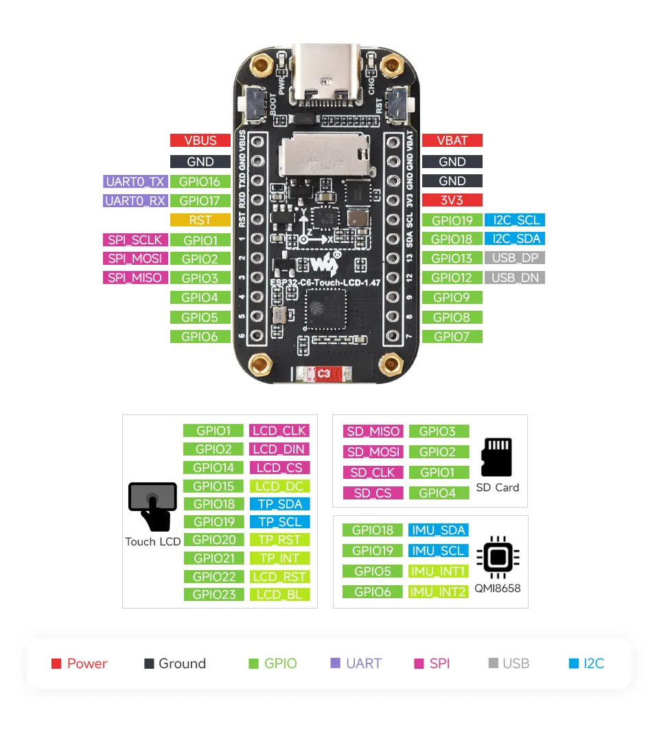
GPIO8 - 22Pin Header Interface Breaks out power, BAT, USB, UART, I2C, ADC, and multiple GPIOs
Peripheral Quick Reference
| Peripheral | Device / Function | Interface | Main Pins | Description |
|---|---|---|---|---|
| Main Controller | ESP32-C6FH8 | - | - | Dual RISC-V processors, up to 160MHz, onboard 8MB Flash |
| Display | 1.47inch IPS LCD, JD9853 | 4-wire SPI | GPIO1/2/14/15/22/23 | Resolution 172 × 320; GPIO1/2 are SPI clock and data, GPIO23 controls backlight |
| Touch | AXS5106L | I2C + INT + RST | GPIO18/19/20/21 | GPIO18=SDA, GPIO19=SCL, GPIO20=TP_RST, GPIO21=TP_INT |
| IMU | QMI8658A | I2C + INT | GPIO18/19/5/6 | Shares I2C with touch; GPIO5=IMU_INT1, GPIO6=IMU_INT2 |
| TF | TF card slot | SPI | GPIO1/2/3/4 | Shares SCK/MOSI with LCD; GPIO3=MISO, GPIO4=CS |
| I2C Bus | Onboard shared I2C | I2C | GPIO19=SCL, GPIO18=SDA | Connects to onboard devices such as AXS5106L and QMI8658A |
| USB | USB D-/D+ | USB Full Speed | GPIO12/13 | GPIO12=USB_N/D-, GPIO13=USB_P/D+ |
| UART | UART0 | UART | GPIO16/17 | GPIO16=ESP_TXD, GPIO17=ESP_RXD |
| Battery ADC | Battery voltage ADC | ADC | GPIO0 | Samples battery voltage via onboard voltage divider; network name BAT_ADC, R21 pull-up 200K, R22 pull-down 100K; VBAT = VADC × 3 |
| Power Management | ETA6098 + ME6217C33M5G | Power | VBUS/VBAT/3V3 | Handles battery charging, system power supply, and 3.3V regulation |
| Buttons | RESET, BOOT | GPIO / Reset | ESP_RST/GPIO8 | GPIO8 is boot mode control pin; use with caution when multiplexing |
Pinout Definition
GPIO Pin Assignments
| GPIO | Function | Connected to / Remarks |
|---|---|---|
GPIO0 | BAT_ADC | Battery voltage ADC sampling |
GPIO1 | LCD SCK / TF SCK | Shared SPI clock for LCD and TF |
GPIO2 | LCD MOSI / TF MOSI | Shared SPI data output for LCD LCD_SDA and TF CMD |
GPIO3 | TF MISO | TF D0 data input |
GPIO4 | TF CS | TF D3/CS chip select |
GPIO5 | IMU_INT1 | QMI8658A interrupt 1; consider onboard interrupt connection when using as general-purpose GPIO |
GPIO6 | IMU_INT2 | QMI8658A interrupt 2; consider onboard interrupt connection when using as general-purpose GPIO |
GPIO7 | IO7 | Broken out to header, not connected to major onboard peripherals |
GPIO8 | BOOT | Chip boot mode control pin, default connected to BOOT button |
GPIO12 | USB_N | USB D-; do not use as general-purpose GPIO when using USB functionality |
GPIO13 | USB_P | USB D+; do not use as general-purpose GPIO when using USB functionality |
GPIO14 | LCD_CS | LCD SPI chip select |
GPIO15 | LCD_DC | LCD data/command selection |
GPIO16 | ESP_TXD | UART0 TX |
GPIO17 | ESP_RXD | UART0 RX |
GPIO18 | ESP_SDA / TP_SDA | Onboard shared I2C SDA |
GPIO19 | ESP_SCL / TP_SCL | Onboard shared I2C SCL |
GPIO20 | TP_RST | AXS5106L touch reset |
GPIO21 | TP_INT | AXS5106L touch interrupt |
GPIO22 | LCD_RST | LCD reset |
GPIO23 | LCD_BL / LEDK | LCD backlight control |
LCD and Touch Pins
| Signal | GPIO | Description |
|---|---|---|
LCD_SCL | GPIO1 | LCD SPI clock, also denoted as SCK |
LCD_SDA | GPIO2 | LCD SPI data, also denoted as MOSI |
LCD_CS | GPIO14 | LCD chip select |
LCD_DC | GPIO15 | LCD data/command selection |
LCD_RST | GPIO22 | LCD reset |
LCD_BL / LEDK | GPIO23 | LCD backlight control |
TP_SCL | GPIO19 | Touch I2C SCL |
TP_SDA | GPIO18 | Touch I2C SDA |
TP_RST | GPIO20 | Touch reset |
TP_INT | GPIO21 | Touch interrupt |
TF Pins
| Signal | GPIO | Description |
|---|---|---|
SD_SCK / SD_CLK | GPIO1 | TF SPI clock, shared with LCD |
SD_MOSI / SD_CMD | GPIO2 | TF SPI command/data output, shared with LCD |
SD_MISO / SD_D0 | GPIO3 | TF data input |
SD_CS / SD_D3 | GPIO4 | TF chip select |
IMU and I2C Pins
| Device / Signal | GPIO | Description |
|---|---|---|
ESP_SCL | GPIO19 | Onboard shared I2C clock |
ESP_SDA | GPIO18 | Onboard shared I2C data |
IMU_INT1 | GPIO5 | QMI8658A interrupt 1 |
IMU_INT2 | GPIO6 | QMI8658A interrupt 2 |
The onboard I2C addresses listed in the FAQ include 0x51, 0x6B, and 0x7E. During development, confirm specific device addresses by referring to driver configurations and I2C scanning results.
USB, UART, and Buttons
| Signal | GPIO / Signal | Description |
|---|---|---|
USB_N | GPIO12 | USB D- |
USB_P | GPIO13 | USB D+ |
ESP_TXD | GPIO16 | UART0 TX |
ESP_RXD | GPIO17 | UART0 RX |
BAT_ADC | GPIO0 | Battery voltage ADC sampling |
RESET | ESP_RST | Chip reset signal, not a general-purpose GPIO |
BOOT | GPIO8 | Boot mode control button |
Precautions
GPIO1andGPIO2are shared SPI clock/data lines between the LCD and TF. When using the TF card or LCD, ensure proper control of their respective chip select signals.GPIO18andGPIO19are the onboard shared I2C bus, already connected to touch and IMU devices. When connecting external I2C devices, be mindful of address conflicts, pull-up resistors, and bus voltage levels.GPIO8is the chip boot mode control pin. The official FAQ suggests: if the program occupies this pin and prevents programming, temporarily connectGPIO8to3V3and re-enter download mode.GPIO12andGPIO13are USB D-/D+; do not use them as general-purpose GPIO when using USB functionality.GPIO16andGPIO17are connected to UART0, typically used for serial communication or debug output.GPIO0is connected to the battery voltage sampling circuit; when reusing as a general-purpose ADC/GPIO, consider the impact of the voltage divider network on the signal level.GPIO5andGPIO6are connected to QMI8658A interrupt outputs; consider IMU interrupt configuration when reusing these pins.- Before connecting a battery, verify the battery polarity and type. Do not connect
VBATdirectly to3V3orUSB VBUS. - TF cards should be formatted as FAT32. When the LCD and TF share the SPI bus, keep the chip select of the inactive device in an inactive state.
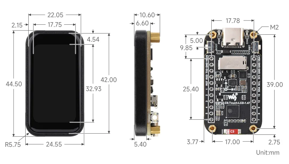
Dimensions

Development Methods
The ESP32-C6-Touch-LCD-1.47 supports both the Arduino IDE and ESP-IDF development frameworks, giving developers flexible options. You can choose the development tool that best suits your project needs and personal preferences.
Arduino generally offers a gentler learning curve and may be more approachable for beginners and hobbyists. ESP-IDF provides advanced tooling and finer control over system behavior, making it better suited to complex projects and applications with demanding performance requirements.
-
Arduino IDE is a convenient, flexible, and easy-to-use open-source electronics prototyping platform. It requires minimal foundational knowledge, allowing for rapid development after a short learning period. Arduino has a huge global user community, providing a vast amount of open-source code, project examples, and tutorials, as well as a rich library ecosystem that encapsulates complex functions, enabling developers to implement various features rapidly. You can refer to the Working with Arduino to complete the initial setup, and the tutorial also provides related example programs for reference.
-
ESP-IDF, short for Espressif IoT Development Framework, is a professional development framework launched by Espressif Systems for its ESP series of chips. It is based on C language development and includes compilers, debuggers, flashing tools, etc. It supports development via command line or integrated development environments (such as Visual Studio Code with the Espressif IDF plugin), which provides features like code navigation, project management, and debugging. We recommend using VS Code for development. For the specific configuration process, please refer to the Working with ESP-IDF. The tutorial also provides relevant example programs for reference.