Working with Arduino
This chapter contains the following sections. Please read as needed:
Arduino Getting Started
New to Arduino ESP32 development and looking for a quick start? We have prepared a comprehensive Getting Started Tutorial for you.
- Section 0: Getting to Know ESP32
- Section 1: Installing and Configuring Arduino IDE
- Section 2: Arduino Basics
- Section 3: Digital Output/Input
- Section 4: Analog Input
- Section 5: Pulse Width Modulation (PWM)
- Section 6: Serial Communication (UART)
- Section 7: I2C Communication
- Section 8: SPI Communication
- Section 9: Wi-Fi Basics
- Section 10: Web Server
- Section 11: Bluetooth
- Section 12: LVGL GUI Development
- Section 13: Comprehensive Project
Note: This tutorial uses the ESP32-S3-Zero as a reference example, and all hardware code is based on its pinout. Before you start, we recommend checking the pinout of your development board to ensure the pin configuration is correct.
Setting Up the Development Environment
1. Installing and Configuring the Arduino IDE
Please refer to the tutorial Installing and Configuring Arduino IDE to download and install the Arduino IDE and add ESP32 support.
2. Installing Libraries
To run the example, you need to install the corresponding library. The example code uses the GFX Library for Arduino library to drive the ST7789 display
and the Arduino_DriveBus library to drive the CST816 touch controller.
You can click this link to download the example package for the ESP32-C6-Touch-LCD-1.83 board from the Arduino directory. The Arduino\libraries directory within this package contains all the necessary library files required for this tutorial.
| Library or File Name | Description | Version | Installation Method |
|---|---|---|---|
| GFX Library for Arduino | ST7789 display driver graphics library | v1.6.0 | Install via library manager or manually |
| SensorLib | PCF85063, QMI8658 sensor driver library | v0.3.1 | Install via library manager or manually |
| XPowersLib | AXP2101 driver library | v0.3.0 | Install via library manager or manually |
| lvgl | LVGL display framework | v8.4.0 | Install via library manager or manually |
| Arduino_DriveBus | I2C, touch driver library | v1.0.1 | Install manually |
There are strong dependencies between versions of LVGL and its driver libraries. For example, a driver written for LVGL v8 may not be compatible with LVGL v9. To ensure that the examples can be reproduced reliably, it is recommended to use the specific versions listed in the table above. Mixing different versions of libraries may lead to compilation failures or runtime errors.
Installation Steps:
-
Download the example package.
-
Copy all folders (Arduino_DriveBus, GFX_Library_for_Arduino, etc.) in the
Arduino\librariesdirectory to the Arduino library folder.infoThe path to the Arduino libraries folder is typically:
c:\Users\<username>\Documents\Arduino\libraries.You can also locate it in the Arduino IDE by going to File > Preferences and checking the "Sketchbook location". The libraries folder is the
librariessubfolder within this path. -
For other installation methods, please refer to: Arduino Library Management Tutorial.
3. Additional Tips
You need to select and configure the development board for ESP32-C6-Touch-LCD-1.83.
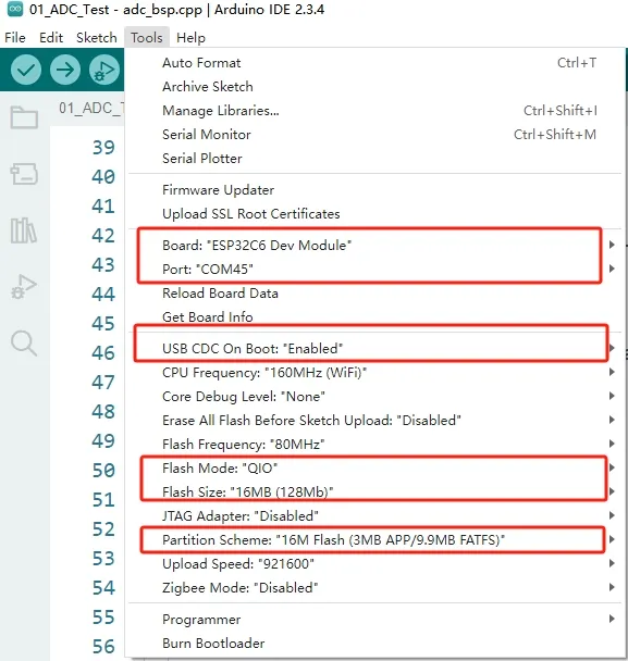
- The ESP32-C6-Touch-LCD-1.83 requires selecting ESP32S3 Dev Module.
- Select the USB port.
- The ESP32-C6-Touch-LCD-1.83 uses the ESP32-C6 native USB interface, not UART-to-USB. For serial communication:
-
The
printf()function can be used directly; -
To use the
Serial.println()function, additional configuration is required: Enable the "USB CDC On Boot" option in the IDE's Tools menu, or declare anHWCDCobject in your code to handle USB serial communication.
-
- Select 16MB Flash
- Select a Partition Table of the appropriate size
Example
The Arduino examples are located in the Arduino/examples directory of the example package.
| Example | Basic Description | Dependency Library |
|---|---|---|
| 01_sd_test | Demonstrates basic TF card mounting process, file read/write test | |
| 02_audio_out | Play MP3 audio | |
| 03_axp2101_example | Power management chip AXP2101 test | XPowersLib |
| 04_qmi8658_example | IMU QMI8658 test | SensorLib |
| 05_pcf85063_example | RTC real-time clock PCF85063 test | SensorLib |
| 06_gfx_helloworld | A simple ST7789 screen driver example | GFX_Library_for_Arduino |
| 07_LVGL_Arduino | LVGL v8.4 example program | Arduino_DriveBus, GFX_Library_for_Arduino, lvgl |
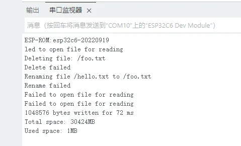
01_sd_test
This example demonstrates how to use SPI to mount a TF card and test file read/write operations
Code
01_sd_test.ino
#include "FS.h"
#include "SD.h"
#include "SPI.h"


#define REASSIGN_PINS
int sck = 1;
int miso = 16;
int mosi = 2;
int cs = 17;

void listDir(fs::FS &fs, const char *dirname, uint8_t levels) {
  Serial.printf("Listing directory: %s\n", dirname);

  File root = fs.open(dirname);
  if (!root) {
    Serial.println("Failed to open directory");
    return;
  }
  if (!root.isDirectory()) {
    Serial.println("Not a directory");
    return;
  }

  File file = root.openNextFile();
  while (file) {
    if (file.isDirectory()) {
      Serial.print("  DIR : ");
      Serial.println(file.name());
      if (levels) {
        listDir(fs, file.path(), levels - 1);
      }
    }else{
      Serial.print("  FILE: ");
      Serial.print(file.name());
      Serial.print("  SIZE: ");
      Serial.println(file.size());
    }
    file = root.openNextFile();
  }
}

void createDir(fs::FS &fs, const char *path) {
  Serial.printf("Creating Dir: %s\n", path);
  if (fs.mkdir(path)) {
    Serial.println("Dir created");
  }else{
    Serial.println("mkdir failed");
  }
}

void removeDir(fs::FS &fs, const char *path) {
  Serial.printf("Removing Dir: %s\n", path);
  if (fs.rmdir(path)) {
    Serial.println("Dir removed");
  }else{
    Serial.println("rmdir failed");
  }
}

void readFile(fs::FS &fs, const char *path) {
  Serial.printf("Reading file: %s\n", path);

  File file = fs.open(path);
  if (!file) {
    Serial.println("Failed to open file for reading");
    return;
  }

  Serial.print("Read from file: ");
  while (file.available()) {
    Serial.write(file.read());
  }
  file.close();
}

void writeFile(fs::FS &fs, const char *path, const char *message) {
  Serial.printf("Writing file: %s\n", path);

  File file = fs.open(path, FILE_WRITE);
  if (!file) {
    Serial.println("Failed to open file for writing");
    return;
  }
  if (file.print(message)) {
    Serial.println("File written");
  }else{
    Serial.println("Write failed");
  }
  file.close();
}

void appendFile(fs::FS &fs, const char *path, const char *message) {
  Serial.printf("Appending to file: %s\n", path);

  File file = fs.open(path, FILE_APPEND);
  if (!file) {
    Serial.println("Failed to open file for appending");
    return;
  }
  if (file.print(message)) {
    Serial.println("Message appended");
  }else{
    Serial.println("Append failed");
  }
  file.close();
}

void renameFile(fs::FS &fs, const char *path1, const char *path2) {
  Serial.printf("Renaming file %s to %s\n", path1, path2);
  if (fs.rename(path1, path2)) {
    Serial.println("File renamed");
  }else{
    Serial.println("Rename failed");
  }
}

deleteFile(fs::FS &fs, const char *path) {
  Serial.printf("Deleting file: %s\n", path);
  if (fs.remove(path)) {
    Serial.println("File deleted");
  }else{
    Serial.println("Delete failed");
  }
}

void testFileIO(fs::FS &fs, const char *path) {
  File file = fs.open(path);
  static uint8_t buf[512];
  size_t len = 0;
  uint32_t start = millis();
  uint32_t end = start;
  if (file) {
    len = file.size();
    size_t flen = len;
    start = millis();
    while (len) {
      size_t toRead = len;
      if (toRead > 512) {
        toRead = 512;
      }
      file.read(buf, toRead);
      len -= toRead;
    }
    end = millis() - start;
    Serial.printf("%u bytes read for %lu ms\n", flen, end);
    file.close();
  }else{
    Serial.println("Failed to open file for reading");
  }

  file = fs.open(path, FILE_WRITE);
  if (!file) {
    Serial.println("Failed to open file for writing");
    return;
  }

  size_t i;
  start = millis();
  for (i = 0; i < 2048; i++) {
    file.write(buf, 512);
  }
  end = millis() - start;
  Serial.printf("%u bytes written for %lu ms\n", 2048 * 512, end);
  file.close();
}

void setup() {
  Serial.begin(115200);

#ifdef REASSIGN_PINS
  SPI.begin(sck, miso, mosi, cs);
  if (!SD.begin(cs)) {
#else
  if (!SD.begin()) {
#endif
    Serial.println("Card Mount Failed");
    return;
  }
  uint8_t cardType = SD.cardType();

  if (cardType == CARD_NONE) {
    Serial.println("No TF card attached");
    return;
  }

  Serial.print("TF Card Type: ");
  if (cardType == CARD_MMC) {
    Serial.println("MMC");
  } else if (cardType == CARD_SD) {
    Serial.println("SDSC");
  } else if (cardType == CARD_SDHC) {
    Serial.println("SDHC");
  }else{
    Serial.println("UNKNOWN");
  }

  uint64_t cardSize = SD.cardSize() / (1024 * 1024);
  Serial.printf("TF Card Size: %lluMB\n", cardSize);

  listDir(SD, "/", 0);
  createDir(SD, "/mydir");
  listDir(SD, "/", 0);
  removeDir(SD, "/mydir");
  listDir(SD, "/", 2);
  writeFile(SD, "/hello.txt", "Hello ");
  appendFile(SD, "/hello.txt", "World!\n");
  readFile(SD, "/hello.txt");
  deleteFile(SD, "/foo.txt");
  renameFile(SD, "/hello.txt", "/foo.txt");
  readFile(SD, "/foo.txt");
  testFileIO(SD, "/test.txt");
  Serial.printf("Total space: %lluMB\n", SD.totalBytes() / (1024 * 1024));
  Serial.printf("Used space: %lluMB\n", SD.usedBytes() / (1024 * 1024));
}

void loop() {}
Code Analysis
-
Initialize SPI and mount the TF card:
#ifdef REASSIGN_PINSSPI.begin(sck, miso, mosi, cs);if (!SD.begin(cs)) {#elseif (!SD.begin()) {#endifSerial.println("Card Mount Failed");return;}uint8_t cardType = SD.cardType();if (cardType == CARD_NONE) {Serial.println("No TF card attached");return;}Serial.print("TF Card Type: ");if (cardType == CARD_MMC) {Serial.println("MMC");} else if (cardType == CARD_SD) {Serial.println("SDSC");} else if (cardType == CARD_SDHC) {Serial.println("SDHC");}else{Serial.println("UNKNOWN");}uint64_t cardSize = SD.cardSize() / (1024 * 1024);Serial.printf("TF Card Size: %lluMB\n", cardSize); -
Test file read/write:
listDir(SD, "/", 0);createDir(SD, "/mydir");listDir(SD, "/", 0);removeDir(SD, "/mydir");listDir(SD, "/", 2);writeFile(SD, "/hello.txt", "Hello ");appendFile(SD, "/hello.txt", "World!\n");readFile(SD, "/hello.txt");deleteFile(SD, "/foo.txt");renameFile(SD, "/hello.txt", "/foo.txt");readFile(SD, "/foo.txt");testFileIO(SD, "/test.txt");Serial.printf("Total space: %lluMB\n", SD.totalBytes() / (1024 * 1024));Serial.printf("Used space: %lluMB\n", SD.usedBytes() / (1024 * 1024));
02_audio_out
This example demonstrates how to play audio using I2S. It has no display on the screen, and will automatically play audio after flashing
Code
02_audio_out.ino
#include <Arduino.h>
#include "ESP_I2S.h"

#include "esp_check.h"

#include "Wire.h"
#include "es8311.h"

#include "music.h"

#define I2C_SDA 7
#define I2C_SCL 8

#define I2S_NUM I2S_NUM_0
#define I2S_MCK_PIN 19
#define I2S_BCK_PIN 20
#define I2S_LRCK_PIN 22
#define I2S_DOUT_PIN 23
#define I2S_DIN_PIN 21
#define PA_CTRL_PIN 0

#define EXAMPLE_SAMPLE_RATE (24000)
#define EXAMPLE_MCLK_MULTIPLE (256)  // If not using 24-bit data width, 256 should be enough
#define EXAMPLE_MCLK_FREQ_HZ (EXAMPLE_SAMPLE_RATE * EXAMPLE_MCLK_MULTIPLE)
#define EXAMPLE_VOICE_VOLUME (50)

I2SClass i2s;

void setupI2S() {
  i2s.setPins(I2S_BCK_PIN, I2S_LRCK_PIN, I2S_DOUT_PIN, I2S_DIN_PIN, I2S_MCK_PIN);
  // Initialize the I2S bus in standard mode
  if (!i2s.begin(I2S_MODE_STD, EXAMPLE_SAMPLE_RATE, I2S_DATA_BIT_WIDTH_16BIT, I2S_SLOT_MODE_MONO, I2S_STD_SLOT_LEFT)) {
    Serial.println("Failed to initialize I2S bus!");
    return;
  }
}

static esp_err_t es8311_codec_init(void) {
  es8311_handle_t es_handle = es8311_create(I2C_NUM_0, ES8311_ADDRRES_0);
  ESP_RETURN_ON_FALSE(es_handle, ESP_FAIL, TAG, "es8311 create failed");
  const es8311_clock_config_t es_clk = {
    .mclk_inverted = false,
    .sclk_inverted = false,
    .mclk_from_mclk_pin = true,
    .mclk_frequency = EXAMPLE_MCLK_FREQ_HZ,
    .sample_frequency = EXAMPLE_SAMPLE_RATE
  };

  ESP_ERROR_CHECK(es8311_init(es_handle, &es_clk, ES8311_RESOLUTION_16, ES8311_RESOLUTION_16));
  ESP_RETURN_ON_ERROR(es8311_voice_volume_set(es_handle, EXAMPLE_VOICE_VOLUME, NULL), TAG, "set es8311 volume failed");
  ESP_RETURN_ON_ERROR(es8311_microphone_config(es_handle, false), TAG, "set es8311 microphone failed");

  return ESP_OK;
}

void setup() {

  Serial.begin(115200);
  Wire.begin(I2C_SDA, I2C_SCL);
  es8311_codec_init();

  setupI2S();
  Serial.println("I2S Initialized");
  pinMode(PA_CTRL_PIN, OUTPUT);
  digitalWrite(PA_CTRL_PIN, HIGH);
}

void loop() {
  i2s.write((uint8_t *)audio_data, AUDIO_SAMPLES * 2);
}
Code Analysis
-
Initialize peripherals such as I2C, I2S, and configure the ES8311 decoder:
Serial.begin(115200);Wire.begin(I2C_SDA, I2C_SCL);es8311_codec_init();setupI2S();Serial.println("I2S Initialized");pinMode(PA_CTRL_PIN, OUTPUT);digitalWrite(PA_CTRL_PIN, HIGH);
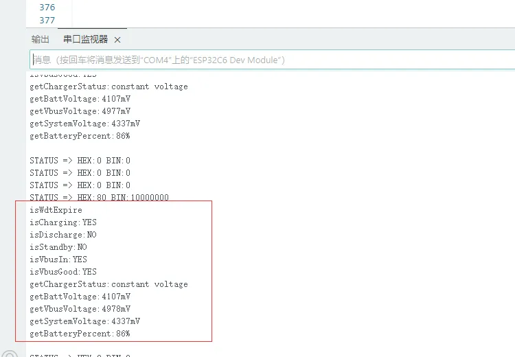
03_axp2101_example
This example demonstrates how to use a power management chip and print battery-related information
Code
03_axp2101_example.ino
#define XPOWERS_CHIP_AXP2101

#include <Wire.h>
#include <Arduino.h>
#include "XPowersLib.h"

#ifndef CONFIG_PMU_SDA
#define CONFIG_PMU_SDA 7
#endif

#ifndef CONFIG_PMU_SCL
#define CONFIG_PMU_SCL 8
#endif

#ifndef CONFIG_PMU_IRQ
#define CONFIG_PMU_IRQ -1
#endif

bool  pmu_flag = 0;
XPowersPMU power;

const uint8_t i2c_sda = CONFIG_PMU_SDA;
const uint8_t i2c_scl = CONFIG_PMU_SCL;
const uint8_t pmu_irq_pin = CONFIG_PMU_IRQ;

void setFlag(void)
{
    pmu_flag = true;
}


void setup()
{
    Serial.begin(115200);
    delay(1000);
    bool result = power.begin(Wire, AXP2101_SLAVE_ADDRESS, i2c_sda, i2c_scl);

    if (result == false) {
        Serial.println("power is not online..."); while (1)delay(50);
    }

    Serial.printf("getID:0x%x\n", power.getChipID());

    // Set the minimum common working voltage of the PMU VBUS input,
    // below this value will turn off the PMU
    power.setVbusVoltageLimit(XPOWERS_AXP2101_VBUS_VOL_LIM_4V36);

    // Set the maximum current of the PMU VBUS input,
    // higher than this value will turn off the PMU
    power.setVbusCurrentLimit(XPOWERS_AXP2101_VBUS_CUR_LIM_1500MA);


    // Get the VSYS shutdown voltage
    uint16_t vol = power.getSysPowerDownVoltage();
    Serial.printf("->  getSysPowerDownVoltage:%u\n", vol);

    // Set VSY off voltage as 2600mV , Adjustment range 2600mV ~ 3300mV
    power.setSysPowerDownVoltage(2600);

    vol = power.getSysPowerDownVoltage();
    Serial.printf("->  getSysPowerDownVoltage:%u\n", vol);


    // DC1 IMAX=2A
    // 1500~3400mV,100mV/step,20steps
    power.setDC1Voltage(3300);
    Serial.printf("DC1  : %s   Voltage:%u mV \n",  power.isEnableDC1()  ? "+" : "-", power.getDC1Voltage());

    // DC2 IMAX=2A
    // 500~1200mV  10mV/step,71steps
    // 1220~1540mV 20mV/step,17steps
    power.setDC2Voltage(1000);
    Serial.printf("DC2  : %s   Voltage:%u mV \n",  power.isEnableDC2()  ? "+" : "-", power.getDC2Voltage());

    // DC3 IMAX=2A
    // 500~1200mV,10mV/step,71steps
    // 1220~1540mV,20mV/step,17steps
    // 1600~3400mV,100mV/step,19steps
    power.setDC3Voltage(3300);
    Serial.printf("DC3  : %s   Voltage:%u mV \n",  power.isEnableDC3()  ? "+" : "-", power.getDC3Voltage());

    // DCDC4 IMAX=1.5A
    // 500~1200mV,10mV/step,71steps
    // 1220~1840mV,20mV/step,32steps
    power.setDC4Voltage(1000);
    Serial.printf("DC4  : %s   Voltage:%u mV \n",  power.isEnableDC4()  ? "+" : "-", power.getDC4Voltage());

    // DC5 IMAX=2A
    // 1200mV
    // 1400~3700mV,100mV/step,24steps
    power.setDC5Voltage(3300);
    Serial.printf("DC5  : %s   Voltage:%u mV \n",  power.isEnableDC5()  ? "+" : "-", power.getDC5Voltage());

    // ALDO1 IMAX=300mA
    //500~3500mV, 100mV/step,31steps
    power.setALDO1Voltage(3300);

    // ALDO2 IMAX=300mA
    //500~3500mV, 100mV/step,31steps
    power.setALDO2Voltage(3300);

    // ALDO3 IMAX=300mA
    //500~3500mV, 100mV/step,31steps
    power.setALDO3Voltage(3300);

    // ALDO4 IMAX=300mA
    //500~3500mV, 100mV/step,31steps
    power.setALDO4Voltage(3300);

    // BLDO1 IMAX=300mA
    //500~3500mV, 100mV/step,31steps
    power.setBLDO1Voltage(3300);

    // BLDO2 IMAX=300mA
    //500~3500mV, 100mV/step,31steps
    power.setBLDO2Voltage(3300);

    //CPUSLDO IMAX=30mA
    // 500~1400mV,50mV/step,19steps
    power.setCPUSLDOVoltage(1000);

    // DLDO1 IMAX=300mA
    //500~3400mV, 100mV/step,29steps
    power.setDLDO1Voltage(3300);

    // DLDO2 IMAX=300mA
    //500~1400mV, 50mV/step,2steps
    power.setDLDO2Voltage(3300);


    // power.enableDC1();
    power.disableDC2();
    power.disableDC3();
    power.disableDC4();
    power.disableDC5();
    power.enableALDO1();
    power.disableALDO2();
    power.disableALDO3();
    power.disableALDO4();
    power.disableBLDO1();
    power.disableBLDO2();
    power.disableCPUSLDO();
    power.disableDLDO1();
    power.disableDLDO2();


    Serial.println("DCDC=======================================================================");
    Serial.printf("DC1  : %s   Voltage:%u mV \n",  power.isEnableDC1()  ? "+" : "-", power.getDC1Voltage());
    Serial.printf("DC2  : %s   Voltage:%u mV \n",  power.isEnableDC2()  ? "+" : "-", power.getDC2Voltage());
    Serial.printf("DC3  : %s   Voltage:%u mV \n",  power.isEnableDC3()  ? "+" : "-", power.getDC3Voltage());
    Serial.printf("DC4  : %s   Voltage:%u mV \n",  power.isEnableDC4()  ? "+" : "-", power.getDC4Voltage());
    Serial.printf("DC5  : %s   Voltage:%u mV \n",  power.isEnableDC5()  ? "+" : "-", power.getDC5Voltage());
    Serial.println("ALDO=======================================================================");
    Serial.printf("ALDO1: %s   Voltage:%u mV\n",  power.isEnableALDO1()  ? "+" : "-", power.getALDO1Voltage());
    Serial.printf("ALDO2: %s   Voltage:%u mV\n",  power.isEnableALDO2()  ? "+" : "-", power.getALDO2Voltage());
    Serial.printf("ALDO3: %s   Voltage:%u mV\n",  power.isEnableALDO3()  ? "+" : "-", power.getALDO3Voltage());
    Serial.printf("ALDO4: %s   Voltage:%u mV\n",  power.isEnableALDO4()  ? "+" : "-", power.getALDO4Voltage());
    Serial.println("BLDO=======================================================================");
    Serial.printf("BLDO1: %s   Voltage:%u mV\n",  power.isEnableBLDO1()  ? "+" : "-", power.getBLDO1Voltage());
    Serial.printf("BLDO2: %s   Voltage:%u mV\n",  power.isEnableBLDO2()  ? "+" : "-", power.getBLDO2Voltage());
    Serial.println("CPUSLDO====================================================================");
    Serial.printf("CPUSLDO: %s Voltage:%u mV\n",  power.isEnableCPUSLDO() ? "+" : "-", power.getCPUSLDOVoltage());
    Serial.println("DLDO=======================================================================");
    Serial.printf("DLDO1: %s   Voltage:%u mV\n",  power.isEnableDLDO1()  ? "+" : "-", power.getDLDO1Voltage());
    Serial.printf("DLDO2: %s   Voltage:%u mV\n",  power.isEnableDLDO2()  ? "+" : "-", power.getDLDO2Voltage());
    Serial.println("===========================================================================");

    // Set the time of pressing the button to turn off
    power.setPowerKeyPressOffTime(XPOWERS_POWEROFF_4S);
    uint8_t opt = power.getPowerKeyPressOffTime();
    Serial.print("PowerKeyPressOffTime:");
    switch (opt) {
    case XPOWERS_POWEROFF_4S: Serial.println("4 Second");
        break;
    case XPOWERS_POWEROFF_6S: Serial.println("6 Second");
        break;
    case XPOWERS_POWEROFF_8S: Serial.println("8 Second");
        break;
    case XPOWERS_POWEROFF_10S: Serial.println("10 Second");
        break;
    default:
        break;
    }
    // Set the button power-on press time
    power.setPowerKeyPressOnTime(XPOWERS_POWERON_128MS);
    opt = power.getPowerKeyPressOnTime();
    Serial.print("PowerKeyPressOnTime:");
    switch (opt) {
    case XPOWERS_POWERON_128MS: Serial.println("128 Ms");
        break;
    case XPOWERS_POWERON_512MS: Serial.println("512 Ms");
        break;
    case XPOWERS_POWERON_1S: Serial.println("1 Second");
        break;
    case XPOWERS_POWERON_2S: Serial.println("2 Second");
        break;
    default:
        break;
    }

    Serial.println("===========================================================================");

    bool en;

    // DCDC 120%(130%) high voltage turn off PMIC function
    en = power.getDCHighVoltagePowerDownEn();
    Serial.print("getDCHighVoltagePowerDownEn:");
    Serial.println(en ? "ENABLE" : "DISABLE");
    // DCDC1 85% low voltage turn off PMIC function
    en = power.getDC1LowVoltagePowerDownEn();
    Serial.print("getDC1LowVoltagePowerDownEn:");
    Serial.println(en ? "ENABLE" : "DISABLE");
    // DCDC2 85% low voltage turn off PMIC function
    en = power.getDC2LowVoltagePowerDownEn();
    Serial.print("getDC2LowVoltagePowerDownEn:");
    Serial.println(en ? "ENABLE" : "DISABLE");
    // DCDC3 85% low voltage turn off PMIC function
    en = power.getDC3LowVoltagePowerDownEn();
    Serial.print("getDC3LowVoltagePowerDownEn:");
    Serial.println(en ? "ENABLE" : "DISABLE");
    // DCDC4 85% low voltage turn off PMIC function
    en = power.getDC4LowVoltagePowerDownEn();
    Serial.print("getDC4LowVoltagePowerDownEn:");
    Serial.println(en ? "ENABLE" : "DISABLE");
    // DCDC5 85% low voltage turn off PMIC function
    en = power.getDC5LowVoltagePowerDownEn();
    Serial.print("getDC5LowVoltagePowerDownEn:");
    Serial.println(en ? "ENABLE" : "DISABLE");

    // power.setDCHighVoltagePowerDown(true);
    // power.setDC1LowVoltagePowerDown(true);
    // power.setDC2LowVoltagePowerDown(true);
    // power.setDC3LowVoltagePowerDown(true);
    // power.setDC4LowVoltagePowerDown(true);
    // power.setDC5LowVoltagePowerDown(true);

    // It is necessary to disable the detection function of the TS pin on the board
    // without the battery temperature detection function, otherwise it will cause abnormal charging
    power.disableTSPinMeasure();

    // power.enableTemperatureMeasure();

    // Enable internal ADC detection
    power.enableBattDetection();
    power.enableVbusVoltageMeasure();
    power.enableBattVoltageMeasure();
    power.enableSystemVoltageMeasure();


    /*
      The default setting is CHGLED is automatically controlled by the PMU.
    - XPOWERS_CHG_LED_OFF,
    - XPOWERS_CHG_LED_BLINK_1HZ,
    - XPOWERS_CHG_LED_BLINK_4HZ,
    - XPOWERS_CHG_LED_ON,
    - XPOWERS_CHG_LED_CTRL_CHG,
    * */
    power.setChargingLedMode(XPOWERS_CHG_LED_OFF);


    // Force add pull-up
    pinMode(pmu_irq_pin, INPUT_PULLUP);
    attachInterrupt(pmu_irq_pin, setFlag, FALLING);


    // Disable all interrupts
    power.disableIRQ(XPOWERS_AXP2101_ALL_IRQ);
    // Clear all interrupt flags
    power.clearIrqStatus();
    // Enable the required interrupt function
    power.enableIRQ(
        XPOWERS_AXP2101_BAT_INSERT_IRQ    | XPOWERS_AXP2101_BAT_REMOVE_IRQ      |   //BATTERY
        XPOWERS_AXP2101_VBUS_INSERT_IRQ   | XPOWERS_AXP2101_VBUS_REMOVE_IRQ     |   //VBUS
        XPOWERS_AXP2101_PKEY_SHORT_IRQ    | XPOWERS_AXP2101_PKEY_LONG_IRQ       |   //POWER KEY
        XPOWERS_AXP2101_BAT_CHG_DONE_IRQ  | XPOWERS_AXP2101_BAT_CHG_START_IRQ       //CHARGE
        // XPOWERS_AXP2101_PKEY_NEGATIVE_IRQ | XPOWERS_AXP2101_PKEY_POSITIVE_IRQ   |   //POWER KEY
    );

    // Set the precharge charging current
    power.setPrechargeCurr(XPOWERS_AXP2101_PRECHARGE_50MA);
    // Set constant current charge current limit
    power.setChargerConstantCurr(XPOWERS_AXP2101_CHG_CUR_200MA);
    // Set stop charging termination current
    power.setChargerTerminationCurr(XPOWERS_AXP2101_CHG_ITERM_25MA);

    // Set charge cut-off voltage
    power.setChargeTargetVoltage(XPOWERS_AXP2101_CHG_VOL_4V1);

    // Set the watchdog trigger event type
    power.setWatchdogConfig(XPOWERS_AXP2101_WDT_IRQ_TO_PIN);
    // Set watchdog timeout
    power.setWatchdogTimeout(XPOWERS_AXP2101_WDT_TIMEOUT_4S);
    // Enable watchdog to trigger interrupt event
    power.enableWatchdog();

    // power.disableWatchdog();

    // Enable Button Battery charge
    power.enableButtonBatteryCharge();

    // Set Button Battery charge voltage
    power.setButtonBatteryChargeVoltage(3300);

}

void printPMU()
{
    Serial.print("isCharging:"); Serial.println(power.isCharging() ? "YES" : "NO");
    Serial.print("isDischarge:"); Serial.println(power.isDischarge() ? "YES" : "NO");
    Serial.print("isStandby:"); Serial.println(power.isStandby() ? "YES" : "NO");
    Serial.print("isVbusIn:"); Serial.println(power.isVbusIn() ? "YES" : "NO");
    Serial.print("isVbusGood:"); Serial.println(power.isVbusGood() ? "YES" : "NO");
    Serial.print("getChargerStatus:");
    uint8_t charge_status = power.getChargerStatus();
    if (charge_status == XPOWERS_AXP2101_CHG_TRI_STATE) {
        Serial.println("tri_charge");
    } else if (charge_status == XPOWERS_AXP2101_CHG_PRE_STATE) {
        Serial.println("pre_charge");
    } else if (charge_status == XPOWERS_AXP2101_CHG_CC_STATE) {
        Serial.println("constant charge");
    } else if (charge_status == XPOWERS_AXP2101_CHG_CV_STATE) {
        Serial.println("constant voltage");
    } else if (charge_status == XPOWERS_AXP2101_CHG_DONE_STATE) {
        Serial.println("charge done");
    } else if (charge_status == XPOWERS_AXP2101_CHG_STOP_STATE) {
        Serial.println("not charge");
    }

    Serial.print("getBattVoltage:"); Serial.print(power.getBattVoltage()); Serial.println("mV");
    Serial.print("getVbusVoltage:"); Serial.print(power.getVbusVoltage()); Serial.println("mV");
    Serial.print("getSystemVoltage:"); Serial.print(power.getSystemVoltage()); Serial.println("mV");

    // The battery percentage may be inaccurate at first use, the PMU will automatically
    // learn the battery curve and will automatically calibrate the battery percentage
    // after a charge and discharge cycle
    if (power.isBatteryConnect()) {
        Serial.print("getBatteryPercent:"); Serial.print(power.getBatteryPercent()); Serial.println("%");
    }

    Serial.println();
}


void enterPmuSleep(void)
{
    // Set the wake-up source to PWRKEY
    power.wakeupControl(XPOWERS_AXP2101_WAKEUP_IRQ_PIN_TO_LOW, true);

    // Set sleep flag
    power.enableSleep();

    power.disableDC2();
    power.disableDC3();
    power.disableDC4();
    power.disableDC5();

    power.disableALDO1();
    power.disableALDO2();
    power.disableALDO3();
    power.disableALDO4();

    power.disableBLDO1();
    power.disableBLDO2();

    power.disableCPUSLDO();
    power.disableDLDO1();
    power.disableDLDO2();

    // Finally, turn off the power of the control chip
    power.disableDC1();
}

void loop()
{

    if (pmu_flag) {

        pmu_flag = false;

        // Get PMU Interrupt Status Register
        uint32_t status = power.getIrqStatus();
        Serial.print("STATUS => HEX:");
        Serial.print(status, HEX);
        Serial.print(" BIN:");
        Serial.println(status, BIN);

        if (power.isDropWarningLevel2Irq()) {
            Serial.println("isDropWarningLevel2");
        }
        if (power.isDropWarningLevel1Irq()) {
            Serial.println("isDropWarningLevel1");
        }
        if (power.isGaugeWdtTimeoutIrq()) {
            Serial.println("isWdtTimeout");
        }
        if (power.isBatChargerOverTemperatureIrq()) {
            Serial.println("isBatChargeOverTemperature");
        }
        if (power.isBatWorkOverTemperatureIrq()) {
            Serial.println("isBatWorkOverTemperature");
        }
        if (power.isBatWorkUnderTemperatureIrq()) {
            Serial.println("isBatWorkUnderTemperature");
        }
        if (power.isVbusInsertIrq()) {
            Serial.println("isVbusInsert");
        }
        if (power.isVbusRemoveIrq()) {
            Serial.println("isVbusRemove");
        }
        if (power.isBatInsertIrq()) {
            Serial.println("isBatInsert");
        }
        if (power.isBatRemoveIrq()) {
            Serial.println("isBatRemove");
        }

        if (power.isPekeyShortPressIrq()) {
            Serial.println("isPekeyShortPress");
            // enterPmuSleep();

            Serial.print("Read pmu data buffer .");
            uint8_t data[4] = {0};
            power.readDataBuffer(data, XPOWERS_AXP2101_DATA_BUFFER_SIZE);
            for (int i = 0; i < 4; ++i) {
                Serial.print(data[i]);
                Serial.print(",");
            }
            Serial.println();
        }

        if (power.isPekeyLongPressIrq()) {
            Serial.println("isPekeyLongPress");
            Serial.println("write pmu data buffer .");
            uint8_t data[4] = {1, 2, 3, 4};
            power.writeDataBuffer(data, XPOWERS_AXP2101_DATA_BUFFER_SIZE);
        }

        if (power.isPekeyNegativeIrq()) {
            Serial.println("isPekeyNegative");
        }
        if (power.isPekeyPositiveIrq()) {
            Serial.println("isPekeyPositive");
        }
        if (power.isWdtExpireIrq()) {
            Serial.println("isWdtExpire");
            printPMU();
        }
        if (power.isLdoOverCurrentIrq()) {
            Serial.println("isLdoOverCurrentIrq");
        }
        if (power.isBatfetOverCurrentIrq()) {
            Serial.println("isBatfetOverCurrentIrq");
        }
        if (power.isBatChargeDoneIrq()) {
            Serial.println("isBatChargeDone");
        }
        if (power.isBatChargeStartIrq()) {
            Serial.println("isBatChargeStart");
        }
        if (power.isBatDieOverTemperatureIrq()) {
            Serial.println("isBatDieOverTemperature");
        }
        if (power.isChargeOverTimeoutIrq()) {
            Serial.println("isChargeOverTimeout");
        }
        if (power.isBatOverVoltageIrq()) {
            Serial.println("isBatOverVoltage");
        }

        // Clear PMU Interrupt Status Register
        power.clearIrqStatus();

    }
    delay(10);
}
Code Analysis
-
Initialize QMI8658:
bool result = power.begin(Wire, AXP2101_SLAVE_ADDRESS, i2c_sda, i2c_scl);
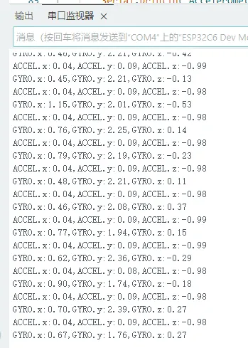
04_qmi8658_example
This example prints the running results of imu qmi8658
Code
04_qmi8658_example.ino
#include <Arduino.h>
#include <Wire.h>
#include <SPI.h>
#include "SensorQMI8658.hpp"


// #define USE_I2C              //Using the I2C interface

#ifndef SENSOR_SDA
#define SENSOR_SDA  7
#endif

#ifndef SENSOR_SCL
#define SENSOR_SCL  8
#endif


#ifndef IMU_IRQ
#define IMU_IRQ  10
#endif


SensorQMI8658 qmi;

IMUdata acc;
IMUdata gyr;


void setup()
{
    Serial.begin(115200);
    while (!Serial);

    bool ret = false;

    ret = qmi.begin(Wire, QMI8658_L_SLAVE_ADDRESS, SENSOR_SDA, SENSOR_SCL);

    if (!ret) {
        Serial.println("Failed to find QMI8658 - check your wiring!");
        while (1) {
            delay(1000);
        }
    }

    /* Get chip id*/
    Serial.print("Device ID:");
    Serial.println(qmi.getChipID(), HEX);


    if (qmi.selfTestAccel()) {
        Serial.println("Accelerometer self-test successful");
    }else{
        Serial.println("Accelerometer self-test failed!");
    }

    if (qmi.selfTestGyro()) {
        Serial.println("Gyroscope self-test successful");
    }else{
        Serial.println("Gyroscope self-test failed!");
    }


    qmi.configAccelerometer(
        /*
         * ACC_RANGE_2G
         * ACC_RANGE_4G
         * ACC_RANGE_8G
         * ACC_RANGE_16G
         * */
        SensorQMI8658::ACC_RANGE_4G,
        /*
         * ACC_ODR_1000H
         * ACC_ODR_500Hz
         * ACC_ODR_250Hz
         * ACC_ODR_125Hz
         * ACC_ODR_62_5Hz
         * ACC_ODR_31_25Hz
         * ACC_ODR_LOWPOWER_128Hz
         * ACC_ODR_LOWPOWER_21Hz
         * ACC_ODR_LOWPOWER_11Hz
         * ACC_ODR_LOWPOWER_3H
        * */
        SensorQMI8658::ACC_ODR_1000Hz,
        /*
        *  LPF_MODE_0     //2.66% of ODR
        *  LPF_MODE_1     //3.63% of ODR
        *  LPF_MODE_2     //5.39% of ODR
        *  LPF_MODE_3     //13.37% of ODR
        *  LPF_OFF        // OFF Low-Pass Fitter
        * */
        SensorQMI8658::LPF_MODE_0);


    qmi.configGyroscope(
        /*
        * GYR_RANGE_16DPS
        * GYR_RANGE_32DPS
        * GYR_RANGE_64DPS
        * GYR_RANGE_128DPS
        * GYR_RANGE_256DPS
        * GYR_RANGE_512DPS
        * GYR_RANGE_1024DPS
        * */
        SensorQMI8658::GYR_RANGE_64DPS,
        /*
         * GYR_ODR_7174_4Hz
         * GYR_ODR_3587_2Hz
         * GYR_ODR_1793_6Hz
         * GYR_ODR_896_8Hz
         * GYR_ODR_448_4Hz
         * GYR_ODR_224_2Hz
         * GYR_ODR_112_1Hz
         * GYR_ODR_56_05Hz
         * GYR_ODR_28_025H
         * */
        SensorQMI8658::GYR_ODR_896_8Hz,
        /*
        *  LPF_MODE_0     //2.66% of ODR
        *  LPF_MODE_1     //3.63% of ODR
        *  LPF_MODE_2     //5.39% of ODR
        *  LPF_MODE_3     //13.37% of ODR
        *  LPF_OFF        // OFF Low-Pass Fitter
        * */
        SensorQMI8658::LPF_MODE_3);


    /*
    * If both the accelerometer and gyroscope sensors are turned on at the same time,
    * the output frequency will be based on the gyroscope output frequency.
    * The example configuration is 896.8HZ output frequency,
    * so the acceleration output frequency is also limited to 896.8HZ
    * */
    qmi.enableGyroscope();
    qmi.enableAccelerometer();

    // Print register configuration information
    qmi.dumpCtrlRegister();


#if IMU_IRQ > 0
// If you want to enable interrupts, then turn on the interrupt enable
    qmi.enableINT(SensorQMI8658::INTERRUPT_PIN_1, true);
    qmi.enableINT(SensorQMI8658::INTERRUPT_PIN_2, false);
#endif

    Serial.println("Read data now...");

}


void loop()
{
    // When the interrupt pin is passed in through setPin,
    // the GPIO will be read to see if the data is ready.
    if (qmi.getDataReady()) {

        // Serial.print("Timestamp:");
        // Serial.print(qmi.getTimestamp());

        if (qmi.getAccelerometer(acc.x, acc.y, acc.z)) {

            // Print to serial plotter
            Serial.print("ACCEL.x:"); Serial.print(acc.x); Serial.print(",");
            Serial.print("ACCEL.y:"); Serial.print(acc.y); Serial.print(",");
            Serial.print("ACCEL.z:"); Serial.print(acc.z); Serial.println();

            /*
            m2/s to mg
            Serial.print(" ACCEL.x:"); Serial.print(acc.x * 1000); Serial.println(" mg");
            Serial.print(",ACCEL.y:"); Serial.print(acc.y * 1000); Serial.println(" mg");
            Serial.print(",ACCEL.z:"); Serial.print(acc.z * 1000); Serial.println(" mg");
            */

        }

        if (qmi.getGyroscope(gyr.x, gyr.y, gyr.z)) {


            // Print to serial plotter
            Serial.print(" GYRO.x:"); Serial.print(gyr.x); Serial.print(",");
            Serial.print(" GYRO.y:"); Serial.print(gyr.y); Serial.print(",");
            Serial.print(" GYRO.z:"); Serial.print(gyr.z); Serial.println();


            // Serial.print(" GYRO.x:"); Serial.print(gyr.x); Serial.println(" degrees/sec");
            // Serial.print(",GYRO.y:"); Serial.print(gyr.y); Serial.println(" degrees/sec");
            // Serial.print(",GYRO.z:"); Serial.print(gyr.z); Serial.println(" degrees/sec");

        }

        // Serial.print("Temperature:");
        // Serial.print(qmi.getTemperature_C());
        // Serial.println(" degrees C");

    }
    delay(100);
}
Code Analysis
-
Initialize qmi8658:
ret = qmi.begin(Wire, QMI8658_L_SLAVE_ADDRESS, SENSOR_SDA, SENSOR_SCL);
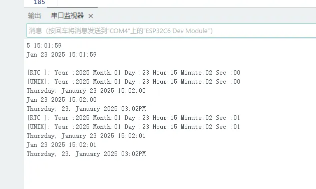
05_pcf85063_example
This example prints the value of RTC real-time clock pcf85063
Code
05_pcf85063_example.ino
#include <Wire.h>
#include <SPI.h>
#include <Arduino.h>
#include <SensorPCF85063.hpp>

#ifndef SENSOR_SDA
#define SENSOR_SDA  7
#endif

#ifndef SENSOR_SCL
#define SENSOR_SCL  8
#endif

#ifndef SENSOR_IRQ
#define SENSOR_IRQ  15
#endif

SensorPCF85063 rtc;
uint32_t interval = 0;
uint32_t loopCount = 0;

void printInt(int val)
{
    if (val < 10) {
        Serial.print("0");
    }
    Serial.print(val);
}


void setup()
{

    Serial.begin(115200);
    // Wait for the serial port to be ready
    while (!Serial);

    // Try to initialize the RTC module using I2C with specified SDA and SCL pins
    if (!rtc.begin(Wire, SENSOR_SDA, SENSOR_SCL)) {
        Serial.println("Failed to find PCF85063 - check your wiring!");
        // Enter an infinite loop to halt the program
        while (1) {
            delay(1000);
        }
    }

    uint16_t year = 2023;
    uint8_t month = 9;
    uint8_t day = 7;
    uint8_t hour = 11;
    uint8_t minute = 24;
    uint8_t second = 30;

    // Set the defined date and time on the RTC
    rtc.setDateTime(year, month, day, hour, minute, second);

    if (!rtc.isClockIntegrityGuaranteed()) {
        Serial.println("[ERROR]:Clock integrity is not guaranteed; oscillator has stopped or has been interrupted");
    }
}

void loop()
{
    // Check if one second has passed since the last update
    if (millis() > interval) {

        // Update the interval to the current time
        interval = millis() + 1000;

        // Retrieve the current date and time from the RTC
        RTC_DateTime datetime = rtc.getDateTime();

        Serial.print("[RTC ]:");
        Serial.print(" Year :");  printInt(datetime.getYear());
        Serial.print(" Month:");  printInt(datetime.getMonth());
        Serial.print(" Day :");   printInt(datetime.getDay());
        Serial.print(" Hour:");   printInt(datetime.getHour());
        Serial.print(" Minute:"); printInt(datetime.getMinute());
        Serial.print(" Sec :");   printInt(datetime.getSecond());
        Serial.println();

        // Convert the RTC date and time to Unix time
        struct tm info = datetime.toUnixTime();
        Serial.print("[UNIX]:");
        Serial.print(" Year :");  printInt(info.tm_year + 1900); // tm_year starts counting from 1900
        Serial.print(" Month:");  printInt(info.tm_mon + 1);     // tm_mon range is 0 - 11, 0 means January
        Serial.print(" Day :");   printInt(info.tm_mday);
        Serial.print(" Hour:");   printInt(info.tm_hour);
        Serial.print(" Minute:"); printInt(info.tm_min);
        Serial.print(" Sec :");   printInt(info.tm_sec);
        Serial.println();

        // Set a new Unix time at the 10th loop iteration
        if (loopCount == 10) {
            Serial.print("Set Unix Time:");
            Serial.println();
            Serial.println();
            struct tm utc_tm;
            utc_tm.tm_year = 2025 - 1900; // tm_year starts counting from 1900
            utc_tm.tm_mon = 0;            // tm_mon range is 0 - 11, 0 means January
            utc_tm.tm_mday = 23;
            utc_tm.tm_hour = 7;
            utc_tm.tm_min = 1;
            utc_tm.tm_sec = 28;
            rtc.setDateTime(utc_tm);
        }

        // Set a UTC time with a time zone offset of 8 hours at the 20th loop iteration
        if (loopCount == 20) {
            Serial.print("Set UTC time to time zone offset 8 hours:");
            Serial.println();
            Serial.println();
            struct tm utc_tm;
            utc_tm.tm_year = 2025 - 1900; // tm_year starts counting from 1900
            utc_tm.tm_mon = 0;            // tm_mon range is 0 - 11, 0 means January
            utc_tm.tm_mday = 23;
            utc_tm.tm_hour = 7;
            utc_tm.tm_min = 1;
            utc_tm.tm_sec = 28;
            rtc.convertUtcToTimezone(utc_tm, 8 * 3600);
            rtc.setDateTime(utc_tm);
        }

        if (loopCount > 30) {

            char buf[64];

            struct tm timeinfo;
            // Get the time C library structure
            rtc.getDateTime(&timeinfo);

            // Format the output using the strftime function
            // For more formats, please refer to :
            // https://man7.org/linux/man-pages/man3/strftime.3.html

            size_t written = strftime(buf, 64, "%A, %B %d %Y %H:%M:%S", &timeinfo);

            if (written != 0) {
                Serial.println(buf);
            }

            written = strftime(buf, 64, "%b %d %Y %H:%M:%S", &timeinfo);
            if (written != 0) {
                Serial.println(buf);
            }

            written = strftime(buf, 64, "%A, %d. %B %Y %I:%M%p", &timeinfo);
            if (written != 0) {
                Serial.println(buf);
            }
        }

        ++loopCount;
    }
}
Code Analysis
-
Initialize qmi8658:
if (!rtc.begin(Wire, SENSOR_SDA, SENSOR_SCL)) {Serial.println("Failed to find PCF85063 - check your wiring!");// Enter an infinite loop to halt the programwhile (1) {delay(1000);}} -
Set the time:
uint16_t year = 2023;uint8_t month = 9;uint8_t day = 7;uint8_t hour = 11;uint8_t minute = 24;uint8_t second = 30;// Set the defined date and time on the RTCrtc.setDateTime(year, month, day, hour, minute, second);
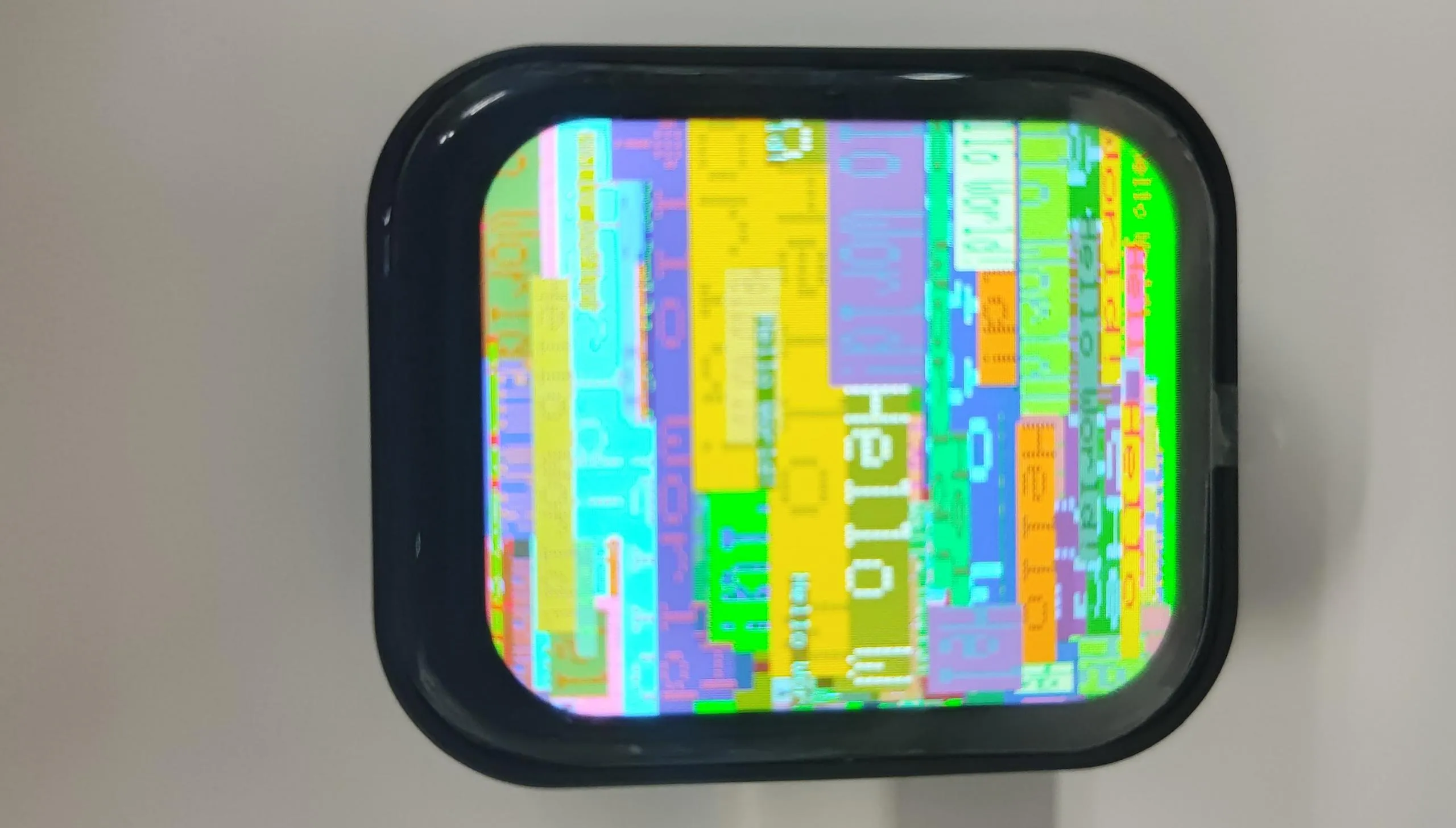
06_gfx_helloworld
This example drives the screen and continuously prints "Hello World!" on the screen.
Code
06_gfx_helloworld.ino
#include <Arduino_GFX_Library.h>

#define LCD_SCK 1
#define LCD_DIN 2
#define LCD_CS 5
#define LCD_DC 3
#define LCD_RST 4
#define LCD_BL 6

#define GFX_BL LCD_BL

Arduino_DataBus *bus = new Arduino_HWSPI(LCD_DC, LCD_CS, LCD_SCK, LCD_DIN);
Arduino_GFX *gfx = new Arduino_ST7789(
  bus, LCD_RST, 0 /* rotation */, true /* IPS */,
  240 /* width */, 284 /* height */);

void setup(void)
{
#ifdef DEV_DEVICE_INIT
  DEV_DEVICE_INIT();
#endif

  Serial.begin(115200);
  // Serial.setDebugOutput(true);
  // while(!Serial);
  Serial.println("Arduino_GFX Hello World example");

  // Init Display
  if (!gfx->begin())
  {
    Serial.println("gfx->begin() failed!");
  }
  gfx->fillScreen(RGB565_BLACK);

#ifdef GFX_BL
  pinMode(GFX_BL, OUTPUT);
  digitalWrite(GFX_BL, HIGH);
#endif

  while (1) {
    gfx->fillScreen(RGB565_BLUE);
    delay(1000);
    gfx->fillScreen(RGB565_RED);
    delay(1000);
    gfx->fillScreen(RGB565_GREEN);
    delay(1000);
  }

  gfx->setCursor(10, 10);
  gfx->setTextColor(RGB565_RED);
  gfx->println("Hello World!");

  delay(5000); // 5 seconds
}

void loop()
{
  gfx->setCursor(random(gfx->width()), random(gfx->height()));
  gfx->setTextColor(random(0xffff), random(0xffff));
  gfx->setTextSize(random(6) /* x scale */, random(6) /* y scale */, random(2) /* pixel_margin */);
  gfx->println("Hello World!");

  delay(1000); // 1 second
}
Code Analysis
-
Initialize the SPI bus and the screen:
Arduino_DataBus *bus = new Arduino_HWSPI(LCD_DC, LCD_CS, LCD_SCK, LCD_DIN);Arduino_GFX *gfx = new Arduino_ST7789(bus, LCD_RST, 0 /* rotation */, true /* IPS */,240 /* width */, 284 /* height */); -
Fill with "Hello World":
gfx->setCursor(random(gfx->width()), random(gfx->height()));gfx->setTextColor(random(0xffff), random(0xffff));gfx->setTextSize(random(6) /* x scale */, random(6) /* y scale */, random(2) /* pixel_margin */);gfx->println("Hello World!");
07_LVGL_Arduino
This example uses the Arduino_GFX_Library to drive the ST7789 screen, while porting LVGL and the touch driver

Code
07_LVGL_Arduino.ino
#include <lvgl.h>
#include <Arduino_GFX_Library.h>
#include "Arduino_DriveBus_Library.h"
#include "lv_conf.h"
#include <demos/lv_demos.h>
#include "HWCDC.h"


HWCDC USBSerial;

#define LCD_SCK 1
#define LCD_DIN 2
#define LCD_CS 5
#define LCD_DC 3
#define LCD_RST 4
#define LCD_BL 6

#define GFX_BL LCD_BL

#define LCD_WIDTH 240
#define LCD_HEIGHT 284

#define IIC_SDA 7
#define IIC_SCL 8

#define TP_INT 11

Arduino_DataBus *bus = new Arduino_HWSPI(LCD_DC, LCD_CS, LCD_SCK, LCD_DIN);
Arduino_GFX *gfx = new Arduino_ST7789(
  bus, LCD_RST, 0 /* rotation */, true /* IPS */,
  LCD_WIDTH /* width */, LCD_HEIGHT /* height */);

std::shared_ptr<Arduino_IIC_DriveBus> IIC_Bus =
  std::make_shared<Arduino_HWIIC>(IIC_SDA, IIC_SCL, &Wire);

void Arduino_IIC_Touch_Interrupt(void);

std::unique_ptr<Arduino_IIC> CST816T(new Arduino_CST816x(IIC_Bus, CST816T_DEVICE_ADDRESS,
                                                         -1, TP_INT, Arduino_IIC_Touch_Interrupt));

void Arduino_IIC_Touch_Interrupt(void) {
  CST816T->IIC_Interrupt_Flag = true;
}

#define EXAMPLE_LVGL_TICK_PERIOD_MS 2

uint32_t screenWidth;
uint32_t screenHeight;

static lv_disp_draw_buf_t draw_buf;
// static lv_color_t buf[screenWidth * screenHeight / 10];


#if LV_USE_LOG != 0
/* Serial debugging */
void my_print(const char *buf) {
  Serial.printf(buf);
  Serial.flush();
}
#endif

/* Display flushing */
void my_disp_flush(lv_disp_drv_t *disp, const lv_area_t *area, lv_color_t *color_p) {
  uint32_t w = (area->x2 - area->x1 + 1);
  uint32_t h = (area->y2 - area->y1 + 1);

#if (LV_COLOR_16_SWAP != 0)
  gfx->draw16bitBeRGBBitmap(area->x1, area->y1, (uint16_t *)&color_p->full, w, h);
#else
  gfx->draw16bitRGBBitmap(area->x1, area->y1, (uint16_t *)&color_p->full, w, h);
#endif

  lv_disp_flush_ready(disp);
}

void example_increase_lvgl_tick(void *arg) {
  /* Tell LVGL how many milliseconds has elapsed */
  lv_tick_inc(EXAMPLE_LVGL_TICK_PERIOD_MS);
}

static uint8_t count = 0;
void example_increase_reboot(void *arg) {
  count++;
  if (count == 30) {
    esp_restart();
  }
}

/*Read the touchpad*/
void my_touchpad_read(lv_indev_drv_t *indev_driver, lv_indev_data_t *data) {
  int32_t touchX = CST816T->IIC_Read_Device_Value(CST816T->Arduino_IIC_Touch::Value_Information::TOUCH_COORDINATE_X);
  int32_t touchY = CST816T->IIC_Read_Device_Value(CST816T->Arduino_IIC_Touch::Value_Information::TOUCH_COORDINATE_Y);

  if (CST816T->IIC_Interrupt_Flag == true) {
    CST816T->IIC_Interrupt_Flag = false;
    data->state = LV_INDEV_STATE_PR;

    /* Set the coordinates with some debounce */
    if (touchX >= 0 && touchY >= 0) {
      data->point.x = touchX;
      data->point.y = touchY;

      USBSerial.printf("Data x: %d, Data y: %d\n", touchX, touchY);
    }
  }else{
    data->state = LV_INDEV_STATE_REL;
  }
}


void setup() {
  USBSerial.begin(115200); /* prepare for possible serial debug */

  while (CST816T->begin() == false) {
    USBSerial.println("CST816T initialization fail");
    delay(2000);
  }
  USBSerial.println("CST816T initialization successfully");

  CST816T->IIC_Write_Device_State(CST816T->Arduino_IIC_Touch::Device::TOUCH_DEVICE_INTERRUPT_MODE,
                                  CST816T->Arduino_IIC_Touch::Device_Mode::TOUCH_DEVICE_INTERRUPT_PERIODIC);

  gfx->begin();
  pinMode(LCD_BL, OUTPUT);
  digitalWrite(LCD_BL, HIGH);

  screenWidth = gfx->width();
  screenHeight = gfx->height();

  lv_init();

  lv_color_t *buf1 = (lv_color_t *)heap_caps_malloc(screenWidth * screenHeight / 4 * sizeof(lv_color_t), MALLOC_CAP_DMA);

  lv_color_t *buf2 = (lv_color_t *)heap_caps_malloc(screenWidth * screenHeight / 4 * sizeof(lv_color_t), MALLOC_CAP_DMA);

  String LVGL_Arduino = "Hello Arduino! ";
  LVGL_Arduino += String('V') + lv_version_major() + "." + lv_version_minor() + "." + lv_version_patch();

  USBSerial.println(LVGL_Arduino);
  USBSerial.println("I am LVGL_Arduino");


#if LV_USE_LOG != 0
  lv_log_register_print_cb(my_print); /* register print function for debugging */
#endif

  lv_disp_draw_buf_init(&draw_buf, buf1, buf2, screenWidth * screenHeight / 4);

  /*Initialize the display*/
  static lv_disp_drv_t disp_drv;
  lv_disp_drv_init(&disp_drv);
  /*Change the following line to your display resolution*/
  disp_drv.hor_res = screenWidth;
  disp_drv.ver_res = screenHeight;
  disp_drv.flush_cb = my_disp_flush;
  disp_drv.draw_buf = &draw_buf;
  lv_disp_drv_register(&disp_drv);

  /*Initialize the (dummy) input device driver*/
  static lv_indev_drv_t indev_drv;
  lv_indev_drv_init(&indev_drv);
  indev_drv.type = LV_INDEV_TYPE_POINTER;
  indev_drv.read_cb = my_touchpad_read;
  lv_indev_drv_register(&indev_drv);

  lv_obj_t *label = lv_label_create(lv_scr_act());
  lv_label_set_text(label, "Hello Ardino and LVGL!");
  lv_obj_align(label, LV_ALIGN_CENTER, 0, 0);

  const esp_timer_create_args_t lvgl_tick_timer_args = {
    .callback = &example_increase_lvgl_tick,
    .name = "lvgl_tick"
  };

  const esp_timer_create_args_t reboot_timer_args = {
    .callback = &example_increase_reboot,
    .name = "reboot"
  };

  esp_timer_handle_t lvgl_tick_timer = NULL;
  esp_timer_create(&lvgl_tick_timer_args, &lvgl_tick_timer);
  esp_timer_start_periodic(lvgl_tick_timer, EXAMPLE_LVGL_TICK_PERIOD_MS * 1000);

  lv_demo_widgets();
  // lv_demo_benchmark();
  // lv_demo_keypad_encoder();
  // lv_demo_music();
  // lv_demo_stress();

  // lv_obj_t *img_obj = lv_img_create(lv_scr_act());
  // lv_img_set_src(img_obj, &img_test3);  // Set the image source to img_test3
  // lv_obj_align(img_obj, LV_ALIGN_CENTER, 0, 0);
  // USBSerial.println("Setup done");
}

void loop() {
  lv_timer_handler(); /* let the GUI do its work */
  delay(5);
}
Code Analysis
-
Initialize the SPI bus and the screen:
Arduino_DataBus *bus = new Arduino_HWSPI(LCD_DC, LCD_CS, LCD_SCK, LCD_DIN);Arduino_GFX *gfx = new Arduino_ST7789(bus, LCD_RST, 0 /* rotation */, true /* IPS */,LCD_WIDTH /* width */, LCD_HEIGHT /* height */); -
Initialize the CST816 touch controller:
std::unique_ptr<Arduino_IIC> CST816T(new Arduino_CST816x(IIC_Bus, CST816T_DEVICE_ADDRESS,-1, TP_INT, Arduino_IIC_Touch_Interrupt)); -
Initialize LVGL, configure the touch driver, and load the LVGL example program:
screenWidth = gfx->width();screenHeight = gfx->height();lv_init();lv_color_t *buf1 = (lv_color_t *)heap_caps_malloc(screenWidth * screenHeight / 4 * sizeof(lv_color_t), MALLOC_CAP_DMA);lv_color_t *buf2 = (lv_color_t *)heap_caps_malloc(screenWidth * screenHeight / 4 * sizeof(lv_color_t), MALLOC_CAP_DMA);String LVGL_Arduino = "Hello Arduino! ";LVGL_Arduino += String('V') + lv_version_major() + "." + lv_version_minor() + "." + lv_version_patch();USBSerial.println(LVGL_Arduino);USBSerial.println("I am LVGL_Arduino");#if LV_USE_LOG != 0lv_log_register_print_cb(my_print); /* register print function for debugging */#endiflv_disp_draw_buf_init(&draw_buf, buf1, buf2, screenWidth * screenHeight / 4);/*Initialize the display*/static lv_disp_drv_t disp_drv;lv_disp_drv_init(&disp_drv);/*Change the following line to your display resolution*/disp_drv.hor_res = screenWidth;disp_drv.ver_res = screenHeight;disp_drv.flush_cb = my_disp_flush;disp_drv.draw_buf = &draw_buf;lv_disp_drv_register(&disp_drv);/*Initialize the (dummy) input device driver*/static lv_indev_drv_t indev_drv;lv_indev_drv_init(&indev_drv);indev_drv.type = LV_INDEV_TYPE_POINTER;indev_drv.read_cb = my_touchpad_read;lv_indev_drv_register(&indev_drv);lv_obj_t *label = lv_label_create(lv_scr_act());lv_label_set_text(label, "Hello Ardino and LVGL!");lv_obj_align(label, LV_ALIGN_CENTER, 0, 0);const esp_timer_create_args_t lvgl_tick_timer_args = {.callback = &example_increase_lvgl_tick,.name = "lvgl_tick"};const esp_timer_create_args_t reboot_timer_args = {.callback = &example_increase_reboot,.name = "reboot"};esp_timer_handle_t lvgl_tick_timer = NULL;esp_timer_create(&lvgl_tick_timer_args, &lvgl_tick_timer);esp_timer_start_periodic(lvgl_tick_timer, EXAMPLE_LVGL_TICK_PERIOD_MS * 1000);lv_demo_widgets();