Working with Arduino
This section describes the environment setup, upload steps, and running behavior for the Arduino examples. Prepare the development board, a USB data cable that supports data transfer, and download the ESP32-C6-Touch-LCD-2.8 Example Programs.
This chapter includes the following sections. Please read as needed:
Arduino Getting Started
New to Arduino ESP32 development and looking for a quick start? We have prepared a comprehensive Getting Started Tutorial for you.
- Section 0: Getting to Know ESP32
- Section 1: Installing and Configuring Arduino IDE
- Section 2: Arduino Basics
- Section 3: Digital Output/Input
- Section 4: Analog Input
- Section 5: Pulse Width Modulation (PWM)
- Section 6: Serial Communication (UART)
- Section 7: I2C Communication
- Section 8: SPI Communication
- Section 9: Wi-Fi Basics
- Section 10: Web Server
- Section 11: Bluetooth
- Section 12: LVGL GUI Development
- Section 13: Comprehensive Project
Note: This tutorial uses the ESP32-S3-Zero as a reference example, and all hardware code is based on its pinout. Before you start, we recommend checking the pinout of your development board to ensure the pin configuration is correct.
Set Up the Development Environment
1. Install Arduino IDE and the Board Support Package
Refer to the tutorial Install and Configure Arduino IDE to install the IDE. In "File" > "Preferences", add the following to "Additional Boards Manager URLs":
https://espressif.github.io/arduino-esp32/package_esp32_index.json
Open the Boards Manager and install esp32 by Espressif Systems 3.3.12.
This document corresponds to Arduino-ESP32 3.3.12, and the examples are located in examples/arduino/examples. The display examples use the bundled LVGL 8.4.0; do not replace it with LVGL 9.
2. Configure the Example Libraries
The libraries and configuration files required by the examples are provided with the source code in examples/arduino/libraries:
| Library or File Name | Description | Version | Installation Method |
|---|---|---|---|
board_config | CH32V003 IO expander, battery ADC, ST7789 display, and CST3530 touch drivers | 1.0.0 | Use the bundled files |
SensorLib | Sensor drivers such as PCF85063 | 0.3.1 | Use the bundled files |
lvgl | Graphics interface framework | 8.4.0 | Use the bundled files |
lv_conf.h | LVGL configuration file | Provided with the project | Place alongside the lvgl folder |
Set "Sketchbook location" in "File" > "Preferences" to the examples/arduino folder in the downloaded repository, then restart Arduino IDE. The IDE will load the bundled libraries from the libraries directory under that location:
examples/arduino/
├── examples/
│   ├── 01_exio/
│   ├── 02_I2C_qmi8658/
│   ├── 03_SD_Card/
│   ├── 04_I2C_pcf85063/
│   ├── 05_shtc3/
│   ├── 06_lvgl_demo/
│   └── 07_battery_voltage/
└── libraries/
    ├── board_config/
    ├── lvgl/
    ├── SensorLib/
    └── lv_conf.h
- Keep
libraries/lv_conf.hand place it alongside thelvglfolder. - If you use your own project folder, you can copy the entire contents of the bundled
librariesinto thelibrariesdirectory of that project folder.
This tutorial uses the libraries and configuration files provided with the source code. Do not install multiple versions of LVGL at the same time, to avoid selecting the wrong library during compilation. The interfaces of LVGL 8 and LVGL 9 are different; replacing the library version or mixing in display and touch drivers from other products may cause compilation failures or abnormal operation.
3. Select Project Parameters
Connect the development board via USB and configure the following in the "Tools" menu:
| Option | Setting |
|---|---|
| Board | ESP32C6 Dev Module |
| Flash Size | 16 MB |
| Flash Mode | QIO |
| PSRAM | Not supported; no need to enable |
| Partition Scheme | 16M Flash (3MB APP/9.9MB FATFS) |
| Port | The serial port actually corresponding to the development board |
| Serial Monitor Baud Rate | 115200 |
The board has 16 MB Flash and no PSRAM; keep the example's drawing buffers and memory configuration.
4. Compile and Upload
- From
examples/arduino/examples, open the.inofile with the same name inside the desired example directory. - Click "Verify" to compile. After compilation succeeds, click "Upload".
- After uploading, open the serial monitor, set the baud rate to 115200, and press RESET to view the boot information.
- Operate the development board as described below and check the screen or serial port behavior.
If you cannot connect during upload, disconnect USB, hold BOOT, reconnect USB, release BOOT once the port is detected, and then upload again.
When using Arduino CLI, you can run the following commands in the repository root directory. Replace COM5 with the actual serial port:
arduino-cli core install esp32:esp32@3.3.12
arduino-cli compile --fqbn esp32:esp32:esp32c6:FlashSize=16M,FlashMode=qio,PartitionScheme=app3M_fat9M_16MB --libraries examples/arduino/libraries examples/arduino/examples/06_lvgl_demo
arduino-cli upload -p COM5 --fqbn esp32:esp32:esp32c6:FlashSize=16M,FlashMode=qio,PartitionScheme=app3M_fat9M_16MB examples/arduino/examples/06_lvgl_demo
After flashing a basic example, the development board runs that example. To run the APP desktop, compile and flash the standalone factory project examples/factory.
Example Programs
The examples are located in the examples/arduino/examples directory of the source package. The .ino file with the same name in each example folder is the entry file; keep the accompanying source files and header files in the same directory.
| Example | Basic Description | Dependency Library | View Results |
|---|---|---|---|
| 01_exio | EXIO6/7 level output and backlight switching | board_config | Serial port, level, and backlight changes |
| 02_I2C_qmi8658 | Three-axis acceleration and angular velocity | Drivers provided with the example | Serial port |
| 03_SD_Card | TF card identification and capacity | Built-in Arduino-ESP32 components | Serial port |
| 04_I2C_pcf85063 | RTC setting and reading | SensorLib | Serial port |
| 05_shtc3 | Temperature and humidity reading with CRC check | Arduino-ESP32 built-in Wire | Serial port |
| 06_lvgl_demo | Display, touch coordinates, and backlight adjustment | board_config, lvgl | LCD |
| 07_battery_voltage | Battery voltage and raw ADC value | board_config, lvgl | LCD, serial port |
01_exio
Example Description
Controls EXIO6/7 outputs and the screen backlight through the onboard CH32V003, demonstrating the expanded IO and backlight control interfaces.
Hardware Connection
Connect the development board to the computer using a USB data cable; you can use a multimeter to measure the voltage of the EXIO6/7 header pins relative to GND.
Code Analysis
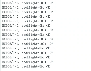
setup(): Initializes the serial port at 115200 baud and callsBoard_IO_Init()to initialize the CH32V003.loop(): Sets the EXIO6/7 levels viaBoard_IO_SetOutput()and toggles the backlight brightness viaBoard_SetBacklight(), executing once per second and outputting the results.
Running Effect
After uploading, the EXIO6/7 outputs toggle between high and low levels every second, the backlight switches between off and full brightness, and the serial port outputs the corresponding status. This example does not display an LCD interface.
The CH32V003 comes preloaded with control firmware, so no separate flashing is required. This example only uses EXIO6/7 as test outputs; the other expanded IOs are used for onboard devices such as the screen, touch, and amplifier, so do not toggle them arbitrarily.
02_I2C_qmi8658
Example Description
Reads the three-axis acceleration and angular velocity of the onboard QMI8658 six-axis sensor via I2C and outputs them through the serial port.
Hardware Connection
Connect the development board to the computer with a USB data cable; no external sensor is required.
Code Analysis
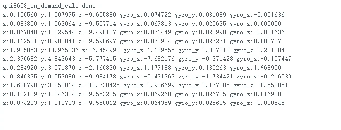
setup(): Initializes the serial port and callsI2C_master_Init()to configure the I2C bus.qmi8658c_example: A task created byxTaskCreate()handles sensor initialization, reading, and serial output;loop()performs no additional operations.
Running Effect
After uploading, open the serial monitor to observe the three-axis acceleration (m/s²) and angular velocity (rad/s), printed about once per second. Gently tilt or rotate the development board and the data will change accordingly. Gravity is still measured when stationary, so the axes are not necessarily zero; this example does not light up the screen.
03_SD_Card
Example Description
Mounts the TF card and outputs the card information and capacity through the serial port.
Hardware Connection
This Arduino example may trigger formatting when the TF card fails to mount. Please back up the files on the card first and use a FAT32-formatted test card.
Insert the TF card before powering on, then connect the development board to the computer using a USB data cable.
Code Analysis
setup(): Initializes the serial port and callsSD_card_Init()after a delay.SD_card_Init(): Configures and mounts the TF card and prints the card information and thepractical_size capacityvalue.- The mount configuration sets
format_if_mount_failedtotrue, so the test card may be formatted if mounting fails;loop()does not perform cyclic reads or writes.
Running Effect
The serial port displays the TF card information and the practical_size capacity. This example does not light up the screen. The current entry only performs mounting and capacity query; it does not automatically create test files or perform file read/write verification.
If you need to write files, read them back for verification, and display the results on the screen, you can run the ESP-IDF 02_sd_card example.

04_I2C_pcf85063
Example Description
Sets the date and time of the onboard PCF85063 real-time clock (RTC) and reads it periodically.
Hardware Connection
Connect the development board to the computer using a USB data cable; no external clock module is required.
Code Analysis
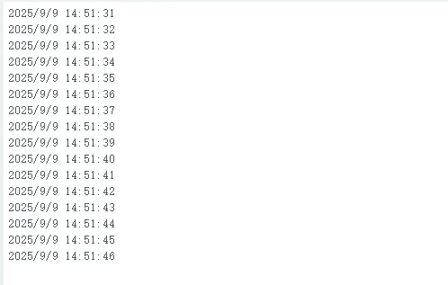
rtc_init(): Initializes the clock module.i2c_rtc_setTime(2025, 9, 9, 14, 51, 30): Writes the demonstration time on each startup.i2c_rtc_loop_task: Reads the RTC date and time and outputs them through the serial port every second.
Running Effect
After uploading, the serial port time starts from September 9, 2025, 14:51:30 and increments every second; the screen does not light up. Each reset rewrites this demonstration time, with no network time synchronization.
To change the starting date and time, adjust i2c_rtc_setTime() in the sketch and upload again. To test the RTC running continuously, you can remove the call that sets the time.
05_shtc3
Example Description
Reads the onboard SHTC3 temperature and humidity sensor via I2C, verifies the data, and outputs the ambient temperature and relative humidity.
Hardware Connection
Connect the development board to the computer with a USB data cable; no external sensor is required.
Code Analysis
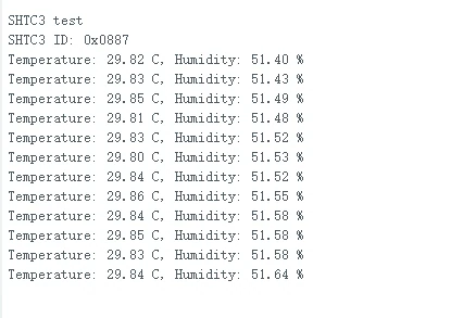
setup(): Initializes I2C using GPIO6 (SDA) and GPIO7 (SCL), resets the sensor, and reads the device ID.readShtc3(): Wakes up the sensor, sends the measurement command, reads the temperature and humidity data and performs a Cyclic Redundancy Check (CRC), then converts the data to Celsius temperature and relative humidity.loop(): Calls the read function and outputs the measurement results or error messages at intervals of about 1 second.
Running Effect
After uploading, the serial port displays the temperature and relative humidity about once per second, and the screen does not light up. Sensor readings include a CRC check; if it reports that the sensor cannot be found or that reading failed, power cycle the device and check the serial port errors.
06_lvgl_demo
Example Description
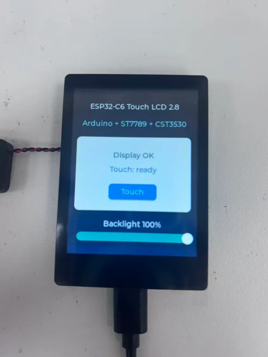
Uses LVGL 8 to create a display and touch test interface, verifying screen functionality with the ST7789 display driver, CST3530 touch driver, and backlight adjustment.
Hardware Connection
Connect the development board to the computer using a USB data cable; no TF card or speaker is required.
Code Analysis
setup(): Initializes the CH32V003, LCD, and touch controller, allocates the drawing buffer, and registers the LVGL display and input devices.display_flush(): Sends the LVGL drawing data to the LCD and notifies LVGL when complete.touch_read(): Reads the touch coordinates and updates the input state and the interface coordinate label.brightness_slider_event_cb(): Responds to slider changes and callsSet_Backlight()to set the backlight.loop(): Updates the LVGL time base and executeslv_timer_handler()to handle interface refresh and interaction.
Running Effect
After uploading, the LCD displays Display OK and the touch status. Touch the screen and the coordinates update with the touch position; drag the bottom slider to adjust the backlight between 5% and 100%.
Use the bundled LVGL 8.4.0 and libraries/lv_conf.h, keeping the LV_COLOR_DEPTH 16 and LV_COLOR_16_SWAP 0 settings. The display driver is ST7789 and the touch driver is CST3530; the example is already adapted, so no additional GFX or other touch libraries need to be installed.
07_battery_voltage
Example Description
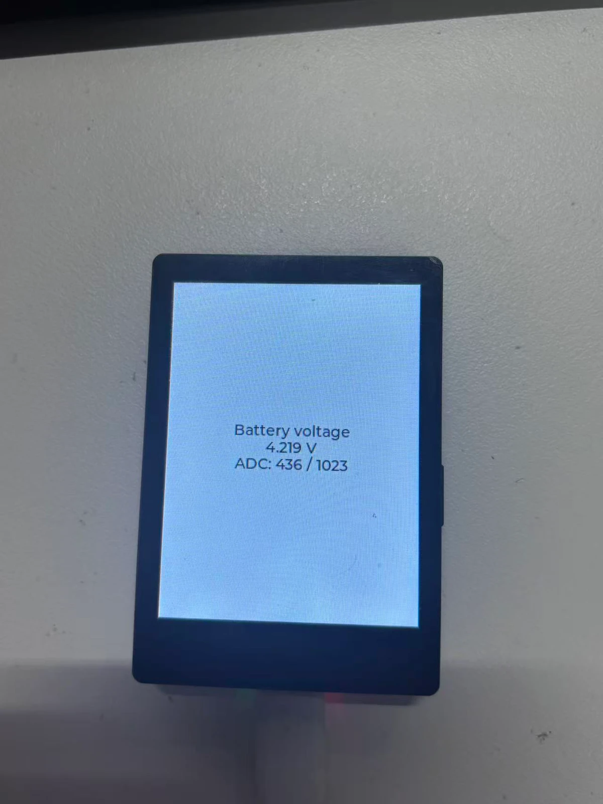
Reads the battery ADC sample value through the CH32V003, converts it to voltage, and displays it on the LCD and in the serial port.
Hardware Connection
Connect a battery that matches the development board; verify the positive and negative terminals before connecting, then connect to the computer using a USB data cable.
Code Analysis
setup(): Waits for the CH32V003 to initialize successfully, then initializes the LCD and LVGL, creates the voltage display label, and turns on the backlight.Board_ReadBatteryVoltage(): Reads eight ADC samples and averages them, and converts the battery voltage based on a nominal 3.3 V reference voltage and a 3:1 voltage divider.loop(): Reads the data once per second and updates the label and serial output; displaysADC read failedif reading fails.
Running Effect
After uploading, the LCD and serial port update the battery voltage and the raw ADC value (0 to 1023) about once per second. This displays an estimated voltage, not the remaining battery percentage.
If no battery is connected or the contact is poor, the reading may be zero or abnormal. The calculation uses a nominal 3.3 V ADC reference voltage and a 3:1 voltage divider; if you need to verify accuracy, compare with a multimeter.

Troubleshooting
- Library files not found: Check whether the project folder points to
examples/arduino, confirm that the bundledlibrariesandlv_conf.hare complete, and then restart the IDE.lvgl.hcorresponds tolvgl, andSensorPCF85063.hppcorresponds toSensorLib. - LVGL interface errors: Confirm that the bundled LVGL 8.4.0 is installed, and avoid mistakenly using LVGL 9 or other libraries with the same name.
- Blank screen: First check the example list; the serial port sensor and TF card identification examples do not light up the screen. If a display example behaves abnormally, check the serial output for the initialization results of the LCD, touch, and CH32V003.
- Upload failure or no serial output: Check the data cable and serial port selection, close other software that is occupying the serial port, and press RESET to retry; use 115200 baud for the serial monitor.
For more questions, see the ESP32-C6-Touch-LCD-2.8 FAQ.