Working with ESP-IDF
This section describes how to build, flash, operate, and observe the behavior of the ESP-IDF basic examples. Prepare the development board and USB data cable, and download the ESP32-C6-Touch-LCD-2.8 Example Programs.
This chapter includes the following sections. Please read as needed:
ESP-IDF Getting Started
New to ESP32 ESP-IDF development and looking to get started quickly? We have prepared a general Getting Started Tutorial for you.
- Section 1: Environment Setup
- Section 2: Running Examples
- Section 3: Creating a Project
- Section 4: Using Components
- Section 5: Debugging
- Section 6: FreeRTOS
- Section 7: Peripherals
- Section 8: Wi-Fi Programming
- Section 9: BLE Programming
Please Note: This tutorial uses the ESP32-S3-Zero as a teaching example, and all hardware code is based on its pinout. Before you start, it is recommended that you check the pinout of your development board to ensure the pin configuration is correct.
Set Up the ESP-IDF Development Environment
Please refer to Install ESP-IDF Development Environment to install the environment.
This document uses ESP-IDF v5.5.4. There are 8 basic examples in total, located in examples/esp-idf. The graphical interface uses LVGL 9.5.0, which is different from the LVGL 8.4.0 used by the Arduino examples.
The following guide uses Windows as an example, demonstrating development using VS Code + the ESP-IDF extension. macOS and Linux users should refer to the official documentation.
The screenshots in this section use ESP-IDF V5.5.2 as an example. When installing, please select the ESP-IDF version that matches your board's example.
Install the ESP-IDF Development Environment
-
Download the installation manager from the ESP-IDF Installation Manager page. This is Espressif's latest cross-platform installer. The following steps demonstrate how to use its offline installation feature.
Click the Offline Installer tab on the page, then select Windows as the operating system and the ESP-IDF version you need (the version shown in the screenshot is for reference only — choose the version that fits your actual needs).
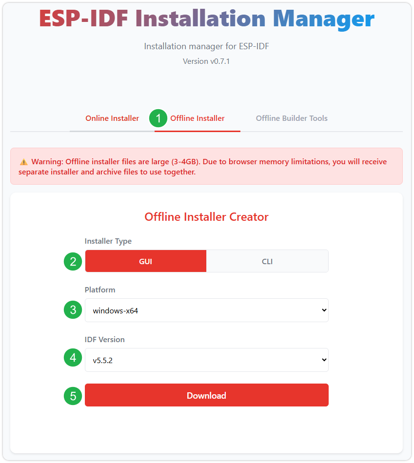
After confirming your selection, click the download button. The browser will automatically download two files: the ESP-IDF Offline Package (.zst) and the ESP-IDF Installer (.exe).
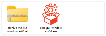
Please wait for both files to finish downloading.
-
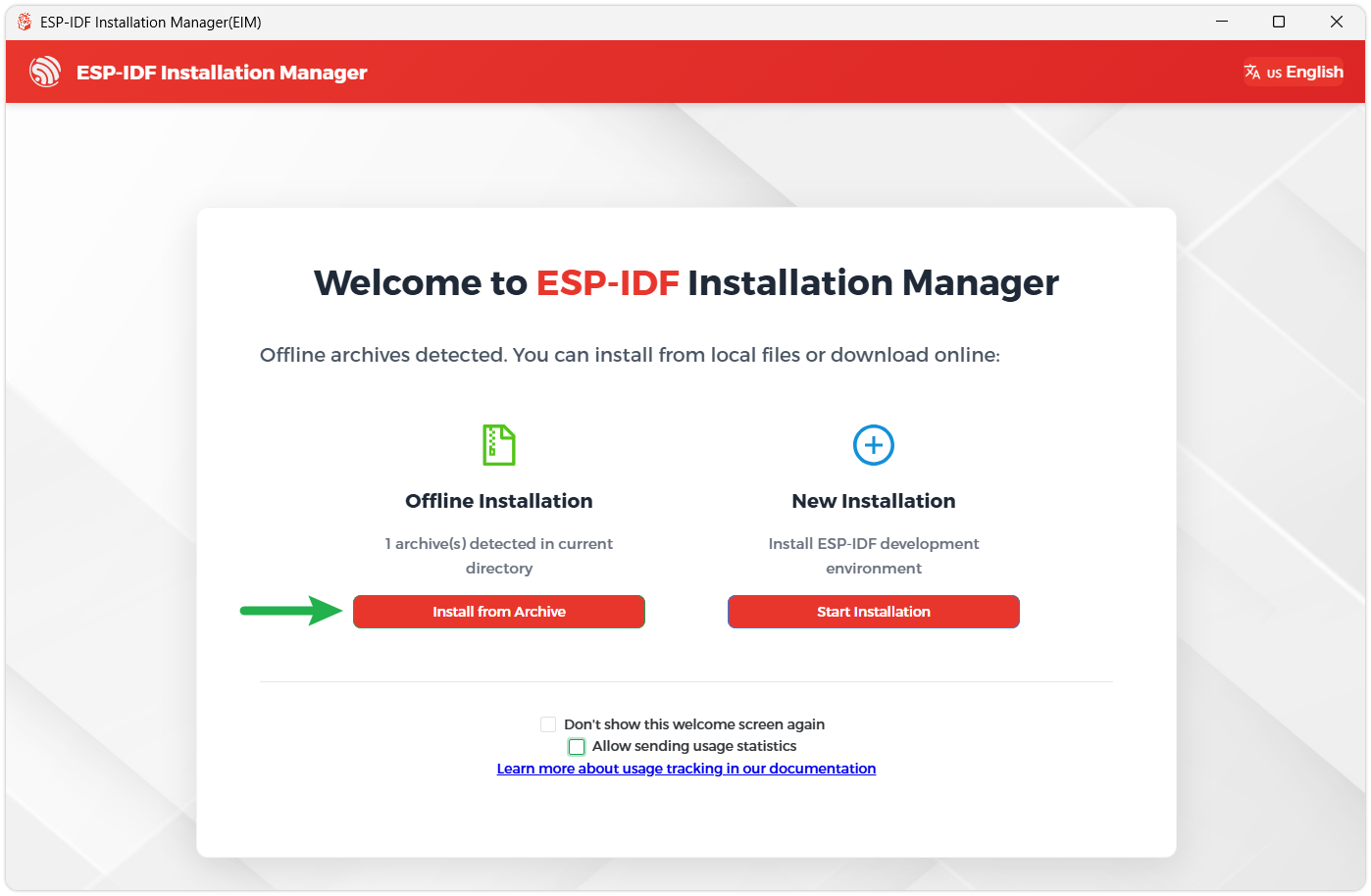
Once the download is complete, double-click to run the ESP-IDF Installer (eim-gui-windows-x64.exe).
The installer will automatically detect if the offline package exists in the same directory. Click Install from archive.
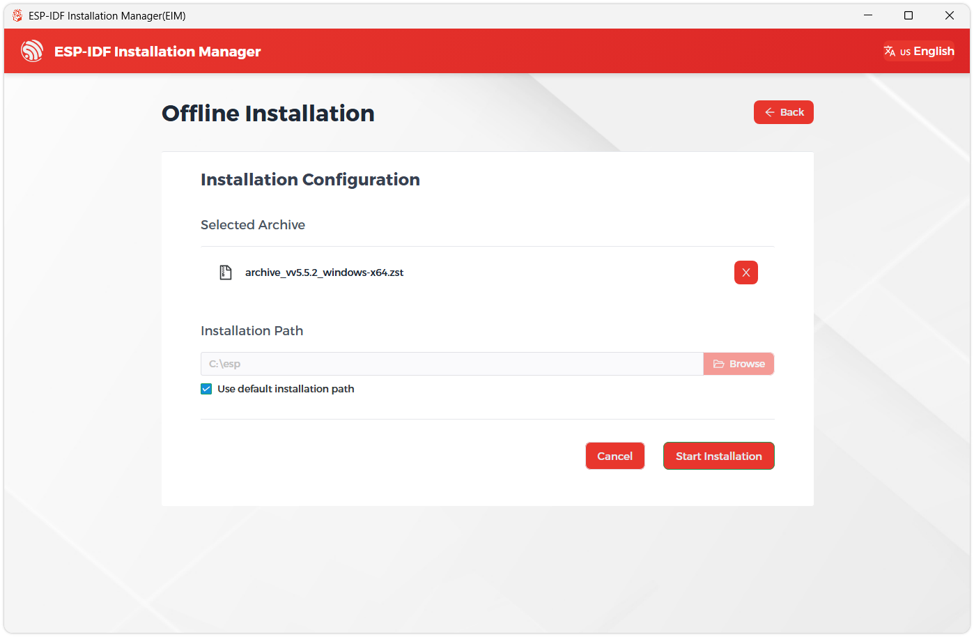
Next, select the installation path. We recommend using the default path. If you need to customize it, ensure the path does not contain Chinese characters or spaces. Click Start installation to proceed.
-
When you see the following screen, the ESP-IDF installation is successful.
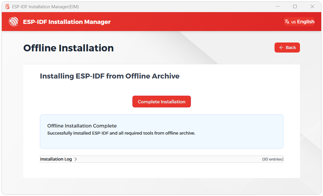
-
We recommend installing the drivers as well. Click Finish installation, then select Install driver.
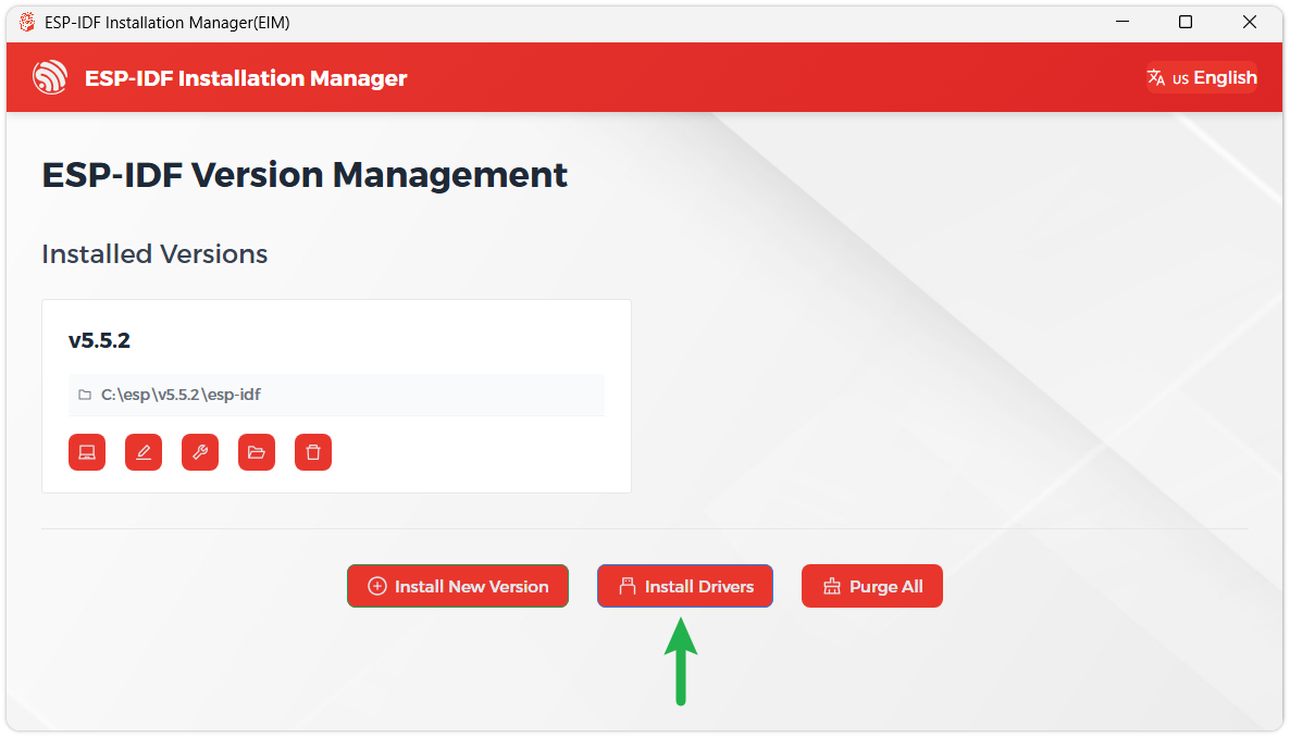
Install Visual Studio Code and the ESP-IDF Extension
-
Download and install Visual Studio Code.
-
During installation, it is recommended to check Add "Open with Code" action to Windows Explorer file context menu to facilitate opening project folders quickly.
-
In VS Code, click the Extensions icon
 in the Activity Bar on the side (or use the shortcut Ctrl + Shift + X) to open the Extensions view.
-
Enter ESP-IDF in the search box, locate the ESP-IDF extension, and click Install.
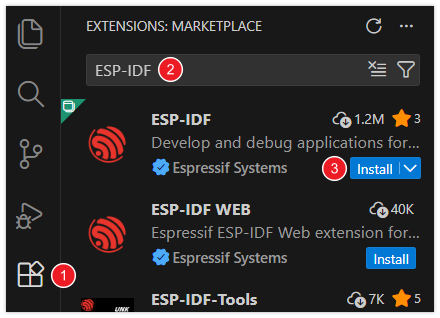
-
For ESP-IDF extension versions ≥ 2.0, the extension will automatically detect and recognize the ESP-IDF environment installed in the previous steps, requiring no manual configuration.
| Environment or Component | Version or Configuration | Description |
|---|---|---|
| ESP-IDF | v5.5.4 | Use the SDK version consistent with the project |
| Target Chip | esp32c6 | Already set in the project; no need to change the target |
| LVGL | 9.5.0 | Managed by the project dependency configuration |
| Board Support Package | components/esp32_c6_touch_lcd_2_8 | Included with each example, containing display, touch, and onboard peripheral adaptation |
| Serial Baud Rate | 115200 | Used for basic example logs |
The development board is equipped with 16 MB Flash and no PSRAM. Use the memory and partition configuration provided with the project.
The required components are downloaded according to the project's dependency configuration on the first build. Please keep the original component configuration and dependency lock files, and do not copy Arduino library files into the ESP-IDF project.
Build and Flash
-
In VS Code, select the installed ESP-IDF v5.5.4 environment.
-
Open the directory of a single example to run, for example
examples/esp-idf/01_lvgl_demo. The directory should containCMakeLists.txt, and the project has already set the target chip to ESP32-C6. -
Connect the development board via USB, and open the ESP-IDF terminal in that example directory.
-
Run the following commands to build, flash, and view the serial logs, replacing
COM5with the actual serial port:idf.py buildidf.py -p COM5 flash monitor -
The serial monitor uses a 115200 baud rate. After flashing, check the results as described below, and press
Ctrl+]to exit the monitor.
Each example comes with its own Board Support Package (BSP) and local drivers, and can be used by copying the complete single example directory; keep its components, configuration files, and dependency lock files.
After flashing a basic example, the development board runs that example. Complete APPs such as Weather, Music Player, Xiaozhi AI, and 2048 are located in the independent factory project examples/factory. To run the APP desktop, compile and flash that factory project.
Example Programs
The examples are located in the examples/esp-idf directory of the source package. Each of the following examples is an independent project; after opening the corresponding directory, run it according to the steps in Build and Flash.
| Example Directory | Function | View Result |
|---|---|---|
| 01_lvgl_demo | LVGL widgets display and touch | LCD |
| 02_sd_card | Write, read back, and verify the TF card test file | LCD, serial port |
| 03_qmi8658 | Three-axis acceleration and angular velocity | Serial port |
| 04_pcf85063 | RTC setting and reading | Serial port |
| 05_shtc3 | Temperature and humidity reading with CRC verification | Serial port |
| 06_exio | EXIO6/7 level and backlight PWM switching | Serial port, level and backlight changes |
| 07_audio | Touch recording, level monitoring, and playback | LCD, speaker |
| 08_battery_voltage | Battery voltage and raw ADC value | LCD, serial port |
01_lvgl_demo
Program Description
Initializes the screen and touch through the Board Support Package and runs the LVGL 9 widgets demonstration.
Hardware Connection
Connect the development board to the computer using a USB data cable; no TF card or speaker is required.
Code Analysis
bsp_display_start(): Initializes the display, touch, and LVGL runtime environment.bsp_display_lock()andbsp_display_unlock(): Protect LVGL operations when creating widgets.lv_demo_widgets(): Creates the widgets demonstration interface; then callsbsp_display_show()to turn on the screen after the first frame is complete.
Expected Behavior
After building and flashing, the screen lights up after the first frame is complete and displays the LVGL widgets demonstration page. Tap widgets and drag sliders to check whether touch interaction works properly; press RESET to restart the demonstration.
If the screen stays off, check whether the serial port reports errors in LCD, touch, or backlight initialization.
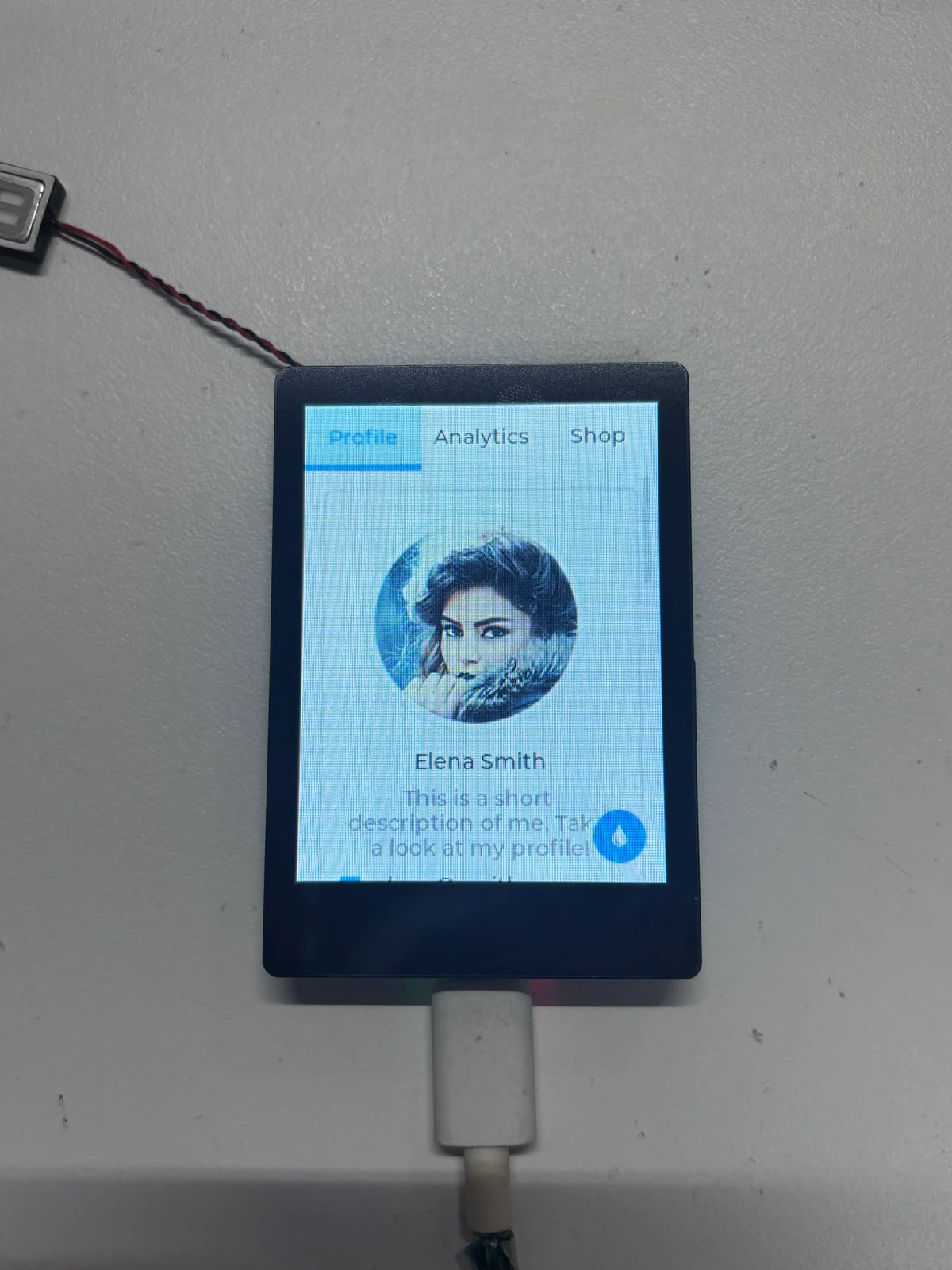
02_sd_card
Program Description
Writes a test file to the TF card, reads it back and compares the content, and displays the test result on the serial port and LCD.
Hardware Connection
Each run overwrites test.txt in the root directory of the TF card. Please back up any file with the same name first, and use a FAT32-format test card. This IDF example does not format the TF card.
Insert the TF card before powering on, then connect the development board to the computer with a USB data cable; there is no need to create a test file in advance.
Code Analysis
run_sd_test(): Mounts the TF card throughbsp_sdcard_acquire(), writestest.txtin overwrite mode, then reads the file and compares the length and content.- After the test is complete, releases and unmounts the TF card, retaining the file for viewing on a computer.
show_result(): Creates the LVGL result interface, displaying the status, file path, and read-back content. TF card access is completed before LCD initialization, to avoid occupying the SPI bus shared by both at the same time.
Expected Behavior
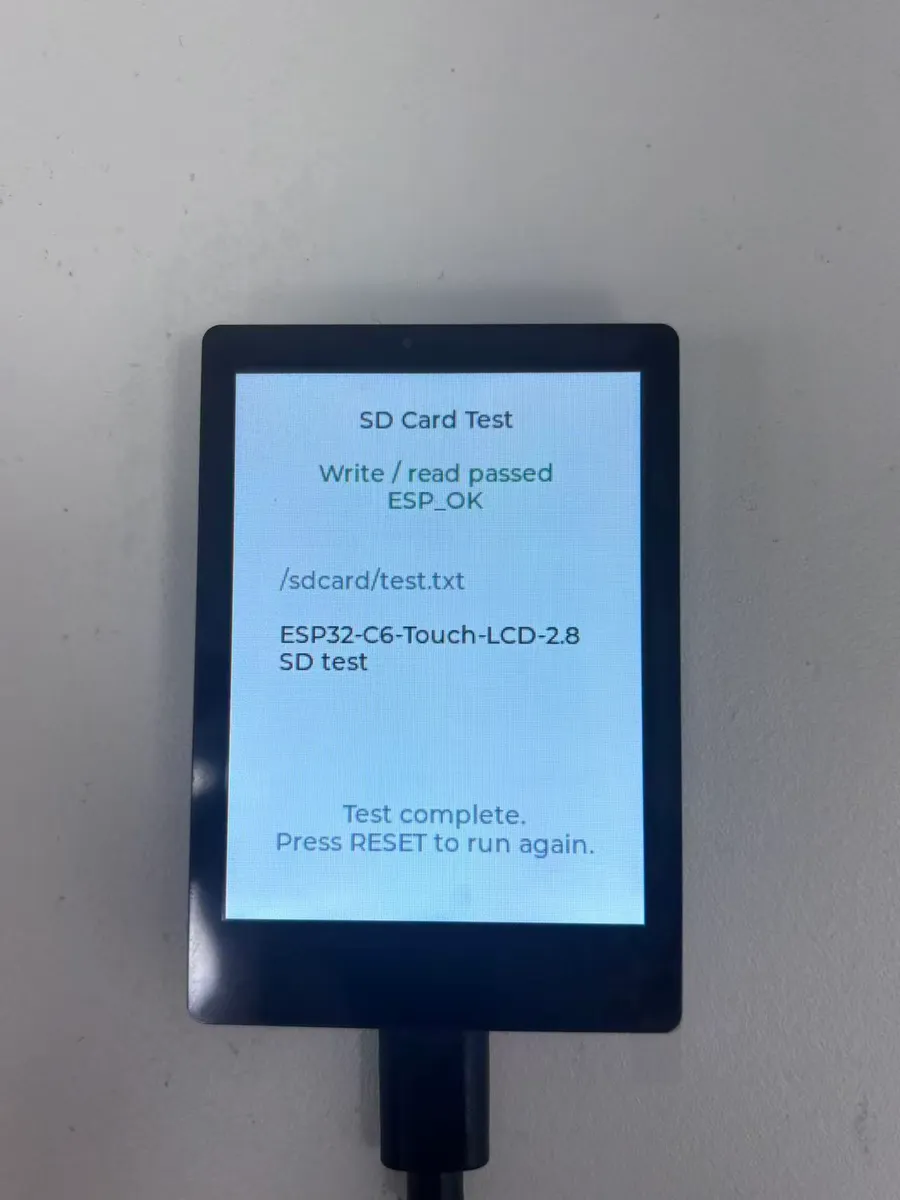
The program first writes the test content to the TF card, then reads it back and verifies it, and finally turns on the screen to display the result. On success:
-
The serial port outputs
SD card mounted,Write successful,Read successfulandWrite/read verification: ESP_OKin sequence. -
The screen displays
Write / read passed, the file path/sdcard/test.txt, and the following read-back content:ESP32-C6-Touch-LCD-2.8 SD test
After verification is complete and the TF card is successfully unmounted, the screen retains the result, and you can remove the card to view test.txt in the root directory on a computer. Press RESET to test again.
If no card is inserted or mounting fails, the screen displays SD card not mounted; insert a FAT32 card and press RESET to retry. If writing, reading, or verification fails, check the corresponding step based on the on-screen prompt and serial logs.
A standalone cmd=5 ... command not supported does not mean the test failed. This command is used to probe SDIO functions, and ordinary storage cards may not support it; the subsequent mount, write, and read-back verification results should be used as the basis.
03_qmi8658
Program Description
Reads the onboard QMI8658 six-axis sensor and outputs three-axis acceleration and angular velocity through the serial port.
Hardware Connection
Connect the development board to the computer with a USB data cable; no external sensor is required.
Code Analysis
bsp_imu_init(): Initializes the motion sensor.bsp_imu_get_data(): Reads three-axis acceleration and angular velocity, outputs the data on success, and prints the error code on failure.- The main loop sets a read interval of about 500 ms through
vTaskDelay().
Expected Behavior
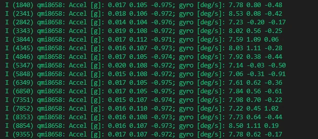
The serial port outputs the three-axis acceleration Accel [g] and angular velocity gyro [deg/s] about every 500 ms. Gently tilt or rotate the development board, and the data changes accordingly; gravity is still measured when stationary, so each axis is not necessarily zero.
This example does not initialize the LCD, so a black screen is normal.
04_pcf85063
Program Description
Sets the onboard PCF85063 real-time clock (RTC) and periodically reads the date and time through the serial port.
Hardware Connection
Connect the development board to the computer using a USB data cable; no external clock module is required.
Code Analysis
bsp_rtc_init(): Initializes the RTC.initial: Stores the demonstration time at startup;bsp_rtc_set_datetime()writes it to the RTC.bsp_rtc_get_datetime(): Reads the date and time in a loop, outputting about once per second.
Expected Behavior
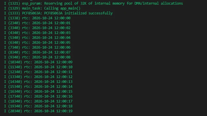
At startup, the onboard RTC is set to October 24, 2026, 12:00:00, and the serial port outputs the date and time once per second, with the seconds continuing to increase. This example does not light up the screen.
The demonstration time is written again on every reset, and no network time synchronization is performed. To modify the start date, adjust initial in main/main.c and recompile and flash.
05_shtc3
Program Description
Reads the ambient temperature and relative humidity of the onboard SHTC3, verifies the data, and outputs it through the serial port.
Hardware Connection
Connect the development board to the computer with a USB data cable; no TF card or external sensor is required.
Code Analysis
bsp_environment_init(): Initializes the temperature and humidity sensor.bsp_environment_get_data(): Reads the temperature and humidity, and the underlying driver performs a Cyclic Redundancy Check (CRC).- The main loop reads once per second, outputting the temperature in Celsius and the relative humidity on success, and outputting the error code on failure.
Expected Behavior
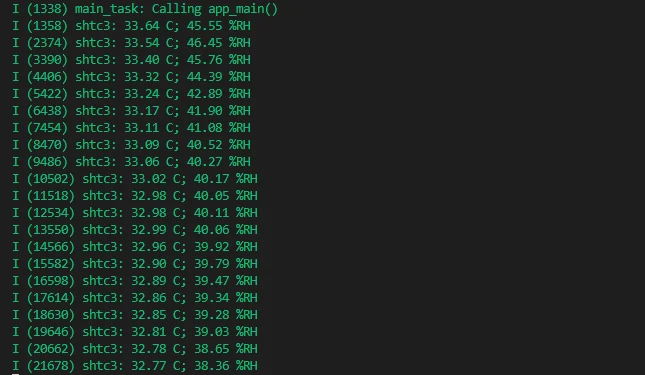
The serial port outputs the ambient temperature and relative humidity about once per second, for example 25.00 C; 50.00 %RH. The CRC of the data returned by the sensor is verified when reading. This example does not light up the screen.
If an I2C or CRC error occurs, power on again and check the log; when measuring ambient temperature and humidity, do not cover or wet the sensor.
06_exio
Program Description
Controls the EXIO6/7 output levels and the backlight Pulse Width Modulation (PWM) value through the onboard CH32V003.
Hardware Connection
Connect the development board to the computer using a USB data cable; you can use a multimeter to measure the voltage of the EXIO6/7 header pins relative to GND.
Code Analysis
bsp_io_expander_init(): Initializes the IO expander, then obtains the control handle.esp_io_expander_set_dir(): Configures only EXIO6/7 as outputs.esp_io_expander_set_level()andcustom_io_expander_set_pwm(): Toggle the output level and backlight PWM every second, and print the status through the serial port.
Expected Behavior
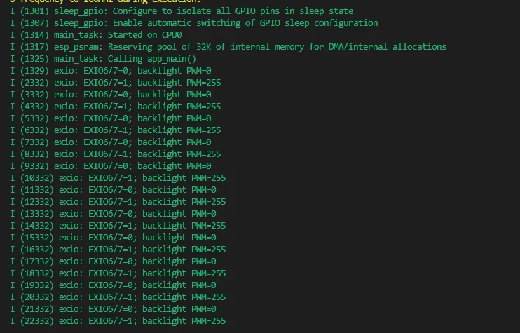
After running, it toggles the EXIO6/7 outputs every second and switches the backlight between PWM 0 and 255. The serial port displays alternately:
EXIO6/7=0; backlight PWM=0
EXIO6/7=1; backlight PWM=255
The backlight brightness switching is expected behavior, and the LCD does not display the application interface. The CH32V003 is preloaded with control firmware and does not need to be flashed separately; this example only uses EXIO6/7 for testing, and other expansion IOs are used for onboard devices, so do not toggle them arbitrarily.
07_audio
Program Description
Monitors the microphone level through the touch interface and supports recording, stopping, and playback. The recording is temporarily stored in a dedicated SPIFFS partition in the onboard Flash, with no TF card or network required.
Hardware Connection
Connect a matching speaker before powering on, then connect the development board to the computer with a USB data cable.
Code Analysis
main/main.cpp: Initializes the display, callsMicTest::init()andMicTest::run()to create the recording interface and start the background task.MicTest::event(): Responds to the record, stop, and play buttons.MicTest::work(): Captures microphone PCM data, calculates the level, and records or plays back according to the current state; writes up to 10 seconds of recording to a temporary Flash file throughRecordingStore.MicTest::refresh(): Updates the volume bar, status, and duration display.RecordingStore: Reads and writes/recording/mic.pcmin therecordingpartition, avoiding allocating a full recording buffer on the C6, which has no PSRAM.
Expected Behavior
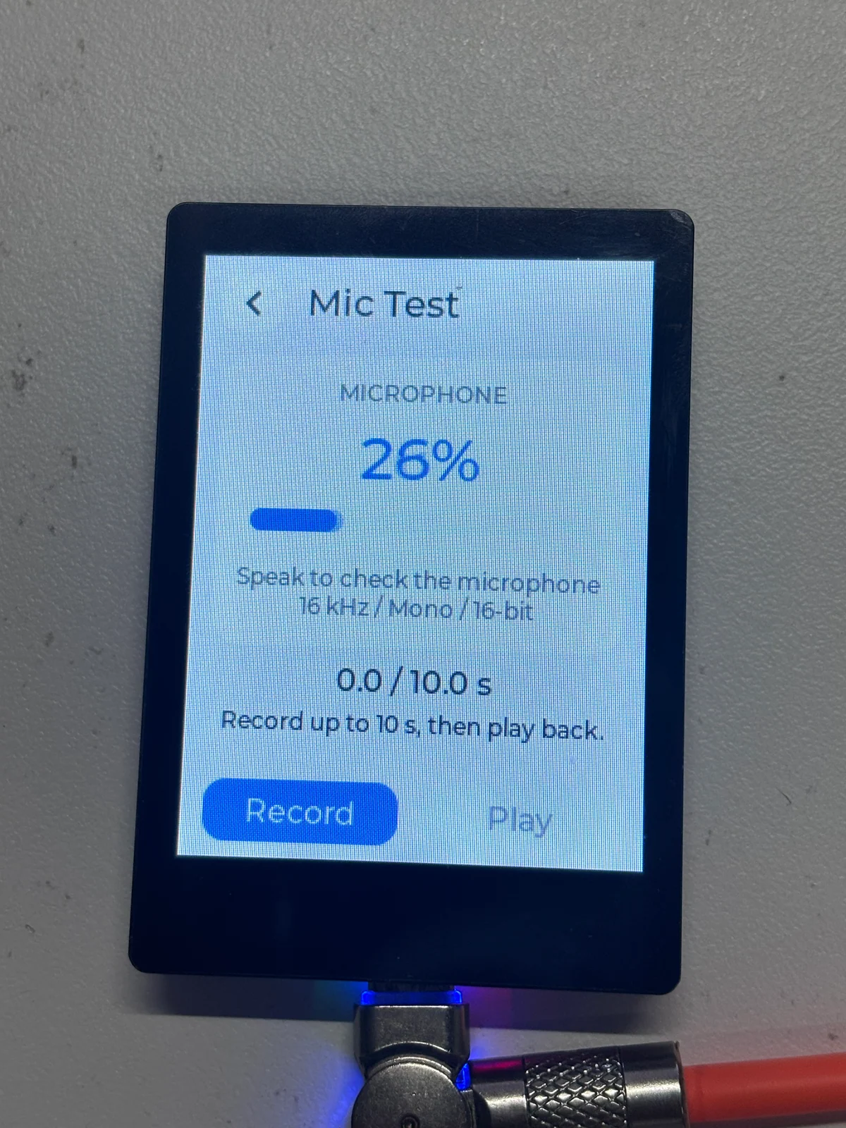
This standalone example follows the touch operation of the factory Mic Test. After startup, experience it with the following steps:
- Speak into the onboard microphone and observe changes in the volume bar and level percentage.
- Tap "Record" to start recording; the screen displays
RECand the elapsed recording time. - Tap "Stop" to end early, or wait until the full 10 seconds have been recorded and it stops automatically.
- Tap "Play" to play back the recording; during playback, you can tap "Stop" to abort, and after it ends, you can play it back again.
The recording parameters are 16 kHz, mono, 16-bit, and the default playback volume is 100/100. The recording is temporarily written to the onboard Flash, and a new recording overwrites the previous one. The previous recording is not restored after a reset or power loss, and the example does not provide a file export function. Please keep the recording partition in the project's built-in partition table.
The "Play" button is unavailable when no recording has been made. The speaker stays muted during level monitoring and does not output the microphone sound in real time. If there is no sound during playback, check the speaker connection, recording duration, and on-screen error prompts.
08_battery_voltage
Program Description
Obtains the battery ADC sampling value through the CH32V003, converts it to voltage, and displays it on the LCD and serial port.
Hardware Connection
Connect a matching battery to the battery holder, verify the polarity before connecting, and then connect to the computer with a USB data cable.
Code Analysis
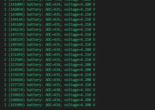
app_main(): Initializes the IO expander and display, creates the voltage label, and then reads the data in a loop.bsp_battery_get_voltage(): Reads the ADC data eight times and averages them, and calculates the battery voltage using the nominal 3.3 V reference voltage and 3:1 voltage divider.- Updates the LCD and serial output every second; uses the display lock when updating the label, and displays
ADC read failedwhen reading fails.
Expected Behavior
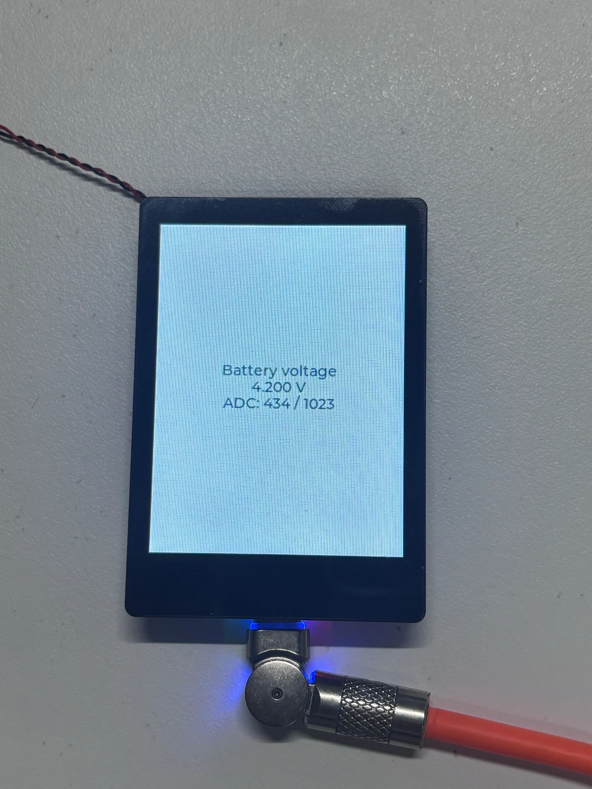
The LCD and serial port update the estimated battery voltage and raw ADC value about once per second. The screen displays Battery voltage, the voltage, and ADC: ... / 1023; it displays voltage, not the remaining battery percentage.
If no battery is connected or the contact is poor, the reading may be zero or abnormal. The program averages eight ADC samples and uses the nominal 3.3 V reference voltage and 3:1 voltage divider; if you need to verify accuracy, you can compare with a multimeter.
Troubleshooting
- Compilation errors after switching IDF: Confirm that the current terminal uses v5.5.4, run
idf.py fullclean, and then build again; do not reuse build caches generated by other IDF versions. - No serial output: Check the USB data cable, serial port selection, and 115200 baud rate, close other software that is occupying the serial port, and then press RESET.
- Screen stays off: First refer to the example list to confirm whether the example has a display interface; the sensor serial examples do not turn on the screen.
For more questions, see the ESP32-C6-Touch-LCD-2.8 FAQ.