Working with ESP-IDF
This chapter contains the following sections. Please read as needed:
- ESP-IDF Getting Started
- Setting Up the Development Environment
- Running Official Espressif Examples
- Erasing Device Flash
ESP-IDF Getting Started
New to ESP32 ESP-IDF development and looking to get started quickly? We have prepared a general Getting Started Tutorial for you.
- Section 1: Environment Setup
- Section 2: Running Examples
- Section 3: Creating a Project
- Section 4: Using Components
- Section 5: Debugging
- Section 6: FreeRTOS
- Section 7: Peripherals
- Section 8: Wi-Fi Programming
- Section 9: BLE Programming
Please Note: This tutorial uses the ESP32-S3-Zero as a teaching example, and all hardware code is based on its pinout. Before you start, it is recommended that you check the pinout of your development board to ensure the pin configuration is correct.
Setting Up the Development Environment
The following tutorial is based on the Windows development environment using VS Code.
Note: ESP-IDF supports ESP32-C6 starting from version V5.1. ** When installing ESP-IDF, you must select version V5.1 or later.**
Please refer to Waveshare ESP-IDF Getting Started - Section 1 Set Up Environment to complete the ESP-IDF development environment configuration.
Running Official Espressif Examples
Official Example Usage Tutorial
Creating an Example
-
Use the shortcut F1 and enter:
esp-idf:show examples projects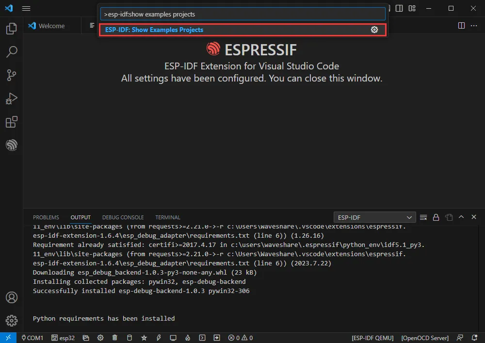
-
Select your current IDF version
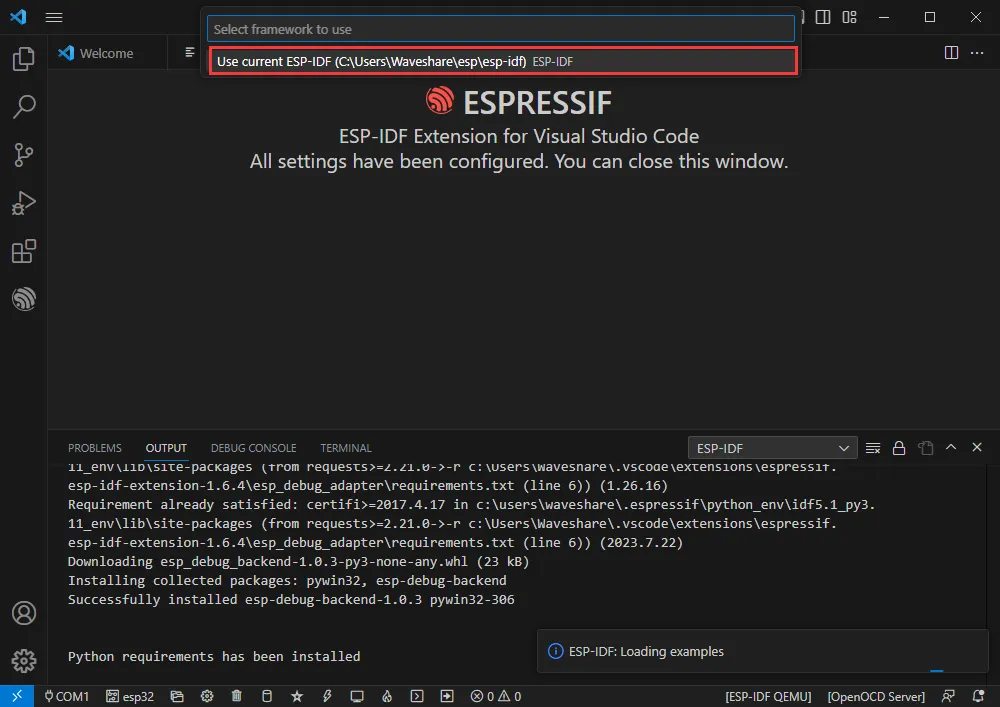
-
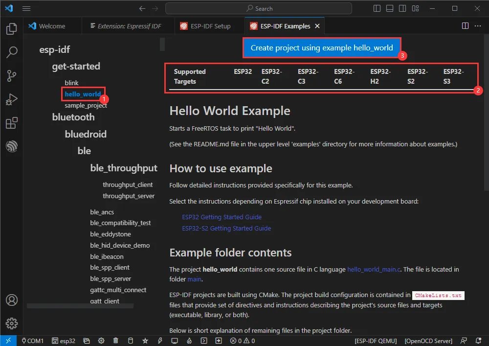
Using the Hello World example:
- ① Select the corresponding example
- ② Its readme will indicate which chips the example supports (the usage and file structure are described there, omitted here)
- ③Click to create the example
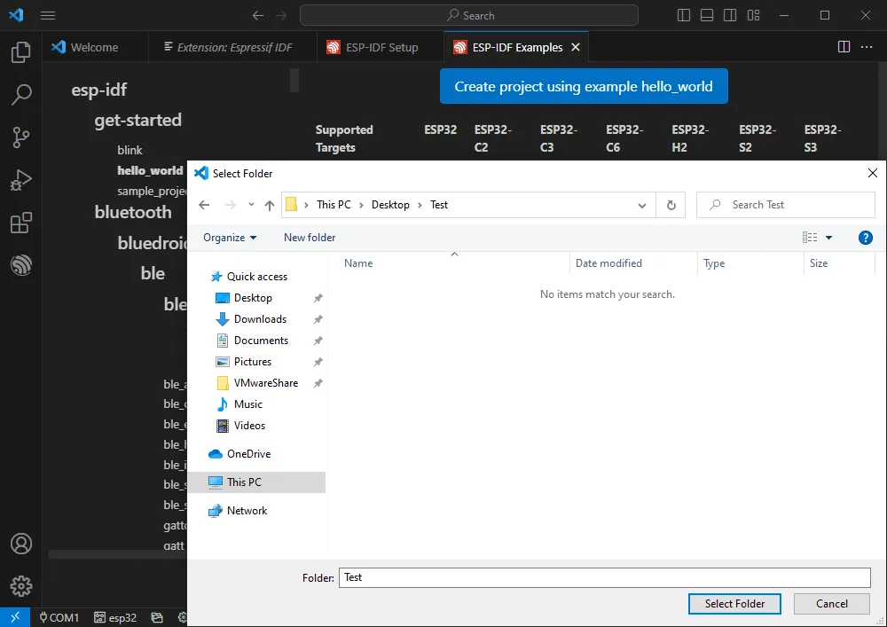
 Choose the path to place the example; the folder name must not already exist
Changing the COM Port
-
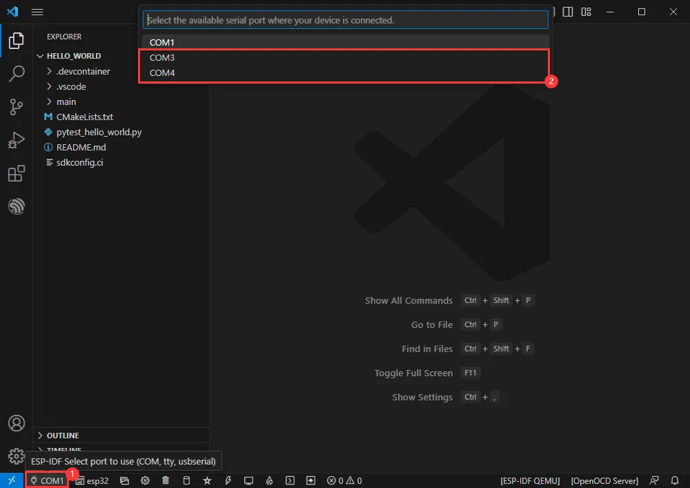
This shows the COM port in use. Click to change it.
-
Select the appropriate COM port for your device. It is recommended to use the USB COM port (can be checked in Device Manager).
-
If download fails, press and hold the reset button for more than 1 second, wait for the PC to re-detect the device, then try downloading again.
-
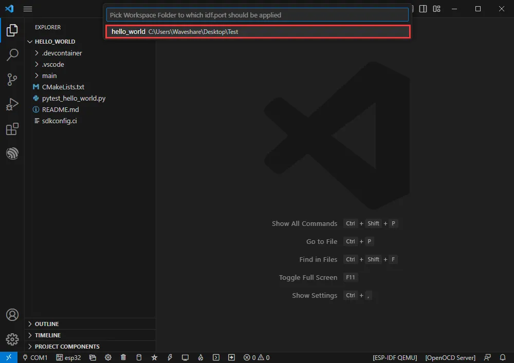
Select the project or example to use
-
The COM port is now changed.
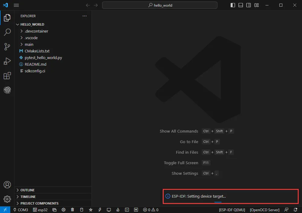
Changing the Target Driver
-
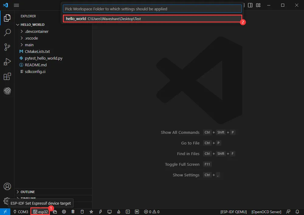
This shows the target driver in use. Click to change it.
-
Select the project or example to use
-
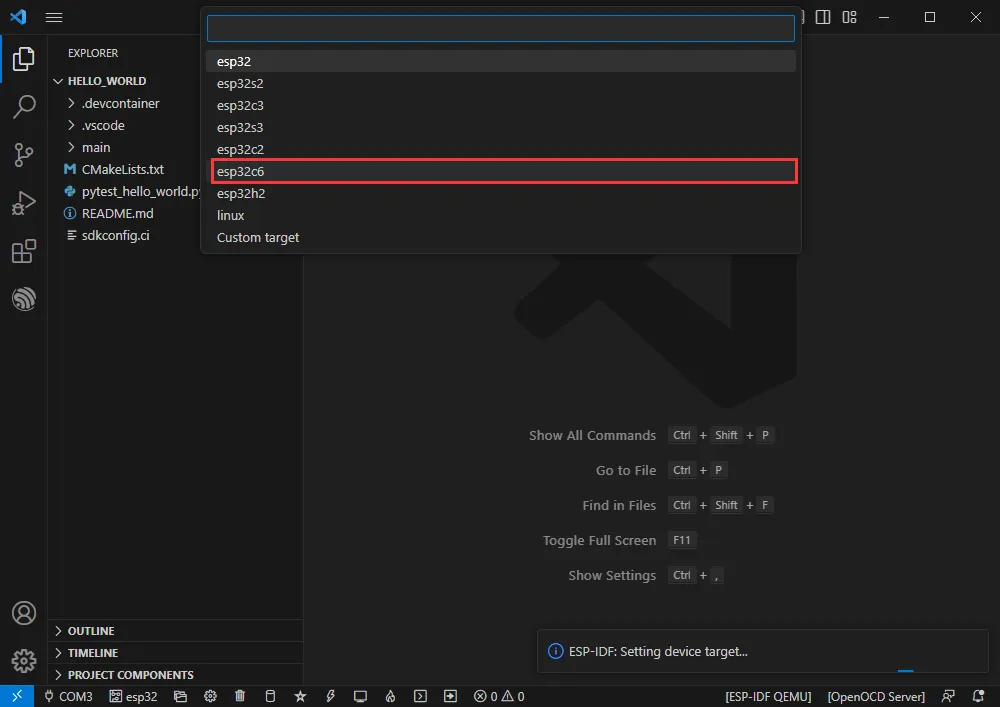
Wait a moment after clicking
-
Select the target we need to drive, namely the main chip ESP32-C6.
-
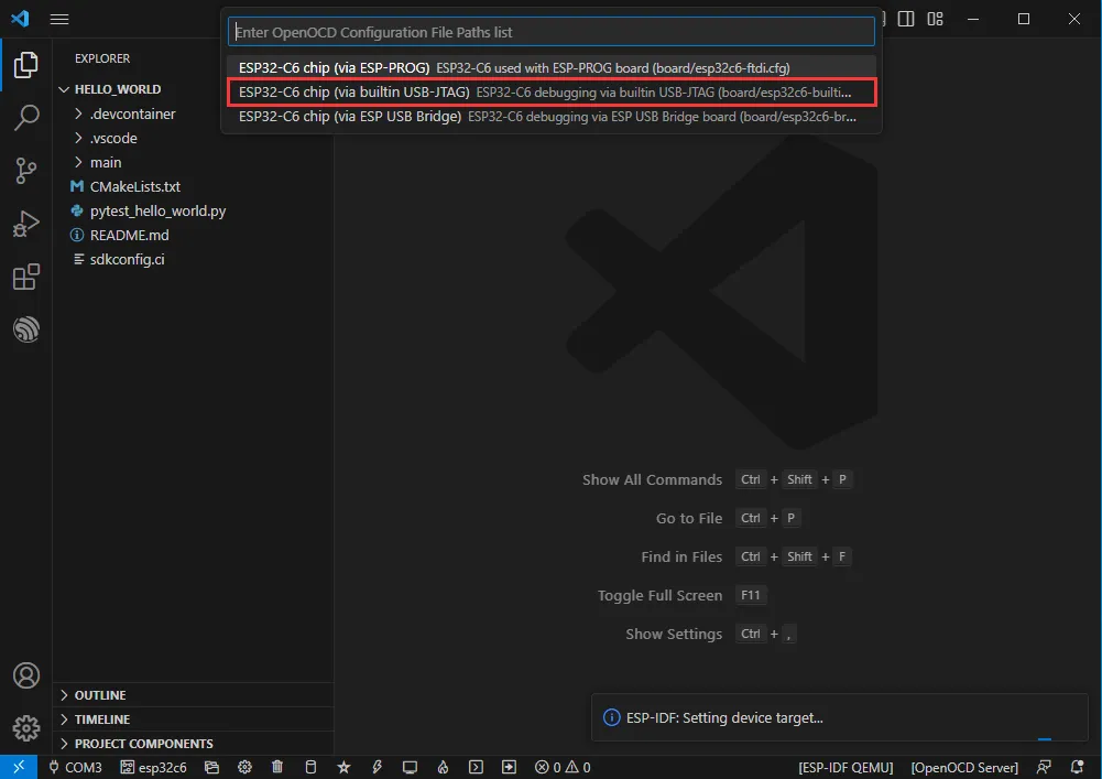
Select the openocd path. This does not affect us, so choose any.
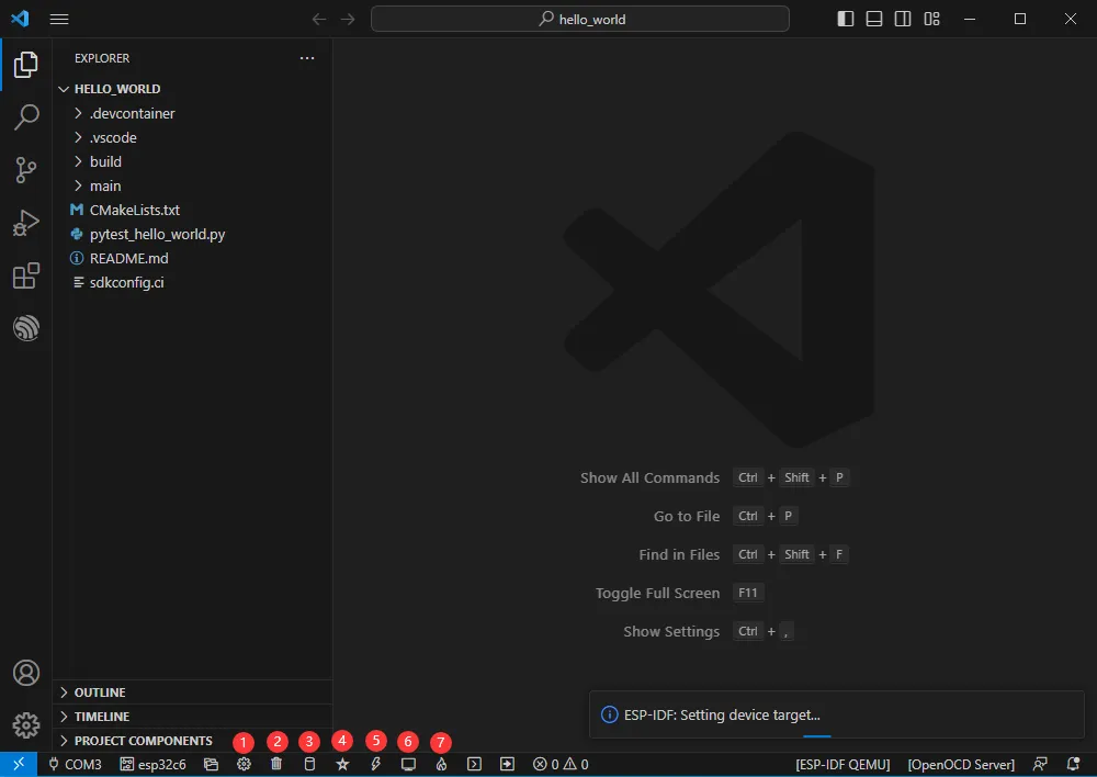
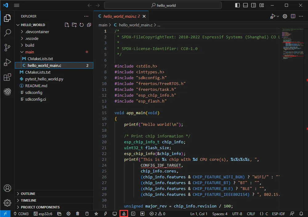
Other Status Bar Descriptions
- ① SDK Configuration Editor – many ESP-IDF features and configurations can be modified here.
- ② Full Clean – clean all build files.
- ③ Build
- ④ Current download method – defaults to UART.
- ⑤ Flash current firmware – do this after building.
- ⑥ Open Serial Monitor – to view serial output.
- ⑦ Build, Flash, and Open Serial Monitor combined button (most commonly used for debugging).
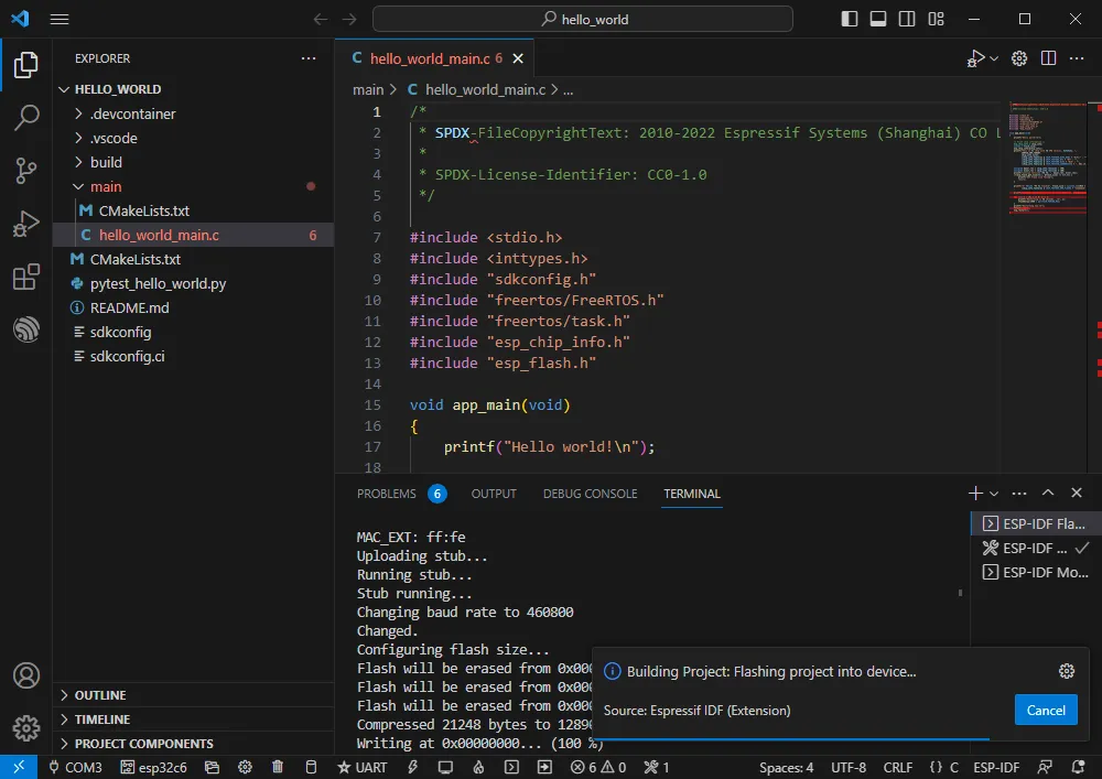
Build, Flash, Serial Monitor
-
Click the Build, Flash, Open Serial Monitor button described earlier.
-
Building may take a long time, especially on the first build.
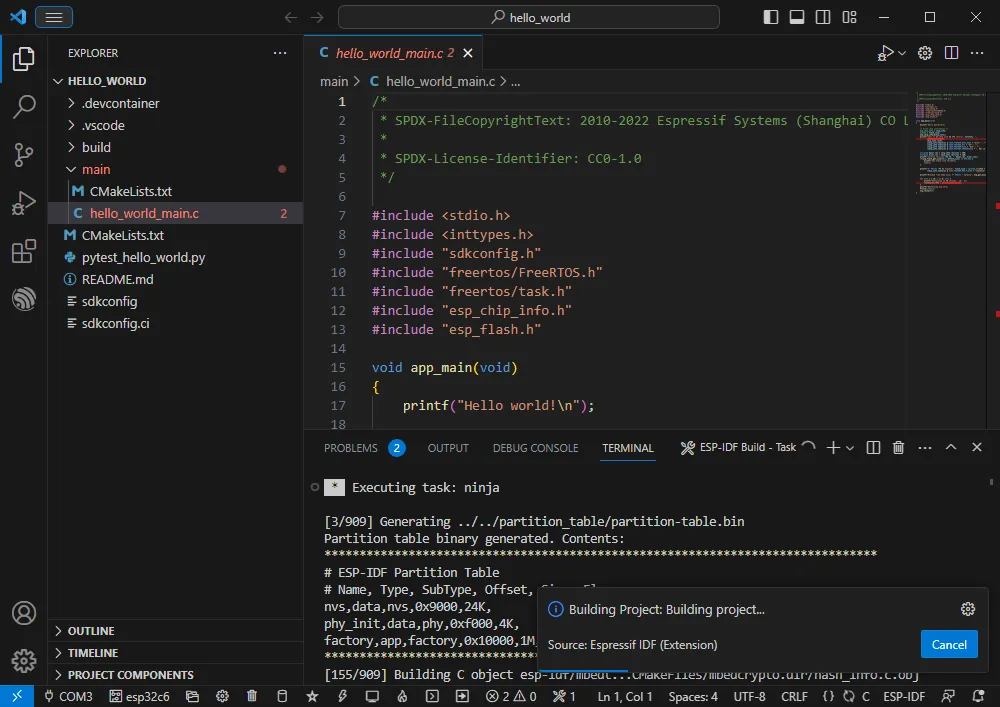
-
During this process, ESP-IDF may consume significant CPU resources and could cause system lag.
-
If flashing a new project for the first time, you will need to select the download method. Choose UART.
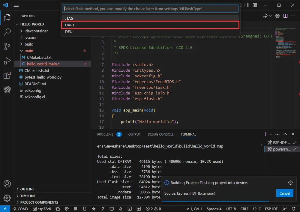
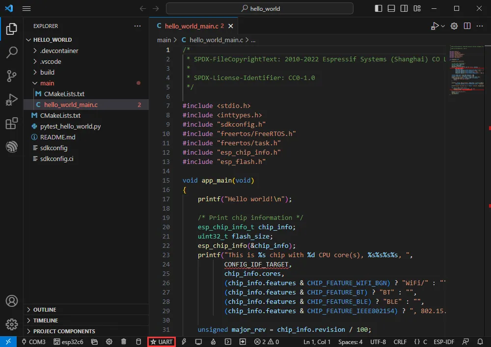
-
You can also change the Download Method later (click to pop up options).
-
Because the board has an automatic download circuit, no manual operation is needed; it will download automatically.
-
After successful download, the serial monitor opens automatically, showing the chip output and a prompt to restart after 10 seconds.
Example
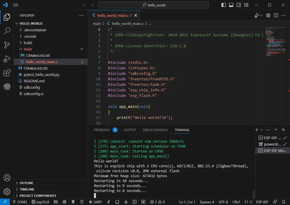
Hello Word
Official example path: get-started -> hello_world
Example effect: Output Hello world! in the TERMINAL window every 10 seconds.
Software Operation
- Create the official example hello_world following the tutorial above (Creating an Example).
- The program is compatible with ESP32-C6; no modification needed.
- Set the COM port and target driver correctly (it is recommended to use the USB COM port – check in Device Manager) , then click Build and Flash to run.
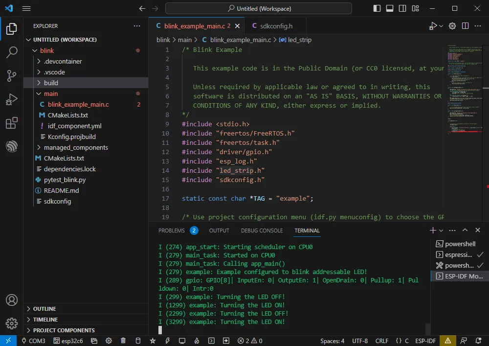
RGB
Official example path: get-started -> blink
Example effect: The onboard RGB LED blinks at 1-second intervals.
Software Operation
- Create the official example blink following the tutorial above (Creating an Example).
- The program is compatible with ESP32-C6; no modification needed.
- Set the COM port and target driver correctly (it is recommended to use the USB COM port – check in Device Manager) , then click Build and Flash to run.
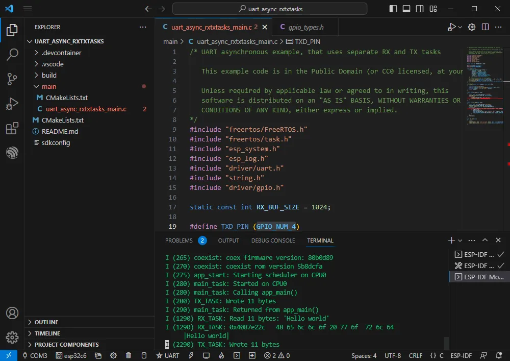
UART
Official example path: peripherals -> uart -> uart_async_rxtxtasks
Example effect: Self-transmission and reception of UART data when GPIO4 and GPIO5 are shorted.
Hardware Connection
| ESP32-C6 | ESP32-C6 (same board) |
|---|---|
| GPIO4 | GPIO5 |
Software Operation
- Create the official example uart_async_rxtxtasks following the tutorial above (Creating an Example).
- The program is compatible with ESP32-C6; no modification needed.
- Set the COM port and target driver correctly (it is recommended to use the USB COM port – check in Device Manager) , then click Build and Flash to run.
-
Make the hardware connection according to the GPIOs used.
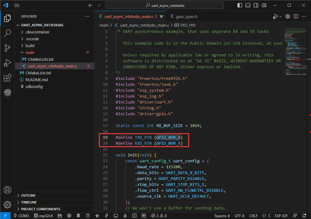
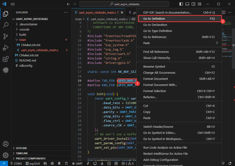
-
You can go to the definition file to see the actual GPIOs used (select GPIO_NUM_4 -> right-click -> Go to Definition).
Bluetooth
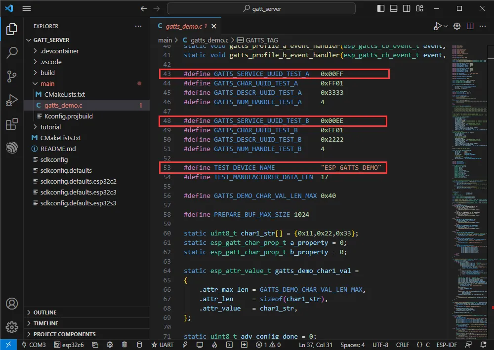
Official example path: bluetooth -> bluedroid -> ble -> gatt_server
Example effect: Data transfer between the ESP32-C6 and a Bluetooth debugging assistant on a mobile phone.
Software Operation
- Install the Bluetooth Debug Assistant on your phone.
- Create the official example gatt_server following the tutorial above (Creating an Example).
- The program is compatible with ESP32-C6; no modification needed.
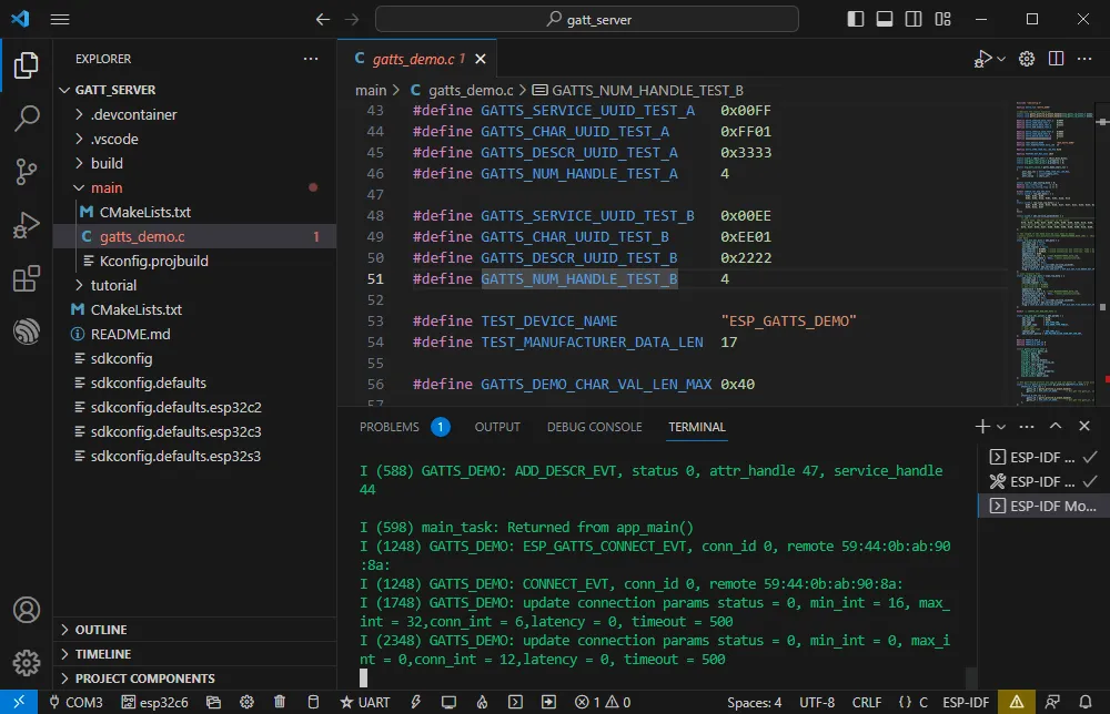
- The Bluetooth name and UUID: the Bluetooth name is ESP_GATTS_DEMO.
-
Set the COM port and target driver correctly (it is recommended to use the USB COM port – check in Device Manager) , then click Build and Flash to run.
-
Connect to the ESP_GATTS_DEMO Bluetooth device on your phone.
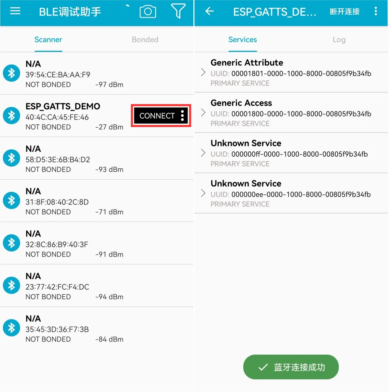
-
Successful connection appears as shown below.
-
According to the UUID values in the program, the two servers below are available; choose one for uplink transmission.
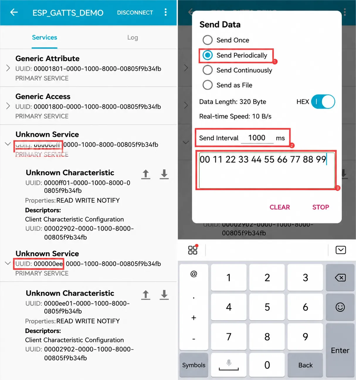
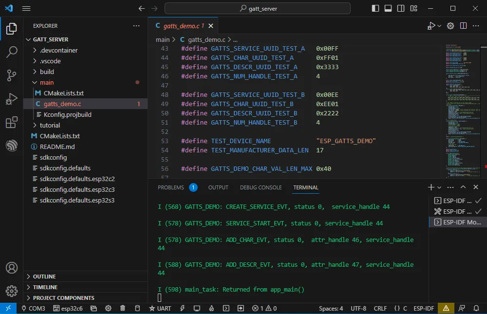
-
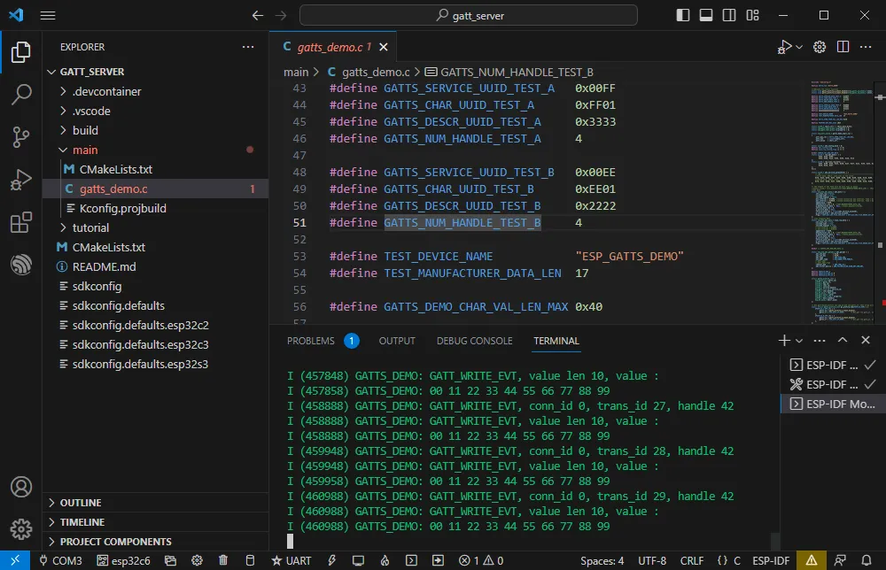
The ESP32-C6 receives the data.
WIFI
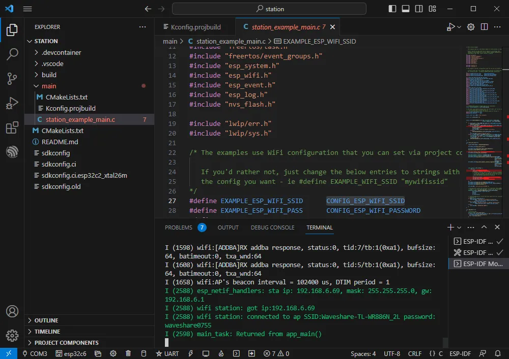
Official example path: wifi -> getting_started -> station Example effect: ESP32-C6 connects to a Wi-Fi network.
Software Operation
- Create the official example station following the tutorial above (Creating an Example).
- Modify the program to connect to the desired Wi-Fi.
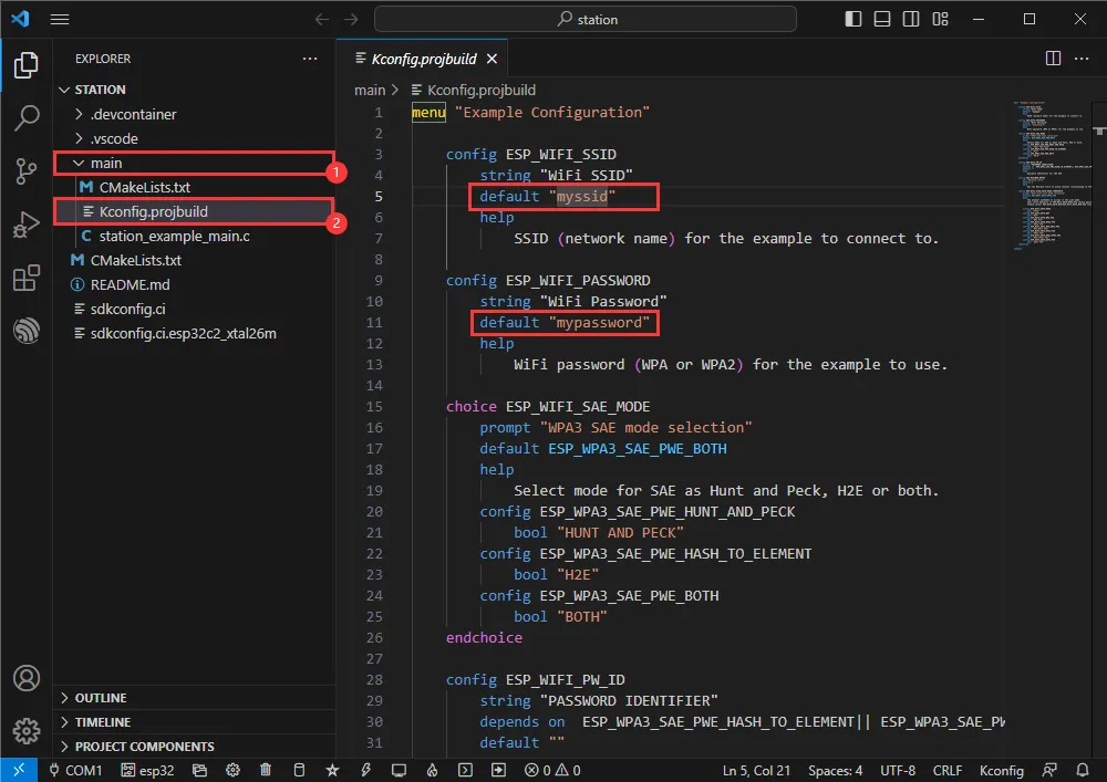
- Open the Kconfig.projbuild file.
-
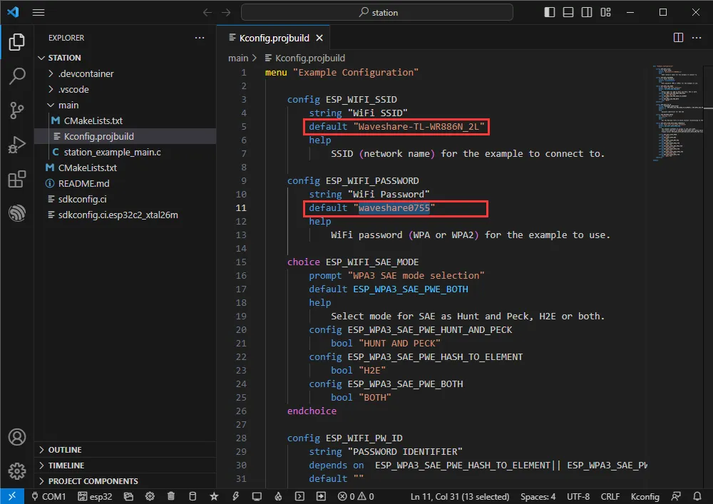
Change the WiFi SSID and WiFi Password to the Wi-Fi credentials you want to connect to.
-
Set the COM port and target driver correctly (it is recommended to use the USB COM port – check in Device Manager) , then click Build and Flash to run.
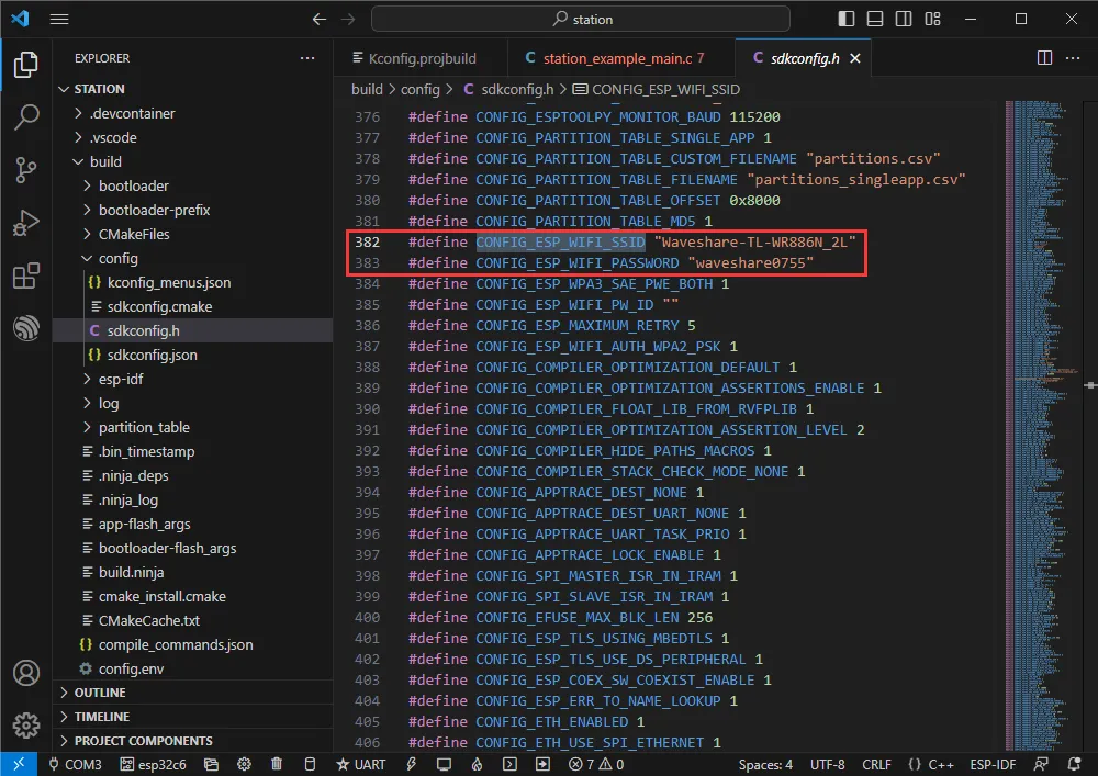
-
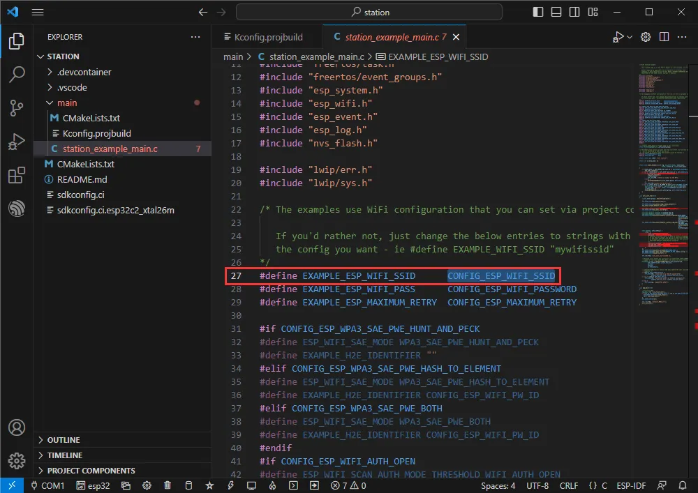
You can check the value of CONFIG_ESP_WIFI_SSID.
-
Open the station example main.c file.
-
Right-click and go to definition.
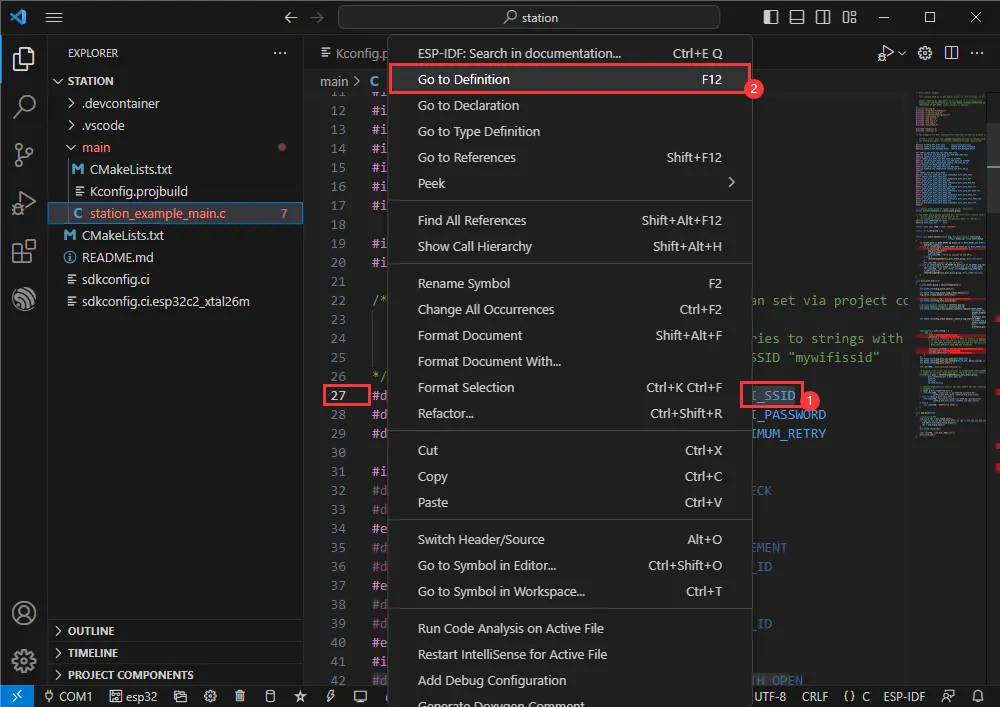
-
You can see the value set earlier.
Zigbee
Official example 1 path: Zigbee -> light_sample -> HA_on_off_switch
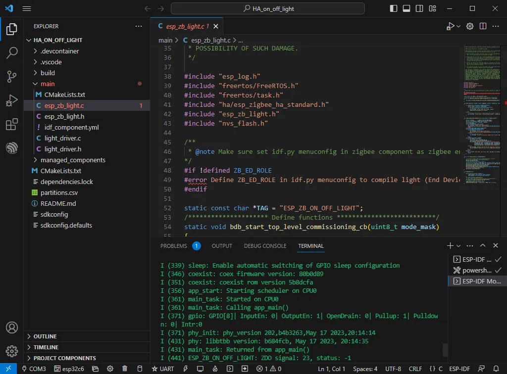
Official example 2 path: Zigbee -> light_sample -> HA_on_off_light
Example effect: Two ESP32-C6 boards; one (flashed with the HA_on_off_switch program) uses its BOOT button to control the RGB LED on the other board.
Note: First flash the HA_on_off_switch program on one board, then flash the HA_on_off_light program on the other board.
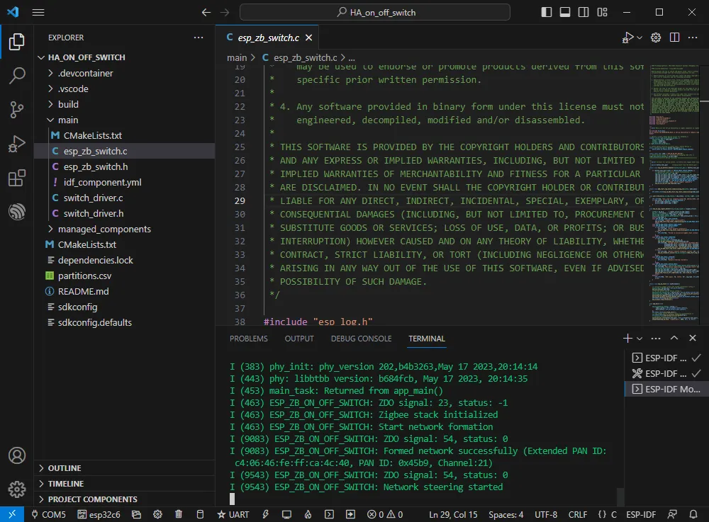
Software Operation 1
- Create the official example HA_on_off_switch following the tutorial above (Creating an Example).
- The program is compatible with ESP32-C6; no modification needed.
- Set the COM port and target driver correctly (it is recommended to use the USB COM port – check in Device Manager) , then click Build and Flash to run.
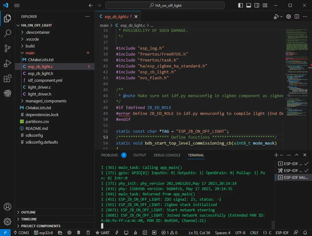
Software Operation 2
-
Create the official example HA_on_off_light following the tutorial above (Creating an Example).
-
The program is compatible with ESP32-C6; no modification needed.
-
Set the COM port and target driver correctly, then click Build and Flash to run. (Wait a moment for the two chips to establish a connection.)
-
If it remains disconnected as shown below, the device may have residual network information from other networks. You can erase the device (see erase tutorial) and then re-establish the network.
JTAG Debugging
Software Operation
-
Create an example to debug – this example uses the official hello_world example (Creating an Example).
-
Modify the launch.json file.
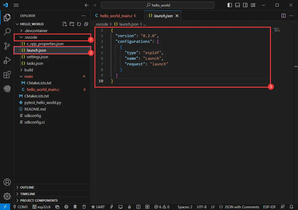
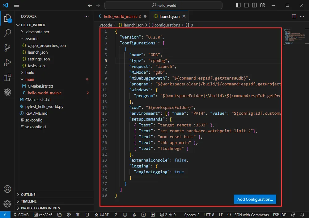
-
Enter the following content:
{"version": "0.2.0","configurations": [{"name": "GDB","type": "cppdbg","request": "launch","MIMode": "gdb","miDebuggerPath": "${command:espIdf.getXtensaGdb}","program": "${workspaceFolder}/build/${command:espIdf.getProjectName}.elf","windows": {"program": "${workspaceFolder}\\build\\${command:espIdf.getProjectName}.elf"},"cwd": "${workspaceFolder}","environment": [{ "name": "PATH", "value": "${config:idf.customExtraPaths}" }],"setupCommands": [{ "text": "target remote :3333" },{ "text": "set remote hardware-watchpoint-limit 2"},{ "text": "mon reset halt" },{ "text": "thb app_main" },{ "text": "flushregs" }],"externalConsole": false,"logging": {"engineLogging": true}}]}
- The program is compatible with ESP32-C6; no modification needed.
- Set the COM port and target driver correctly (use the USB interface – the UART interface does not support JTAG debugging; the corresponding COM port can be checked in Device Manager), then click Build and Flash to run.
-
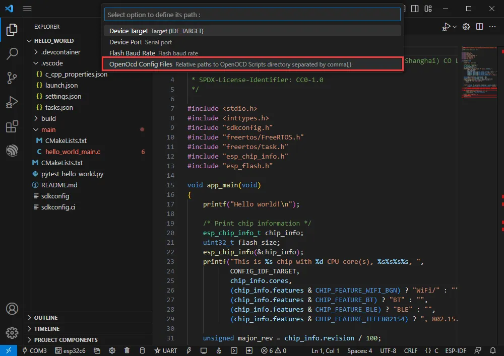
Press the shortcut F1 and enter:
ESP-IDF:Device configuration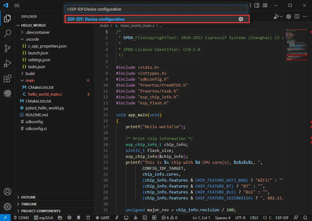
-
Select OpenOcd Config Files
-
Enter board/esp32c6-builtin.cfg (if this is already the default, just press Enter).
board/esp32c6-builtin.cfg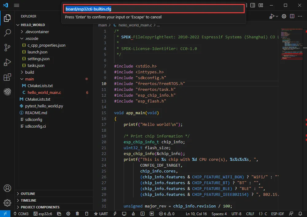
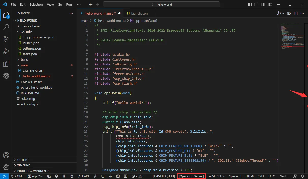
-
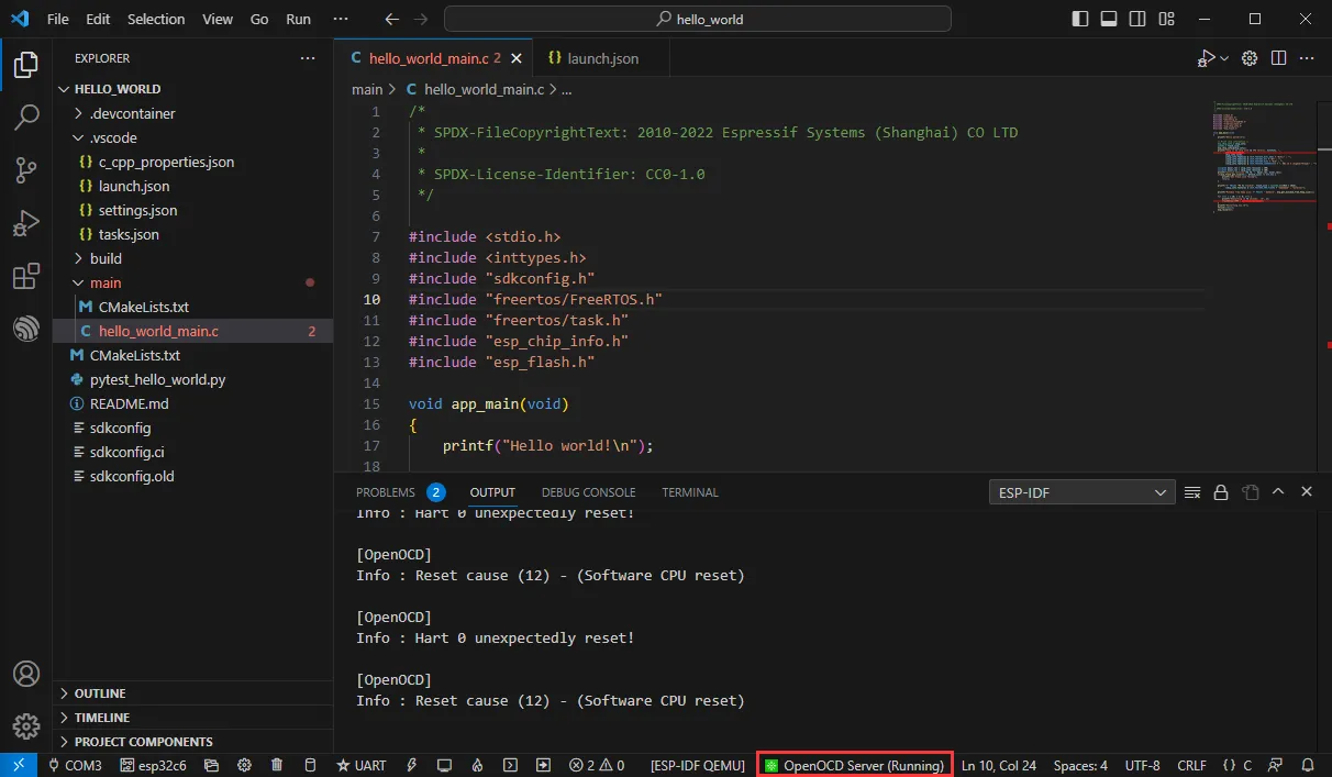
Expand the window width until [OpenOCD Server] appears at the bottom.
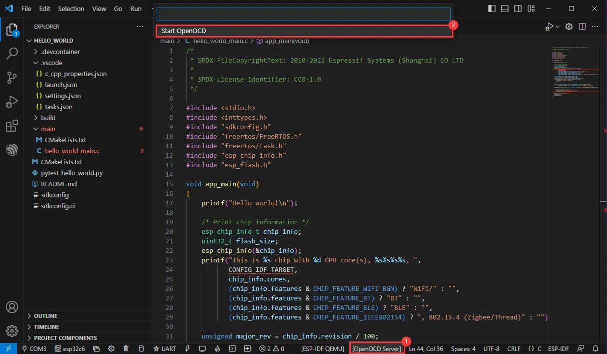
-
Click [OpenOCD Server] and select Start OpenOCD.
-
Successful startup looks like this:
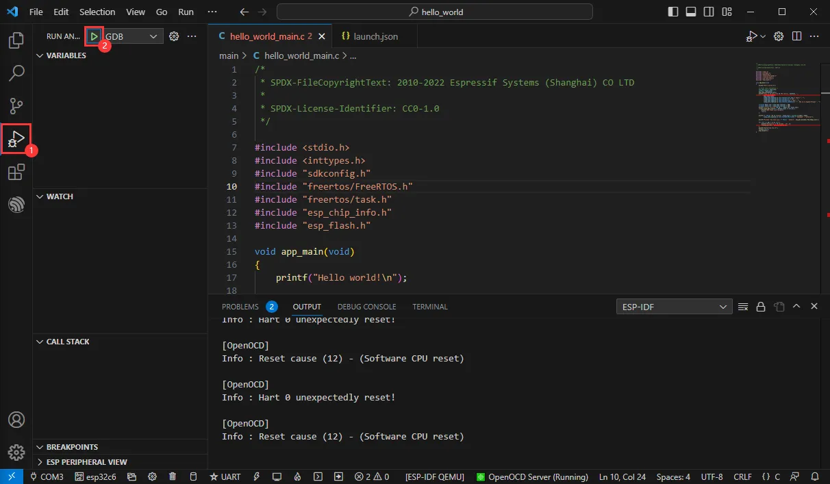
-
Enter debug mode by clicking Debug.
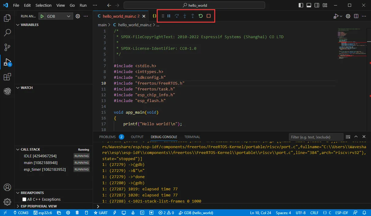
-
Successfully entered the debug interface.
Erasing Device Flash
-
Extract the software resource package Flash debugging software
-
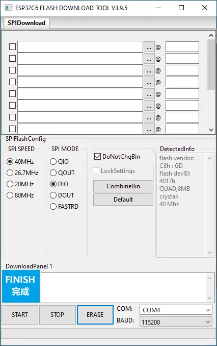
Open the flash_download_tool_3.9.5.exe software, select ESP32-C6 and UART
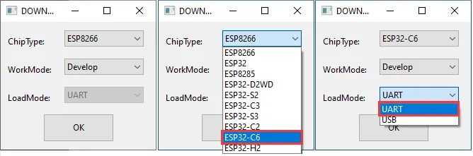
-
Select the UART port number, click START (do not select any bin file)
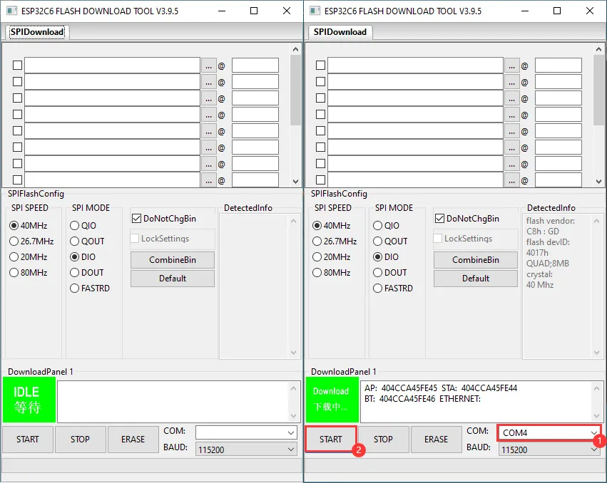
-
Wait for the flashing to complete, then click Erase
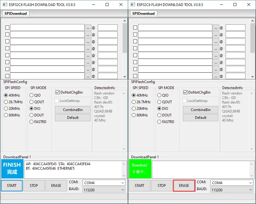
-
Wait for the erasing to complete