Example: ADC Analog Signal Acquisition
The core logic of this tutorial applies to all ESP32 boards, but all the operation steps are explained using the example of the Waveshare ESP32-S3-Zero mini development board. If you are using a development board of another model, please modify the corresponding settings according to the actual situation.
This tutorial will introduce how to use the Espressif ESP-IDF framework to read the analog voltage from a potentiometer via the ADC (Analog-to-Digital Converter) peripheral in oneshot conversion mode, and use the ADC calibration driver to convert raw data into actual voltage in millivolts (mV).
1. ADC Peripheral
ADC (Analog-to-Digital Converter) is used to convert continuously varying analog voltages into discrete digital values.
ESP32-S3 has two built-in 12-bit SAR ADCs:
- ADC1: Corresponds to GPIO1–GPIO10 (10 channels total), recommended for use.
- ADC2: Corresponds to GPIO11–GPIO20, shares hardware resources with Wi-Fi. It cannot be used reliably when Wi-Fi is enabled. Use ADC1 if your application involves Wi-Fi/Bluetooth.
12-bit resolution means the raw result ranges from 0 ~ 4095. The ADC input voltage range is determined by the attenuation setting (data from ESP Hardware Design Guidelines - ADC). For ESP32-S3:
| Attenuation Option | ESP32-S3 Recommended Input Range (approx.) |
|---|---|
ADC_ATTEN_DB_0 | 0 ~ 950 mV |
ADC_ATTEN_DB_2_5 | 0 ~ 1250 mV |
ADC_ATTEN_DB_6 | 0 ~ 1750 mV |
ADC_ATTEN_DB_12 | 0 ~ 2900 mV |
To measure conventional signals in the 0~3.3V range, use ADC_ATTEN_DB_12. Note that attenuation does not "amplify the input" — instead, it attenuates the internal reference voltage of the ADC to extend the measurable range.
This is the upper limit of the ADC's linear region. Beyond this value, readings will "saturate" near the maximum (4095), but the voltage value will no longer be accurate.
1.1 ADC Performance and Calibration Schemes Across ESP32 Chips
The SAR ADCs in ESP32 series chips have different resolution, voltage range, linearity, and calibration schemes due to architecture and process variations. The following table summarizes the key parameters for common models (data source: Comparing ADC Performance of Espressif SoCs):
| Chip | Resolution | Channels | Range (mV) | DNL | INL | Calibration |
|---|---|---|---|---|---|---|
| ESP32 | 12-bit | 8+10 | 150 – 2450 | ±7 | ±12 | Line Fitting |
| ESP32-S2 | 13-bit | 10+10 | 0 – 2500 | ±7 | ±12 | Line Fitting |
| ESP32-S3 | 12-bit | 10+10 | 0 – 2900 | ±4 | ±8 | Curve Fitting |
| ESP32-C2 | 12-bit | 5 | 0 – 2800 | +3, -1 | +8, -4 | Line Fitting |
| ESP32-C3 | 12-bit | 6 | 0 – 2500 | ±7 | ±12 | Curve Fitting |
| ESP32-C5 | 12-bit | 6 | 0 – 3300 | ±5 | ±5 | Curve Fitting |
| ESP32-C6 | 12-bit | 7 | 0 – 3300 | +12,-8 | ±10 | Curve Fitting |
| ESP32-H2 | 12-bit | 5 | 0 – 3300 | +12,-8 | ±10 | Curve Fitting |
| ESP32-P4 | 12-bit | 14 | 0 – 3300 | +3,-1 | +3,-5 | Curve Fitting |
Some notable facts:
- Not all chips cover the full 0~3.3V range. The ESP32 starts at 150 mV, the ESP32-S3 tops out at
2.9V. Only the newer generation (C5/C6/H2/P4) can cover the full 03.3V range. - DNL/INL are ADC linearity metrics — smaller numbers are better. ESP32-P4 and C5 perform best in both; ESP32 and ESP32-S2/S3 are relatively worse and rely more on calibration to correct nonlinearity.
- For accuracy-sensitive applications (e.g., voltmeters, battery gauges), ESP32-C2, C5, C6, H2, and P4 are safer choices; ESP32/S3 are suitable for general scenarios (potentiometer reading, sensor trend monitoring).
Line Fitting vs. Curve Fitting
ESP-IDF encapsulates factory calibration data into two calibration schemes. Developers call the unified adc_cali_raw_to_voltage() API, and the underlying algorithm is transparent to the application:
- Line Fitting: Treats the raw reading-to-voltage relationship as a straight line for correction — calculates offset and gain parameters, then substitutes them into a linear formula. Simple and low-overhead, but cannot eliminate nonlinear errors at the voltage extremes. Applicable chips: ESP32, ESP32-S2, ESP32-C2.
- Curve Fitting: Uses a polynomial (higher-order curve) to model the nonlinear relationship between raw readings and voltage. Each attenuation option has a set of coefficients tuned at the chip factory. Can better correct nonlinear bending in the mid-to-high voltage range. Applicable chips: ESP32-S3, ESP32-C3, ESP32-C5, ESP32-C6, ESP32-H2, ESP32-P4.
Calibration significantly improves accuracy. Taking ESP32-S3 as an example, uncalibrated raw readings show obvious nonlinear deviation in the high voltage range (>2750 mV); after enabling Curve Fitting, the full-scale error is compressed to approximately -30 ~ 0 mV (based on Espressif blog test data).
All official Espressif modules have the eFuse bits required for calibration already burned at the factory. Developers do not need to perform calibration themselves. Simply call the corresponding adc_cali_create_scheme_xxx_fitting() function.
In ESP-IDF code, you'll often see conditional compilation like #if ADC_CALI_SCHEME_CURVE_FITTING_SUPPORTED ... #elif ADC_CALI_SCHEME_LINE_FITTING_SUPPORTED .... This is the officially recommended portable template — the same code automatically selects the correct scheme when compiled for different chips, without modification. This example also uses this approach.
1.2 Oneshot Mode and Continuous Mode
ESP-IDF splits the ADC driver into two sets:
- Oneshot Conversion Mode: The CPU actively initiates a single conversion and reads one value. Suitable for on-demand sampling (e.g., periodically reading a potentiometer). Low overhead and easy to use — this example uses this mode.
- Continuous Conversion Mode (DMA): Hardware continuously writes results to memory at a fixed sample rate; the CPU retrieves data via callbacks. Suitable for high-speed, continuous sampling (audio, vibration analysis). Configuration is more complex and is not covered here. For details, refer to ADC Continuous Mode Driver.
1.3 General Steps (Oneshot Mode + Calibration)
-
Include header files
-
Create an ADC unit handle: Use
adc_oneshot_unit_init_cfg_tto specify ADC1/ADC2, then calladc_oneshot_new_unit(). -
Configure the channel: Use
adc_oneshot_chan_cfg_tto specify bit width and attenuation, then calladc_oneshot_config_channel(). -
Create a calibration scheme (recommended): Depending on chip support, call
adc_cali_create_scheme_curve_fitting()(for ESP32-S3, etc.) oradc_cali_create_scheme_line_fitting()(for ESP32, ESP32-S2, ESP32-C2). See Section 1.1 for a comparison of the two schemes. Espressif modules have the calibration eFuse bits burned at the factory — no additional steps are needed from the developer. -
Read and convert:
adc_oneshot_read()gets the raw value;adc_cali_raw_to_voltage()converts the raw value to mV. -
Release resources (if no longer needed):
adc_cali_delete_scheme_curve_fitting()/adc_cali_delete_scheme_line_fitting()to delete the calibration handle,adc_oneshot_del_unit()to delete the ADC unit handle.
2. Example Project
This example uses a potentiometer as an adjustable voltage source, connected to GPIO7 (ADC1_CH6) of the ESP32-S3-Zero. It periodically reads and prints the ADC raw value and the calibrated voltage.
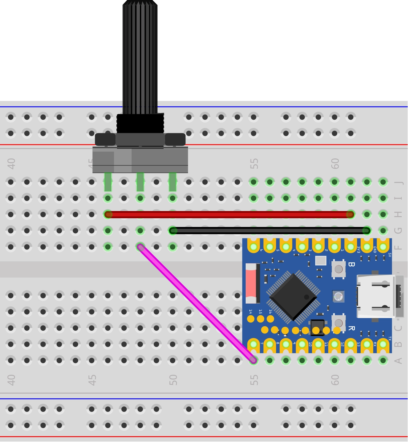
2.1 Circuit
Components required:
- Potentiometer (10 kΩ linear) * 1
- Breadboard * 1
- Wires
- ESP32 development board (Waveshare ESP32-S3-Zero Mini Development Board)
Wiring: Connect the two ends of the potentiometer to 3.3V and GND respectively, and connect the wiper (middle pin) to GPIO7.
ESP32-S3-Zero Pinout Diagram
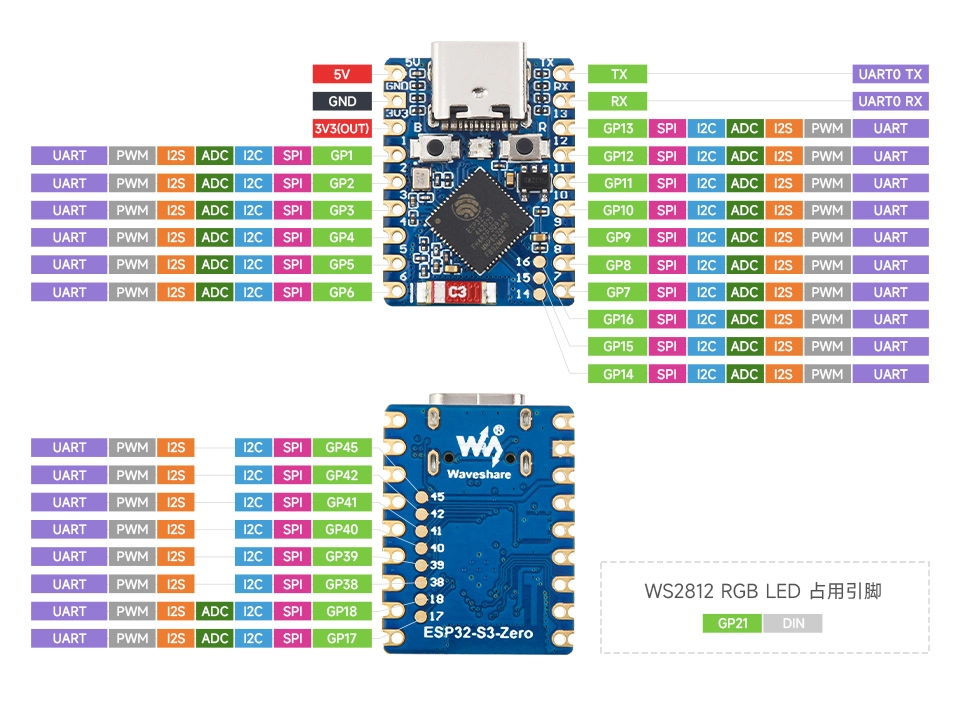
GPIO7 on ESP32-S3 corresponds to ADC1 channel 6 (ADC_CHANNEL_6). For the complete mapping between ADC1 channels and GPIOs, refer to: ESP Hardware Design Guidelines - ADC
2.2 Create Project
-
Create a project. If you are not sure how to do this, refer to Create a Project from Template.
-
Refer to the ADC Oneshot Mode API Reference and ADC Calibration Driver. Follow the guidance in the documentation to complete the following steps.
First, include the header files in main.c:
#include "esp_adc/adc_oneshot.h"#include "esp_adc/adc_cali.h"#include "esp_adc/adc_cali_scheme.h"Then declare the
esp_adccomponent in main/CMakeLists.txt:idf_component_register(SRCS "main.c"INCLUDE_DIRS "."REQUIRES esp_adc)
2.3 Example Code
#include "freertos/FreeRTOS.h"
#include "freertos/task.h"
#include "esp_log.h"
#include "esp_adc/adc_oneshot.h"
#include "esp_adc/adc_cali.h"
#include "esp_adc/adc_cali_scheme.h"
static const char *TAG = "example";
#define ADC_UNIT ADC_UNIT_1 // Use ADC1
#define ADC_CHANNEL ADC_CHANNEL_6 // GPIO7 = ADC1_CH6
#define ADC_ATTEN ADC_ATTEN_DB_12 // 0 ~ ~2900 mV
#define ADC_BITWIDTH ADC_BITWIDTH_DEFAULT // 12-bit
static adc_oneshot_unit_handle_t adc_handle;
static adc_cali_handle_t cali_handle = NULL;
static bool calibrated = false;
static void adc_init(void)
{
// 1. Create ADC unit
adc_oneshot_unit_init_cfg_t unit_cfg = {
.unit_id = ADC_UNIT,
};
ESP_ERROR_CHECK(adc_oneshot_new_unit(&unit_cfg, &adc_handle));
// 2. Configure channel
adc_oneshot_chan_cfg_t chan_cfg = {
.bitwidth = ADC_BITWIDTH,
.atten = ADC_ATTEN,
};
ESP_ERROR_CHECK(adc_oneshot_config_channel(adc_handle, ADC_CHANNEL, &chan_cfg));
// 3. Create calibration scheme
#if ADC_CALI_SCHEME_CURVE_FITTING_SUPPORTED
adc_cali_curve_fitting_config_t cali_cfg = {
.unit_id = ADC_UNIT,
.chan = ADC_CHANNEL,
.atten = ADC_ATTEN,
.bitwidth = ADC_BITWIDTH,
};
if (adc_cali_create_scheme_curve_fitting(&cali_cfg, &cali_handle) == ESP_OK) {
calibrated = true;
ESP_LOGI(TAG, "ADC calibration: Curve Fitting enabled");
}
#elif ADC_CALI_SCHEME_LINE_FITTING_SUPPORTED
adc_cali_line_fitting_config_t cali_cfg = {
.unit_id = ADC_UNIT,
.atten = ADC_ATTEN,
.bitwidth = ADC_BITWIDTH,
};
if (adc_cali_create_scheme_line_fitting(&cali_cfg, &cali_handle) == ESP_OK) {
calibrated = true;
ESP_LOGI(TAG, "ADC calibration: Line Fitting enabled");
}
#endif
if (!calibrated) {
ESP_LOGW(TAG, "ADC calibration not available, raw values only");
}
}
void app_main(void)
{
adc_init();
while (1) {
int raw = 0;
ESP_ERROR_CHECK(adc_oneshot_read(adc_handle, ADC_CHANNEL, &raw));
if (calibrated) {
int voltage_mv = 0;
ESP_ERROR_CHECK(adc_cali_raw_to_voltage(cali_handle, raw, &voltage_mv));
ESP_LOGI(TAG, "raw = %4d, voltage = %4d mV", raw, voltage_mv);
} else {
ESP_LOGI(TAG, "raw = %4d", raw);
}
vTaskDelay(pdMS_TO_TICKS(500));
}
}
2.4 Build and Flash
-
Configure flash options
Before building and flashing, make sure to check and set the correct target device, serial port, and flash method. Refer to Section 2 Run Demo - 1.3 Configure Project.

-
Click
 to automatically build, flash, and monitor in sequence.
 -
After flashing, rotate the potentiometer. The voltage values in the serial monitor will smoothly change from approximately 0 mV to approximately 2900 mV:
I (266) main_task: Calling app_main()I (266) example: ADC calibration: Curve Fitting enabledI (276) example: raw = 0, voltage = 0 mVI (476) example: raw = 294, voltage = 260 mVI (676) example: raw = 1770, voltage = 1490 mVI (876) example: raw = 2315, voltage = 1943 mVI (976) example: raw = 4095, voltage = 3146 mV...
2.5 Code Walkthrough
1. Include Header Files
#include "esp_adc/adc_oneshot.h"
#include "esp_adc/adc_cali.h"
#include "esp_adc/adc_cali_scheme.h"
esp_adc/adc_oneshot.h: ADC oneshot conversion mode driver. Provides core APIs such asadc_oneshot_new_unit(),adc_oneshot_config_channel(), andadc_oneshot_read().esp_adc/adc_cali.h: Common interface for the ADC calibration API, mainly providingadc_cali_raw_to_voltage().esp_adc/adc_cali_scheme.h: Creation/destruction functions for specific calibration schemes (such asadc_cali_create_scheme_curve_fitting()) and macros likeADC_CALI_SCHEME_CURVE_FITTING_SUPPORTED.
All three header files belong to the esp_adc component, so you only need to declare REQUIRES esp_adc once in CMakeLists.txt.
2. Define Global Constants
#define ADC_UNIT      ADC_UNIT_1
#define ADC_CHANNEL   ADC_CHANNEL_6
#define ADC_ATTEN     ADC_ATTEN_DB_12
#define ADC_BITWIDTH  ADC_BITWIDTH_DEFAULT
ADC_UNIT_1: Use ADC1. If Wi-Fi is enabled later, ADC2 will be occupied, so beginner examples uniformly use ADC1.ADC_CHANNEL_6: Corresponds to GPIO7. The ADC channel number is a logical number, not a GPIO number — you need to look up the mapping table. You can also calladc_oneshot_io_to_channel()for runtime conversion.ADC_ATTEN_DB_12: Selects the attenuation, which determines the measurable voltage range. For conventional signals in the 0~3V range, choose 12 dB (ESP32-S3 measured upper limit is ~2.9V, see Section 1.1 for details).ADC_BITWIDTH_DEFAULT: Let the driver use the chip's default bit width. On ESP32-S3, this is 12-bit (ADC_BITWIDTH_12).
3. ADC Initialization (adc_init)
This step accomplishes three things: create the ADC unit, configure the channel, and (attempt to) create a calibration scheme.
-
Create ADC Unit
adc_oneshot_unit_init_cfg_t unit_cfg = { .unit_id = ADC_UNIT };ESP_ERROR_CHECK(adc_oneshot_new_unit(&unit_cfg, &adc_handle));This returns an
adc_oneshot_unit_handle_thandle. All subsequent operations on ADC1 go through this handle. All channels under one ADC unit share this single handle. -
Configure Channel
adc_oneshot_chan_cfg_t chan_cfg = {.bitwidth = ADC_BITWIDTH,.atten = ADC_ATTEN,};ESP_ERROR_CHECK(adc_oneshot_config_channel(adc_handle, ADC_CHANNEL, &chan_cfg));Specifies the bit width and attenuation for the channel. If a project needs to sample multiple channels (e.g., two potentiometers), simply call
adc_oneshot_config_channel()multiple times on the sameadc_handle, configuring each channel separately. -
Create Calibration Scheme
#if ADC_CALI_SCHEME_CURVE_FITTING_SUPPORTEDadc_cali_curve_fitting_config_t cali_cfg = { ... };if (adc_cali_create_scheme_curve_fitting(&cali_cfg, &cali_handle) == ESP_OK) {calibrated = true;}#elif ADC_CALI_SCHEME_LINE_FITTING_SUPPORTEDadc_cali_line_fitting_config_t cali_cfg = { ... };if (adc_cali_create_scheme_line_fitting(&cali_cfg, &cali_handle) == ESP_OK) {calibrated = true;}#endifADC raw readings are just integers from 0~4095. To convert them into accurate millivolt values, the chip's factory-burned calibration parameters are needed. As mentioned in Section 1.1, ESP32-S3 supports Curve Fitting while some older chips support Line Fitting — the code uses
#if / #elifcompile-time macros to select the appropriate branch, so the same code automatically uses the correct scheme on different chips. If neither branch is supported (rare) or the calibration handle creation fails,calibratedremainsfalse, and the program degrades to outputting raw values only without affecting operation.noteNote that the two schemes use different configuration structs: Curve Fitting uses
adc_cali_curve_fitting_config_t(which has an extrachanfield), while Line Fitting usesadc_cali_line_fitting_config_t. However, the release interface and subsequent APIs likeadc_cali_raw_to_voltage()are unified — business code doesn't need to know which scheme is being used.
4. Main Loop: Read and Convert
int raw = 0;
ESP_ERROR_CHECK(adc_oneshot_read(adc_handle, ADC_CHANNEL, &raw));

if (calibrated) {
    int voltage_mv = 0;
    ESP_ERROR_CHECK(adc_cali_raw_to_voltage(cali_handle, raw, &voltage_mv));
    ...
}
adc_oneshot_read(): Initiates a single conversion and writes the result toraw. Do not call this in an ISR — this function uses a mutex internally and can only be used in a normal task context.adc_cali_raw_to_voltage(): Uses the calibration handle to convert the raw value to mV. The returned value is voltage after curve fitting, which is much more accurate than a simple linear conversion (raw * Vmax / 4095).vTaskDelay(pdMS_TO_TICKS(500)): Sample once every 500 ms. The ADC's conversion speed is far higher than this — this is just to control the serial output rate.
adc_oneshot_get_calibrated_result()ESP-IDF provides a convenience function adc_oneshot_get_calibrated_result() that completes both "read raw value + calibration conversion" in one call:
int voltage_mv = 0;
ESP_ERROR_CHECK(adc_oneshot_get_calibrated_result(adc_handle, cali_handle, ADC_CHANNEL, &voltage_mv));
This example intentionally splits it into two steps so you can clearly see that "raw reading" and "calibration conversion" are two independent operations. After understanding this, you can use this convenience function to simplify the code in actual projects.
If you observe significant reading jitter, consider combining the following two methods:
- Hardware filtering (officially recommended): Connect a 100 nF ceramic capacitor between the ADC input pin and GND as a bypass capacitor to effectively filter out high-frequency noise. See ADC Calibration Driver - Minimize Noise.
- Software oversampling: Read N times consecutively in a loop (e.g., 16 times) and average the results to significantly smooth the readings.
For scenarios requiring higher sample rates, consider switching to continuous sampling mode (see ADC Continuous Mode Driver).
3. Reference Links
- ESP-IDF Programming Guide - ESP32-S3 ADC Oneshot Mode Driver
- ESP-IDF Programming Guide - ESP32-S3 ADC Calibration Driver
- ESP-IDF Programming Guide - ADC Continuous Mode Driver
- Comparing ADC Performance of Espressif SoCs (Espressif Developer Blog)
- ESP-IDF Example: peripherals/adc/oneshot_read
- ESP-FAQ - Why can't the ESP32-S3 ADC configured with ADC_ATTEN_DB_12 reach the nominal 3100 mV?
- ESP32 Hardware Design Guidelines - ADC