Example: I2C Master Communication
The core logic of this tutorial applies to all ESP32 boards, but all the operation steps are explained using the example of the Waveshare ESP32-S3-Zero mini development board. If you are using a development board of another model, please modify the corresponding settings according to the actual situation.
This tutorial introduces how to use the ESP-IDF I2C master driver to scan all I2C devices on the bus and print their addresses. It demonstrates I2C bus initialization and the usage of
i2c_master_probe().
1. I2C Peripheral

I2C (Inter-Integrated Circuit) is a two-wire serial communication protocol commonly used for connecting sensors, displays, EEPROMs, and other peripherals. Key features:
- Two-wire communication: Only SDA (data line) and SCL (clock line) are needed, plus a common ground — three wires total.
- Master-slave architecture: Multiple devices can be connected on a single bus, each with a unique 7-bit (or 10-bit) address. The master initiates all communication, and slaves respond based on their address.
- Open-drain + pull-up: All devices can only pull the signal lines low; returning to high level relies on pull-up resistors. This is the physical foundation for multiple I2C devices sharing a bus.
ESP32-S3 has 2 built-in I2C controllers (I2C_NUM_0 and I2C_NUM_1), both supporting master/slave modes. SDA/SCL can be mapped to almost any available GPIO via the GPIO matrix.
1.1 Pull-up Resistors
The SDA and SCL lines of the I2C bus must be connected to pull-up resistors; otherwise, the idle level is undefined and communication cannot proceed. Three common approaches:
| Source | Resistance | Use Case |
|---|---|---|
| Module built-in | Usually 10 kΩ | Most off-the-shelf modules (e.g., Waveshare OLED) already have onboard pull-ups — just connect directly |
| External standalone | 4.7 kΩ recommended | Long bus lines, many devices, high speed (400 kHz+), or custom circuits |
| ESP32 internal | ~45 kΩ (weak) | Emergency use, prototyping; unreliable for long wires or high-speed communication |
The ESP32's internal pull-up resistance is relatively large (tens of kΩ) and is only suitable for short-distance, low-speed scenarios with few devices. For production circuits, use external 4.7 kΩ pull-up resistors or modules with built-in pull-ups.
1.2 Bus + Device Model
The ESP-IDF I2C master driver driver/i2c_master.h uses a two-layer handle model:
- Bus — corresponds to a physical set of SDA/SCL pins.
i2c_master_bus_handle_tdescribes the bus itself (pins, clock source, glitch filtering, etc.). - Device — corresponds to a specific I2C chip on the bus.
i2c_master_dev_handle_tdescribes the device's properties (address, SCL speed, etc.).
A single bus can call add_device multiple times, with each device maintaining its own speed configuration. Subsequent i2c_master_transmit() / i2c_master_receive() calls only need the corresponding device handle — the driver automatically switches to that device's speed for the transfer.
ESP-IDF also retains an older I2C driver driver/i2c.h, which has been marked as End-of-Life in v6.0 and will be removed in v7.0. If you encounter online tutorials with #include "driver/i2c.h", that's the old API — replace it with driver/i2c_master.h as shown in this article.
1.3 General Steps
-
Include header file
#include "driver/i2c_master.h"And declare the dependency in
main/CMakeLists.txt:REQUIRES esp_driver_i2c. -
Create the bus: Fill in an
i2c_master_bus_config_tand calli2c_new_master_bus()to get ani2c_master_bus_handle_t. -
Add a device: Fill in an
i2c_device_config_t(address, SCL speed) and calli2c_master_bus_add_device()to get ani2c_master_dev_handle_t. -
Send/receive data:
- Write:
i2c_master_transmit() - Read:
i2c_master_receive() - Write-then-read (commonly used for reading registers):
i2c_master_transmit_receive() - Probe whether a device responds at a given address:
i2c_master_probe()(only requires the bus handle, no device handle needed)
- Write:
-
(Optional) Release resources:
i2c_master_bus_rm_device(),i2c_del_master_bus().
2. Example Project
This example implements an I2C Scanner: it iterates through the 7-bit I2C address space (0x08 ~ 0x77), probes each address with i2c_master_probe(), and prints the discovered device addresses in a grid format.
When you receive any unfamiliar I2C module, the Scanner is the fastest way to confirm correct wiring, normal device response, and the actual address.
2.1 Circuit
Components required:
- Any I2C module (this example uses the Waveshare 1.5-inch OLED Module, address
0x3D, with onboard pull-up resistors) - Breadboard * 1
- Wires
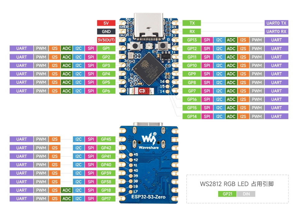
- ESP32 development board (Waveshare ESP32-S3-Zero Mini Development Board)
Wiring table:
| Board Pin | I2C Module | Description |
|---|---|---|
| GPIO 1 | SDA | I2C data line |
| GPIO 2 | SCL | I2C clock line |
| 3.3V | VCC | Power positive |
| GND | GND | Power ground |
ESP32-S3-Zero Pinout Diagram
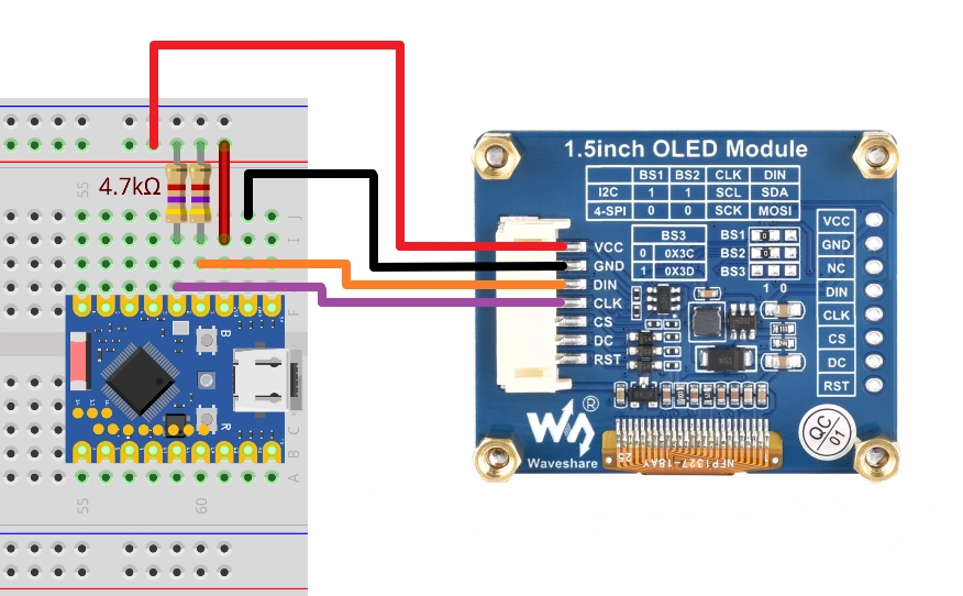
The OLED module used in this example already has onboard pull-up resistors, so no additional connections are needed. If you are connecting a bare chip or custom module without pull-up resistors, add a 4.7 kΩ resistor from each of SDA and SCL to 3.3V. The example code also enables the ESP32's internal weak pull-up as a fallback, ensuring short-distance communication still works without external pull-ups.
2.2 Create Project
-
Create a project. If you are not sure how to do this, refer to Create a Project from Template.
-
Refer to the I2C API Reference. Follow the guidance in the documentation to complete the following steps.
First, include the header file in main.c:
#include "driver/i2c_master.h"Then declare the
esp_driver_i2ccomponent in main/CMakeLists.txt:idf_component_register(SRCS "main.c"INCLUDE_DIRS "."REQUIRES esp_driver_i2c)
2.3 Example Code
#include <stdio.h>
#include "freertos/FreeRTOS.h"
#include "freertos/task.h"
#include "esp_log.h"
#include "esp_err.h"
#include "driver/gpio.h"
#include "driver/i2c_master.h"

static const char *TAG = "example";

#define I2C_PORT             I2C_NUM_0
#define I2C_SDA_PIN          GPIO_NUM_1
#define I2C_SCL_PIN          GPIO_NUM_2
#define I2C_PROBE_TIMEOUT_MS 50

static i2c_master_bus_handle_t bus_handle;

static void i2c_bus_init(void)
{
    i2c_master_bus_config_t bus_cfg = {
        .clk_source                   = I2C_CLK_SRC_DEFAULT,
        .i2c_port                     = I2C_PORT,
        .sda_io_num                   = I2C_SDA_PIN,
        .scl_io_num                   = I2C_SCL_PIN,
        .glitch_ignore_cnt            = 7,
        .flags.enable_internal_pullup = true,
    };
    ESP_ERROR_CHECK(i2c_new_master_bus(&bus_cfg, &bus_handle));
}

static void i2c_scan(void)
{
    int found = 0;
    printf("\nScanning I2C bus...\n");
    printf("     0  1  2  3  4  5  6  7  8  9  a  b  c  d  e  f\n");

    for (uint8_t row = 0; row < 8; row++) {
        printf("%02x: ", row * 16);
        for (uint8_t col = 0; col < 16; col++) {
            uint8_t addr = row * 16 + col;

            // Skip I2C reserved address ranges: 0x00-0x07 and 0x78-0x7F
            if (addr < 0x08 || addr > 0x77) {
                printf("   ");
                continue;
            }

            esp_err_t err = i2c_master_probe(bus_handle, addr, I2C_PROBE_TIMEOUT_MS);
            if (err == ESP_OK) {
                printf("%02x ", addr);
                found++;
            } else {
                printf("-- ");
            }
        }
        printf("\n");
    }

    if (found == 0) {
        ESP_LOGW(TAG, "No I2C devices found. Check wiring and pull-ups.");
    } else {
        ESP_LOGI(TAG, "Scan complete: %d device(s) found.", found);
    }
}

void app_main(void)
{
    i2c_bus_init();

    while (1) {
        i2c_scan();
        vTaskDelay(pdMS_TO_TICKS(5000));
    }
}
2.4 Build and Flash
-
Configure flash options
Before building and flashing, make sure to check and set the correct target device, serial port, and flash method. Refer to Section 2 Run Demo - 1.3 Configure Project.

-
Click
 to automatically build, flash, and monitor in sequence.
 -
After flashing, the serial monitor should output a grid similar to
i2cdetect. The OLED module (address0x3D) will appear in row 4, column 14:Scanning I2C bus...0 1 2 3 4 5 6 7 8 9 a b c d e f00: -- -- -- -- -- -- -- --10: -- -- -- -- -- -- -- -- -- -- -- -- -- -- -- --20: -- -- -- -- -- -- -- -- -- -- -- -- -- -- -- --30: -- -- -- -- -- -- -- -- -- -- -- -- -- 3d -- --40: -- -- -- -- -- -- -- -- -- -- -- -- -- -- -- --50: -- -- -- -- -- -- -- -- -- -- -- -- -- -- -- --60: -- -- -- -- -- -- -- -- -- -- -- -- -- -- -- --70: -- -- -- -- -- -- -- --I (xxxx) example: Scan complete: 1 device(s) found.If the entire table shows
--and the log displaysNo I2C devices found, troubleshoot in this order:- Check if SDA / SCL are swapped;
- Check if the module is powered (VCC, GND);
- Check if the module has pull-up resistors; if not, add external 4.7 kΩ pull-ups to 3.3V, or keep
.flags.enable_internal_pullup = truein the code.
2.5 Code Walkthrough
1. Include Header Files
#include "driver/gpio.h"
#include "driver/i2c_master.h"
driver/i2c_master.h: Entry point for the new ESP-IDF I2C master driver. Containsi2c_master_bus_config_t,i2c_new_master_bus(),i2c_master_probe(), and other APIs. Belongs to theesp_driver_i2ccomponent — addREQUIRES esp_driver_i2cinCMakeLists.txt.driver/gpio.h: Provides theGPIO_NUM_xenumerations for writing SDA / SCL pin numbers.
2. Define Constants
#define I2C_PORT             I2C_NUM_0
#define I2C_SDA_PIN          GPIO_NUM_1
#define I2C_SCL_PIN          GPIO_NUM_2
#define I2C_PROBE_TIMEOUT_MS 50
I2C_NUM_0: Use I2C controller 0. ESP32-S3 has two controllers (0 and 1); this example can use either. You can also pass-1to let the driver automatically select an idle port, which helps avoid port conflicts in multi-component projects. The officiali2c_toolsexample uses this approach.I2C_SDA_PIN/I2C_SCL_PIN: I2C is mapped to any available GPIO via the GPIO matrix. This example uses GPIO1 / GPIO2, consistent with the Arduino tutorial wiring.I2C_PROBE_TIMEOUT_MS: Timeout for each probe. 50 ms is sufficient to cover a single address transmission at 100 kHz (about tens of μs); too short may cause falseESP_ERR_TIMEOUTreports, too long will slow down the entire scan.
3. Bus Initialization (i2c_bus_init)
i2c_master_bus_config_t bus_cfg = {
    .clk_source                   = I2C_CLK_SRC_DEFAULT,
    .i2c_port                     = I2C_PORT,
    .sda_io_num                   = I2C_SDA_PIN,
    .scl_io_num                   = I2C_SCL_PIN,
    .glitch_ignore_cnt            = 7,
    .flags.enable_internal_pullup = true,
};
ESP_ERROR_CHECK(i2c_new_master_bus(&bus_cfg, &bus_handle));
clk_source = I2C_CLK_SRC_DEFAULT: Let the driver select the default clock source (usually the APB clock).i2c_port/sda_io_num/scl_io_num: Specify the controller number and physical pins.glitch_ignore_cnt = 7: Glitch filter count. Pulses narrower than 7 clock cycles are ignored by the hardware, filtering out wiring jitter. 7 is the commonly used value in official examples.flags.enable_internal_pullup = true: Enable the GPIO internal weak pull-up. This is a fallback measure — see Section 1.1 for details.
i2c_new_master_bus() returns bus_handle, which represents the entire bus.
This example only creates a bus and does not call i2c_master_bus_add_device(). This is because i2c_master_probe() is designed for scanning a bus where "you don't yet know which devices exist" — it only needs the bus handle and the address to probe, without requiring a device to be registered first. For normal data transmission/reception (i2c_master_transmit / _receive), you must first add_device to get a device handle.
4. Scan Logic (i2c_scan)
Prints the address grid in 16 columns × 8 rows, with the probe result at each position:
for (uint8_t row = 0; row < 8; row++) {
    printf("%02x: ", row * 16);
    for (uint8_t col = 0; col < 16; col++) {
        uint8_t addr = row * 16 + col;
        if (addr < 0x08 || addr > 0x77) {
            printf("   ");
            continue;
        }
        esp_err_t err = i2c_master_probe(bus_handle, addr, I2C_PROBE_TIMEOUT_MS);
        ...
    }
}
-
Skip reserved addresses: The 7-bit I2C address range is 0x00 ~ 0x7F, where
0x00-0x07and0x78-0x7Fare reserved by the I2C specification for special purposes (broadcast, 10-bit addressing, etc.) and are not assigned to regular devices. These should be skipped during scanning. -
i2c_master_probe(bus_handle, addr, timeout): Sends an address + write command toaddrand determines the return value based on the slave's response:Return Value Meaning ESP_OKACK received — a device exists at this address ESP_ERR_NOT_FOUNDNACK received — no device at this address ESP_ERR_TIMEOUTNo ACK/NACK response on the bus. Official documentation explicitly states this is usually due to missing or improper SDA/SCL pull-ups — check pull-ups first, then wiring. This example only distinguishes between "present (
ESP_OK)" and "absent (other)" cases. If you want to differentiate error types, you can handleESP_ERR_TIMEOUTseparately to indicate pull-up issues.
5. Main Loop
while (1) {
    i2c_scan();
    vTaskDelay(pdMS_TO_TICKS(5000));
}
Scans every 5 seconds. This allows hot-plugging modules during debugging — you'll immediately see devices appearing or disappearing, making it easy to verify wiring.
3. Reference Links
- ESP-IDF Programming Guide - ESP32-S3 I2C API Reference
- ESP-IDF Example: peripherals/i2c/i2c_tools — Official i2c-tools command-line utility with i2cdetect / i2cget / i2cset and more
- ESP-IDF I2C Examples: peripherals/i2c
- I²C-bus specification and user manual (NXP Official Specification)