Example: UART Serial Communication
The core logic of this tutorial applies to all ESP32 boards, but all the operation steps are explained using the example of the Waveshare ESP32-S3-Zero mini development board. If you are using a development board of another model, please modify the corresponding settings according to the actual situation.
This tutorial introduces how to use the Espressif ESP-IDF framework to implement serial data transmission and reception through the UART peripheral. A jumper wire is used to short-circuit the TX and RX pins of the development board, forming a "self-loopback" circuit. This demonstrates the UART driver initialization process, data transmission/reception, and timeout handling for blocking reads.
1. UART Peripheral
UART (Universal Asynchronous Receiver/Transmitter) is one of the most common serial communication interfaces. It is asynchronous, serial, and full-duplex, requiring only TX/RX signal lines plus a common ground to transmit byte streams bidirectionally between two devices.
ESP32-S3 has 3 independent UART controllers built in: UART_NUM_0, UART_NUM_1, UART_NUM_2. Each controller can be independently configured for baud rate, data bits, stop bits, parity, and other parameters. TX/RX pins can be assigned to almost any available GPIO via the GPIO matrix.
1.1 Log Output and UART Controllers
On traditional MCUs, printf is usually redirected to a UART — log output = UART output. However, on ESP32 this is not always the case: the output destination of printf() and ESP_LOGI() is determined by the development board hardware and may be a UART or USB Serial/JTAG.
- Traditional ESP32 / ESP32 boards with USB-TTL bridge chips: Logs default to UART0 (GPIO1 TX / GPIO3 RX), converted to USB output by the onboard CH340/CP2102 bridge chip. In this case, UART0 is already occupied by logging, and the application should use UART1/UART2.
- Waveshare ESP32-S3-Zero and other boards with native USB: Logs default to USB Serial/JTAG — this is the USB-CDC peripheral built into the ESP32-S3 chip, independent of all UART controllers. Therefore, UART0, UART1, and UART2 are all idle and can be freely used by the application.
| Board Type | Log (ESP_LOGI) Output | UART0 Status | Application Should Use |
|---|---|---|---|
| Classic ESP32 + USB-TTL | UART0 (occupied) | Occupied | UART1 / UART2 |
| ESP32-S3-Zero (native USB) | USB Serial/JTAG | Idle | Any of UART0/1/2 |
1.2 General Steps
The ESP-IDF UART driver follows a fixed process of "configure parameters → set pins → install driver → transmit/receive data":
-
Include header file
#include "driver/uart.h"And declare the dependency in
main/CMakeLists.txt:REQUIRES esp_driver_uart. -
Configure communication parameters: Fill in a
uart_config_t(baud rate, data bits, stop bits, parity, flow control, clock source), then calluart_param_config(). -
Set TX/RX pins: Call
uart_set_pin(port, tx, rx, rts, cts). PassUART_PIN_NO_CHANGEfor unused RTS/CTS pins.noteThere is no strict requirement on the order of parameter configuration and pin setup, but both must be completed before
uart_driver_install(). -
Install driver: Call
uart_driver_install(port, rx_buf_size, tx_buf_size, queue_size, &queue, intr_flags)to allocate the TX/RX ring buffers. -
Transmit/Receive data:
- Send:
uart_write_bytes() - Receive:
uart_read_bytes(), with RTOS tick timeout
- Send:
-
(Optional) Uninstall driver:
uart_driver_delete().
2. Example Project
This example uses UART1 for a self-loopback test: the TX and RX pins of the development board are short-circuited with a jumper wire. The program periodically sends a string from TX, then immediately reads it back from RX, and prints both the sent and received content to the USB console (ESP_LOGI).
2.1 Circuit
Components required:
-
Jumper wire
-
ESP32 development board * 1 (Waveshare ESP32-S3-Zero Mini Development Board)
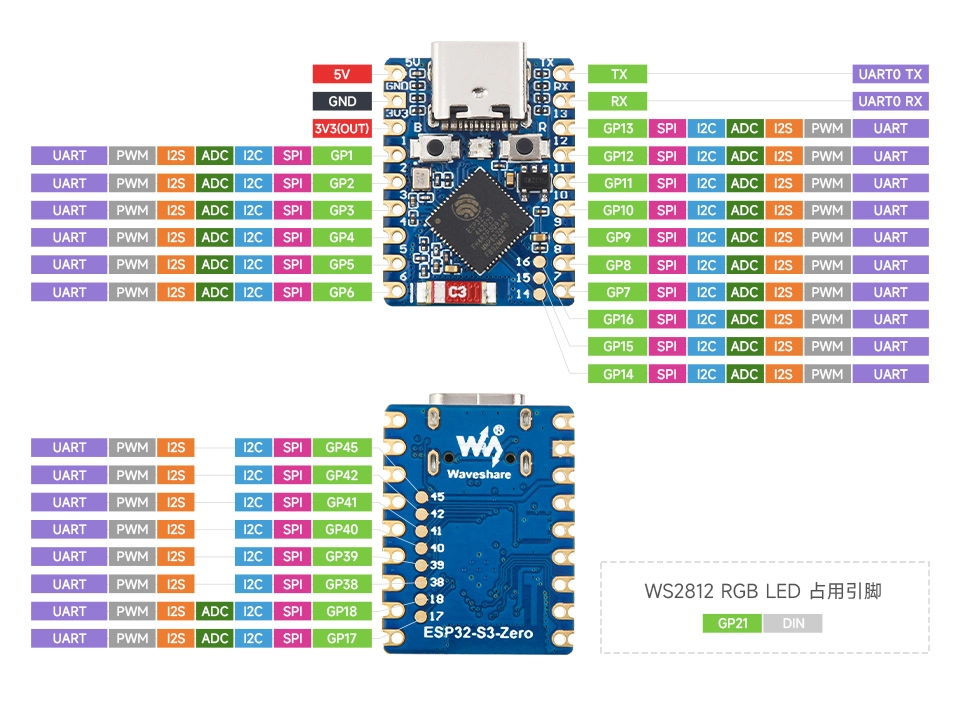
ESP32-S3-Zero Pinout Diagram
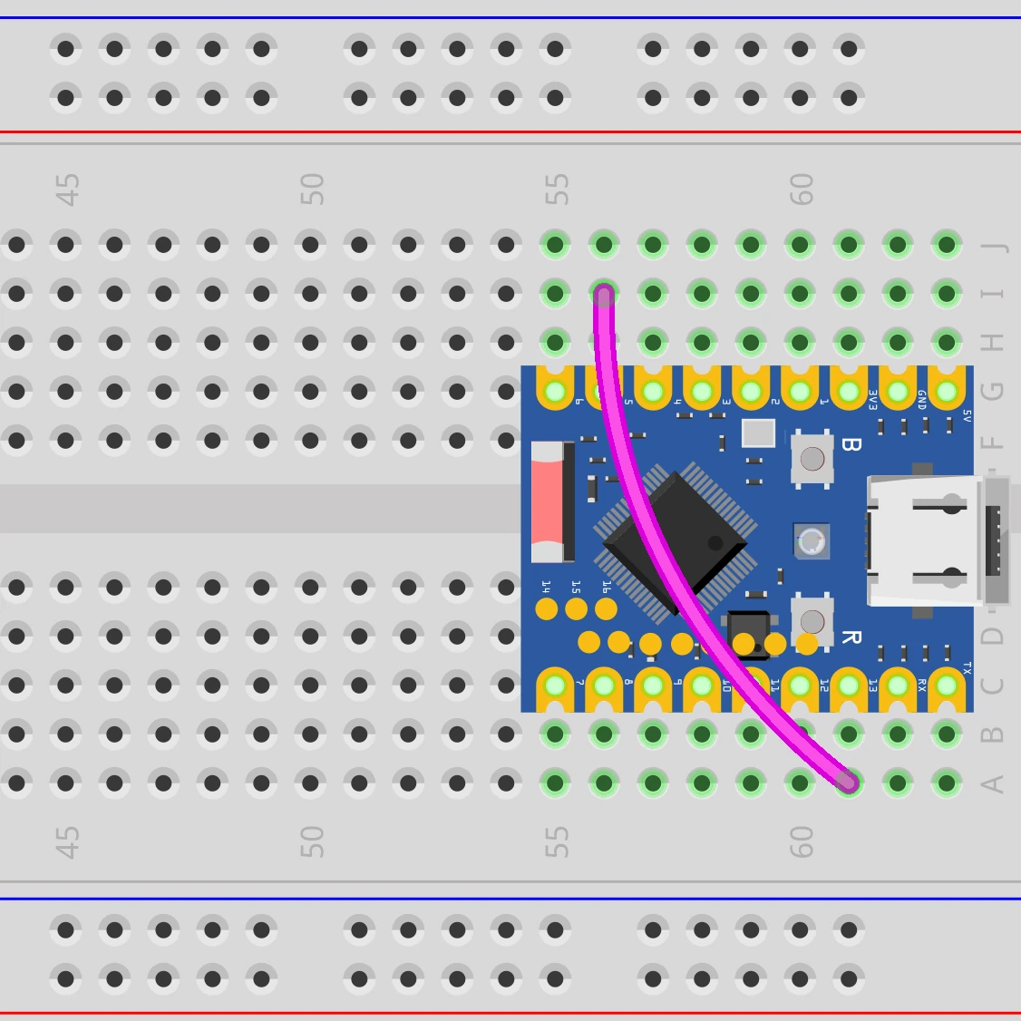
Connect the circuit as shown in the wiring diagram below: use a jumper wire to short GPIO5 (for UART1 TX) and GPIO13 (for UART1 RX).
This example uses only one development board, where TX and RX naturally share the same reference ground, so no additional wiring is needed.
2.2 Create Project
-
Create a project. If you are not sure how to do this, refer to Create a Project from Template.
-
Refer to the UART API Reference. Follow the guidance in the documentation to complete the following steps.
First, include the header file in main.c:
#include "driver/uart.h"Then declare the
esp_driver_uartcomponent in main/CMakeLists.txt:idf_component_register(SRCS "main.c"INCLUDE_DIRS "."REQUIRES esp_driver_uart)
2.3 Example Code
#include <string.h>
#include "freertos/FreeRTOS.h"
#include "freertos/task.h"
#include "esp_log.h"
#include "driver/gpio.h"
#include "driver/uart.h"

static const char *TAG = "example";

#define UART_PORT       UART_NUM_1      // Use UART1
#define UART_TX_PIN     GPIO_NUM_5      // UART1 TX → short to RX for loopback
#define UART_RX_PIN     GPIO_NUM_13     // UART1 RX
#define UART_BAUD_RATE  115200
#define UART_BUF_SIZE   1024            // Ring buffer size for TX/RX

static void uart_init(void)
{
    // 1. Configure communication parameters: 115200 8N1, no flow control
    uart_config_t uart_cfg = {
        .baud_rate  = UART_BAUD_RATE,
        .data_bits  = UART_DATA_8_BITS,
        .parity     = UART_PARITY_DISABLE,
        .stop_bits  = UART_STOP_BITS_1,
        .flow_ctrl  = UART_HW_FLOWCTRL_DISABLE,
        .source_clk = UART_SCLK_DEFAULT,
    };
    ESP_ERROR_CHECK(uart_param_config(UART_PORT, &uart_cfg));

    // 2. Bind TX/RX pins; RTS/CTS not used
    ESP_ERROR_CHECK(uart_set_pin(UART_PORT,
                                 UART_TX_PIN, UART_RX_PIN,
                                 UART_PIN_NO_CHANGE, UART_PIN_NO_CHANGE));

    // 3. Install driver: allocate RX/TX ring buffers, no event queue
    ESP_ERROR_CHECK(uart_driver_install(UART_PORT,
                                        UART_BUF_SIZE, UART_BUF_SIZE,
                                        0, NULL, 0));
}

void app_main(void)
{
    uart_init();

    uint8_t rx_buf[128];
    int counter = 0;

    while (1) {
        // Compose a message: e.g., "Hello UART #3"
        char tx_msg[32];
        int tx_len = snprintf(tx_msg, sizeof(tx_msg), "Hello UART #%d\n", counter++);

        // Send
        uart_write_bytes(UART_PORT, tx_msg, tx_len);
        ESP_LOGI(TAG, "TX (%d bytes): %.*s", tx_len, tx_len - 1, tx_msg);  // -1 to remove trailing '\n'

        // Receive: wait up to 200 ms
        int rx_len = uart_read_bytes(UART_PORT, rx_buf, sizeof(rx_buf) - 1,
                                     pdMS_TO_TICKS(200));
        if (rx_len > 0) {
            rx_buf[rx_len] = '\0';
            ESP_LOGI(TAG, "RX (%d bytes): %s", rx_len, (char *)rx_buf);
        } else {
            ESP_LOGW(TAG, "RX timeout (check the jumper between GPIO%d and GPIO%d)",
                     UART_TX_PIN, UART_RX_PIN);
        }

        vTaskDelay(pdMS_TO_TICKS(1000));
    }
}
2.4 Build and Flash
-
Configure flash options
Before building and flashing, make sure to check and set the correct target device, serial port, and flash method. Refer to Section 2 Run Demo - 1.3 Configure Project.

-
Click
 to automatically build, flash, and monitor in sequence.
 -
After flashing, make sure GPIO5 and GPIO13 are short-circuited with a jumper wire. The serial monitor should show TX and RX appearing in pairs:
I (266) main_task: Calling app_main()I (276) example: TX (15 bytes): Hello UART #0I (286) example: RX (15 bytes): Hello UART #0I (1286) example: TX (15 bytes): Hello UART #1I (1296) example: RX (15 bytes): Hello UART #1...If you only see
TXlines andRX timeoutwarnings, the jumper is not connected properly or the pins are wrong. Check that the actual wiring matches the GPIO numbers shown in the serial monitor output.You can also intentionally disconnect the jumper — the serial monitor will show
RX timeoutwarnings. Reconnect it andRXlines will resume immediately.
2.5 Code Walkthrough
1. Include Header Files
#include "driver/gpio.h"
#include "driver/uart.h"
driver/uart.h: The unified entry point for the ESP-IDF UART driver. Contains all APIs includinguart_config_t,uart_param_config(),uart_set_pin(),uart_driver_install(),uart_write_bytes(), anduart_read_bytes().driver/gpio.h: Provides theGPIO_NUM_xenumerations for writing TX/RX pin numbers in a readable way (e.g.,GPIO_NUM_5).
2. Define Constants
#define UART_PORT       UART_NUM_1
#define UART_TX_PIN     GPIO_NUM_5
#define UART_RX_PIN     GPIO_NUM_13
#define UART_BAUD_RATE  115200
#define UART_BUF_SIZE   1024
UART_NUM_1: Use UART controller 1. See Section 1.1 — avoiding UART0 ensures code portability.UART_TX_PIN/UART_RX_PIN: UART1's TX/RX are mapped to GPIO5 and GPIO13 via the GPIO matrix. Any available GPIO can be used — no fixed pin assignment required.UART_BAUD_RATE: 115200 is the common baud rate for ESP32 consoles and most external modules (GPS, sensors, Bluetooth modules, etc.).UART_BUF_SIZE: Size of the ring buffer allocated for TX/RX, in bytes. 1024 bytes is sufficient for this example; adjust based on throughput in actual projects.
3. UART Initialization (uart_init)
Completed in three steps: "parameters → pins → install":
-
Parameter Configuration (
uart_param_config)uart_config_t uart_cfg = {.baud_rate = UART_BAUD_RATE,.data_bits = UART_DATA_8_BITS,.parity = UART_PARITY_DISABLE,.stop_bits = UART_STOP_BITS_1,.flow_ctrl = UART_HW_FLOWCTRL_DISABLE,.source_clk = UART_SCLK_DEFAULT,};This is the common "115200 8N1, no flow control" configuration: 8 data bits, no parity, 1 stop bit, suitable for the vast majority of use cases.
source_clk = UART_SCLK_DEFAULTlets the driver automatically select a suitable clock source (usually the APB clock). -
Pin Binding (
uart_set_pin)uart_set_pin(UART_PORT, UART_TX_PIN, UART_RX_PIN,UART_PIN_NO_CHANGE, UART_PIN_NO_CHANGE);The four pin parameters are TX / RX / RTS / CTS in order. This example only uses TX and RX; RTS and CTS are passed as
UART_PIN_NO_CHANGE, meaning their current state is left unchanged. -
Driver Installation (
uart_driver_install)uart_driver_install(UART_PORT, UART_BUF_SIZE, UART_BUF_SIZE, 0, NULL, 0);The six parameters are: UART port, RX ring buffer size, TX ring buffer size, event queue depth, event queue handle output pointer, and interrupt allocation flags. This example does not use the event queue, so the queue depth is
0and the handle pointer isNULL.noteA TX buffer size of
0is valid, meaning no TX ring buffer is used anduart_write_bytes()will block until all data is written. Passing a non-zero value (like 1024 in this example) makes the send function return immediately, with the ISR transferring data in the background for higher throughput. This example uses the same non-zero buffer size for both RX and TX.
4. Main Loop: Send and Receive
-
Send
uart_write_bytes(UART_PORT, tx_msg, tx_len);Writes
tx_lenbytes fromtx_msginto UART1's TX ring buffer. Since the TX buffer is enabled, the function returns immediately and the data is asynchronously sent by the driver ISR. -
Receive
int rx_len = uart_read_bytes(UART_PORT, rx_buf, sizeof(rx_buf) - 1,pdMS_TO_TICKS(200));Reads up to
sizeof(rx_buf) - 1bytes (leaving one byte for the'\0'terminator), waiting up to 200 ms. The return value is the number of bytes actually read:> 0: Successfully read the corresponding number of bytes;0: Timeout, no data read;-1: Parameter error.
A 200 ms timeout is more than sufficient for transmitting a few dozen bytes at 115200 baud (which takes about 1 ms), while not causing the main loop to stall for too long. In actual projects, the timeout should be set based on the response delay of the communication counterpart.
noteuart_read_bytes()is a blocking call. During the wait period, the current FreeRTOS task yields the CPU — it does not busy-wait. Even setting the timeout toportMAX_DELAY(wait forever) will not consume CPU. -
Logs go through USB Serial/JTAG, independent of UART1
The
ESP_LOGI(TAG, ...)calls in the code output to the VS Code serial monitor via USB Serial/JTAG, which is a separate path from UART1. If UART1's TX/RX are not properly connected, only the RX timeout branch is triggered;ESP_LOGIoutput is unaffected.