Section 5: ESP32-S3-RLCD-4.2 Configuration Example
This section uses the Waveshare ESP32-S3-RLCD-4.2 as an example to demonstrate how to apply the concepts learned in previous sections —
external_components, I²C / SPI bus declarations, and adding different types of components. Each peripheral is covered in its own section and can be selected as needed.
This section uses the Waveshare ESP32-S3-RLCD-4.2 as the example board. The pins and chip models in the configuration are specific to this board. If you are using a different board, adjust the pins and chip configuration according to its schematic.
1. Prerequisites
- Hardware: One Waveshare ESP32-S3-RLCD-4.2, one USB-C data cable, optionally one 18650 battery.
- Network: A working 2.4 GHz Wi-Fi network, with the HA host and the board on the same subnet.
- Prior steps: Sections 1–4 completed. This section heavily reuses the wizard workflow,
substitutions,external_components,!secret, and other concepts introduced in Sections 3 and 4 — refer to the corresponding sections for unfamiliar fields.
The ESP32-S3-RLCD-4.2 has significantly more onboard peripherals than the ESP32-S3-Zero — a reflective LCD, temperature/humidity sensor, battery monitoring, dual microphones, speaker, and two buttons. This section is organized by peripheral, each focusing on its own component configuration. They are independent and can be combined as needed.
2. Hardware Overview
2.1 Onboard Peripherals
| Peripheral | Model | Bus | Notes |
|---|---|---|---|
| Display | ST7305 reflective monochrome LCD | SPI | 400×300 resolution, 4.2 inches, visible under ambient light |
| Temp/Humidity | SHTC3 | I²C (0x70) | — |
| Audio DAC | ES8311 | I²C + I²S | Drives speaker output |
| Audio ADC | ES7210 | I²C + I²S | Captures dual microphones |
| RTC | PCF85063A | I²C | Not used in current configuration |
| Storage | microSD card slot | SPI | Not used in current configuration |
| Battery | 18650 battery holder + ADC | GPIO4 | 3x voltage divider, requires software correction |
| Buttons | BOOT × 1, KEY × 1 | GPIO | Active low |
| Expansion | 2×8 pin 2.54 mm header | — | Reserved for user expansion |
2.2 GPIO Pin Assignment
| GPIO | Function |
|---|---|
| GPIO0 | BOOT button (active low) |
| GPIO4 | Battery ADC |
| GPIO5 | Display DC |
| GPIO8 | I²S DOUT (speaker) |
| GPIO9 | I²S BCLK |
| GPIO10 | I²S DIN (microphone) |
| GPIO11 | SPI CLK (display) |
| GPIO12 | SPI MOSI (display) |
| GPIO13 | I²C SDA |
| GPIO14 | I²C SCL |
| GPIO16 | I²S MCLK |
| GPIO18 | KEY button (active low) |
| GPIO40 | Display CS |
| GPIO41 | Display RESET |
| GPIO45 | I²S LRCLK |
| GPIO46 | Speaker amplifier enable |
GPIO46 controls the speaker amplifier enable signal — the DAC output will only reach the speaker through the amplifier when this pin is pulled high. In subsequent configurations, a switch.gpio is used to default it to on, so the device can output audio immediately after boot.
2.3 Using Community Configurations
devices.esphome.io already includes ready-made configurations for this board. Search for ESP32-S3-RLCD-4.2 to find the community configuration — copy it and modify the Wi-Fi credentials to use it directly.
The rest of this section breaks down the configuration by peripheral, showing how each type of component is added. Pick the snippets you need and add them to your configuration.
3. Base Configuration
Follow the wizard workflow from Section 3 to create a new device: select ESP32-S3 as the chip, click SKIP when the wizard completes, and enter the YAML editor.
The initial configuration generated by the wizard looks like this (the name, keys, and passwords differ for each device — shown here for illustration):
esphome:
  name: esp32-s3-rlcd-42
  friendly_name: ESP32-S3-RLCD-4.2

esp32:
  board: esp32-s3-devkitc-1
  framework:
    type: esp-idf

logger:

api:
  encryption:
    key: "<auto-generated by wizard>"

ota:
  - platform: esphome
    password: "<auto-generated by wizard>"

wifi:
  ssid: !secret wifi_ssid
  password: !secret wifi_password
  ap:
    ssid: "Esp32-S3-Rlcd-42"
    password: "<auto-generated by wizard>"

captive_portal:
api.encryption.key, ota.password, ap.password are randomly generated credentials bound to this device; esphome.name determines the device's mDNS hostname. Copying someone else's entire YAML to replace yours will lose these values, causing HA pairing failure, OTA failure, or mDNS resolution failure.
All subsequent snippets in this section are "appended after the wizard-generated YAML" — keep the above section intact and append subsequent snippets below it.
After the wizard output, append two more sections — these form the "additional base" needed for all examples in this section:
# 8 MB octal PSRAM: display framebuffer and audio buffers depend on it
psram:
  mode: octal
  speed: 80MHz

# ST7305 driver (community component, not yet in ESPHome mainline)
external_components:
  - source: github://kylehase/ESPHome-ST7305-RLCD
    components: [st7305_rlcd]
Key points:
psram:— The ESP32-S3-RLCD-4.2 has 8 MB octal PSRAM onboard; the display framebuffer and audio buffers both depend on it. The mode must beoctalat 80 MHz speed. Without this section, compilation may succeed, but the device will crash at runtime due to insufficient memory.framework.type: esp-idf— The wizard defaults toesp-idf; keep it as-is. Some components (such asesp-nnmentioned in the FAQ) only support the ESP-IDF framework.external_components:— The ST7305 driver has not yet been merged into ESPHome mainline and is pulled fromkylehase/ESPHome-ST7305-RLCD. The syntax was covered in Section 4.3.4.
All subsequent YAML snippets are also "appended" to this configuration and can be selected as needed — if you only need the display, append the display configuration; if you need temperature/humidity, also append the sensor and button sections; and so on. When the same top-level key (like sensor: or switch:) appears multiple times, merge them following the YAML anchor approach introduced in Section 4.
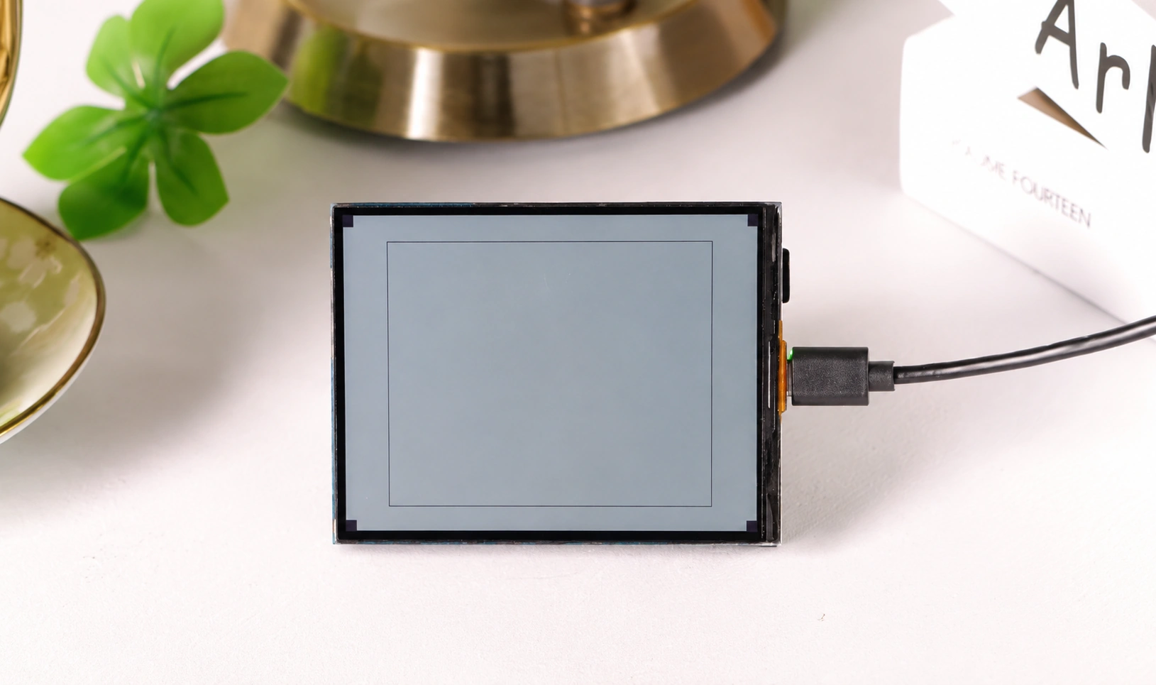
4. Display: ST7305 Reflective LCD
The ST7305 is a monochrome reflective LCD — it has no backlight and forms images by reflecting ambient light. It has a low refresh rate but extremely low power consumption. It communicates with the main controller via SPI, using only the CLK and MOSI data lines (write-only, so MISO is not required).
spi:
  clk_pin: GPIO11
  mosi_pin: GPIO12

display:
  - platform: st7305_rlcd
    model: WAVESHARE_400X300
    id: my_display
    width: 400
    height: 300
    cs_pin: GPIO40
    dc_pin: GPIO5
    reset_pin: GPIO41
    data_rate: 1MHz
    update_interval: 1min
    show_test_card: true
platform: st7305_rlcd— From the external component introduced in Section 3's base configuration.data_rate: 1MHz— The ST7305 is not demanding on timing; 1 MHz is sufficient. Higher frequencies provide no practical improvement for the ST7305 and may introduce communication errors.update_interval: 1min— Reflective displays have no persistence issues, but writing to the screen consumes power and CPU. A 1-minute refresh is adequate for displaying dates, temperature/humidity, etc.show_test_card: true— Displays a test card on first boot to help confirm that wiring is correct.
After flashing, the screen displays a test card, confirming that SPI wiring and the driver are working properly.
4.1 Drawing a Simple Screen
After confirming the display works, remove the show_test_card: true line and draw content via lambda. Displaying text requires declaring fonts first — gfonts:// automatically downloads Google Fonts at compile time:
font:
  - file: "gfonts://Roboto"
    id: font_title
    size: 24
  - file: "gfonts://Roboto"
    id: font_big
    size: 48
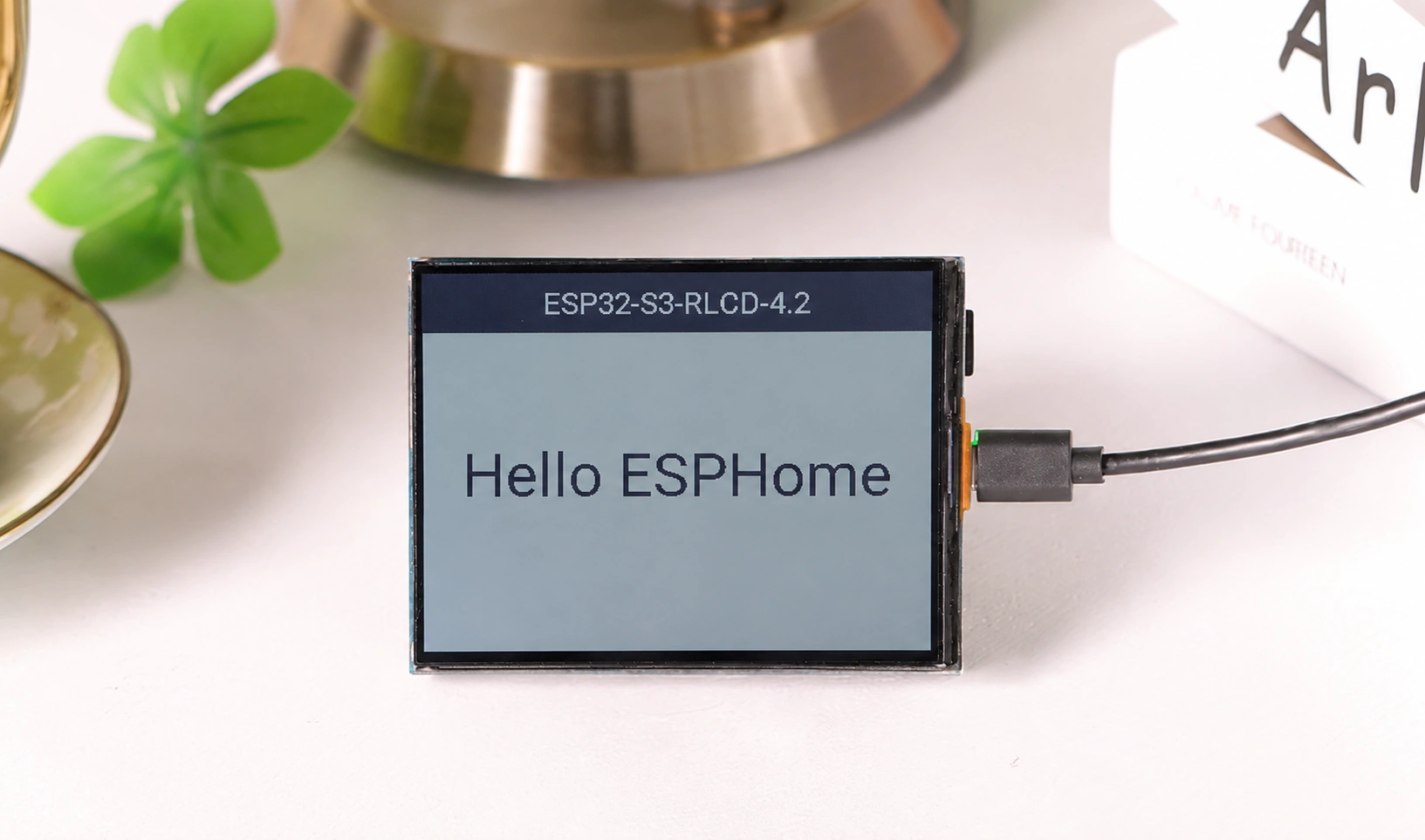
Then replace show_test_card: true in the display: section with a lambda to draw a simple screen with a title bar:
display:
  - platform: st7305_rlcd
    model: WAVESHARE_400X300
    id: my_display
    width: 400
    height: 300
    cs_pin: GPIO40
    dc_pin: GPIO5
    reset_pin: GPIO41
    data_rate: 1MHz
    update_interval: 1min
    lambda: |-
      // Outer border
      it.rectangle(0, 0, 400, 300);
      // Top title bar
      it.filled_rectangle(0, 0, 400, 48);
      it.print(200, 24, id(font_title), COLOR_OFF, TextAlign::CENTER, "ESP32-S3-RLCD-4.2");
      // Centered large text
      it.print(200, 170, id(font_big), TextAlign::CENTER, "Hello ESPHome");
The drawing coordinate system has the top-left corner of the screen as the origin (0, 0), with x increasing to the right and y increasing downward. Some commonly used methods:
it.print(x, y, font, [color,] [align,] "text")— Draws text.TextAlign::CENTERmakes the coordinate the text center point.it.rectangle(x, y, w, h)/it.filled_rectangle(...)— Outline / filled rectangle.it.line(x1, y1, x2, y2)— Line.
A monochrome display has only two colors: COLOR_ON (pixel on) and COLOR_OFF (pixel off). After filling the title bar with a filled rectangle, text needs to specify COLOR_OFF to display as inverted (light on dark background).
Display components do not generate entities in HA — the display is just a "canvas." For the complete drawing API, see Display Rendering Engine.
The above draws static content. After integrating sensors, you can also display real-time temperature/humidity, battery level, etc. — see the "Displaying Sensor Readings" section below for a complete example.
5. Sensors and Buttons
5.1 I²C Bus
The SHTC3, ES8311, and ES7210 share one I²C bus — declare it once:
i2c:
  sda: GPIO13
  scl: GPIO14
  scan: true
  id: bus_a
scan: true scans the bus at boot and prints detected slave addresses in LOGS. On first boot, check the logs — you should see at least 0x18 (ES8311), 0x40 or 0x42 (ES7210), and 0x70 (SHTC3). If any are missing, the corresponding sensors and audio will not work properly.
5.2 SHTC3 Temperature and Humidity
sensor:
  - platform: shtcx
    address: 0x70
    update_interval: 60s
    i2c_id: bus_a
    temperature:
      name: "Temperature"
      id: temp_sensor
    humidity:
      name: "Humidity"
      id: hum_sensor
The shtcx platform covers both SHTC1 and SHTC3. temperature and humidity each have their own name, generating two independent numeric entities in HA; id is used for referencing in the display section's lambda.
5.3 Battery Voltage and Percentage
The battery holder connects to GPIO4 through a 3x voltage divider, so the read voltage needs to be multiplied by 3 to get the actual battery voltage. A copy platform then linearly maps the voltage to a 0–100% battery level:
sensor:
  # …continued from 5.2 SHTC3
  - platform: adc
    id: bat_voltage
    name: "Battery Voltage"
    pin: GPIO4
    attenuation: 12db
    update_interval: 60s
    filters:
      - multiply: 3.0

  - platform: copy
    source_id: bat_voltage
    id: bat_level
    name: "Battery Level"
    unit_of_measurement: "%"
    filters:
      - calibrate_linear:
          - 2.5 -> 0.0
          - 4.2 -> 100.0
      - clamp:
          min_value: 0
          max_value: 100
attenuation: 12db— The ESP32-S3's ADC default range can only measure up to about 0.95 V. Attenuation must be set to raise the upper limit to about 3.1 V, otherwise a fully charged 18650 after voltage division (about 1.4 V) would exceed the range.calibrate_linearmaps 2.5 V → 0% and 4.2 V → 100% linearly, corresponding to the empty-to-full voltage range of an 18650;clamplimits values to 0–100 to prevent out-of-range voltages from being incorrectly converted to negative numbers or values above 100.
5.4 User Buttons
The BOOT (GPIO0) and KEY (GPIO18) buttons are both active low. Configure them following the pattern from Section 4.2.1. To bind trigger actions (such as page navigation or display mode switching), add lambda or other actions under on_press: — the audio section's button binding below is one such example.
binary_sensor:
  - platform: gpio
    name: "Boot Button"
    pin:
      number: GPIO0
      inverted: true
      mode: INPUT

  - platform: gpio
    name: "Key Button"
    pin:
      number: GPIO18
      inverted: true
      mode: INPUT
5.5 Displaying Sensor Readings
With sensors in place, replace the font: and display: sections from the display section with the following complete configuration. The screen will display temperature/humidity and battery level — the layout has three sections: top title bar, middle temperature/humidity, and bottom battery bar.
font:
  - file: "gfonts://Roboto"
    id: font_label
    size: 18
  - file: "gfonts://Roboto@700"
    id: font_value
    size: 48
  - file: "gfonts://Roboto"
    id: font_title
    size: 22

display:
  - platform: st7305_rlcd
    model: WAVESHARE_400X300
    id: my_display
    width: 400
    height: 300
    cs_pin: GPIO40
    dc_pin: GPIO5
    reset_pin: GPIO41
    data_rate: 1MHz
    update_interval: 30s
    lambda: |-
      // Top title bar (inverted)
      it.filled_rectangle(0, 0, 400, 40);
      it.print(200, 20, id(font_title), COLOR_OFF, TextAlign::CENTER, "ESP32-S3-RLCD-4.2");

      // Temperature (left half)
      it.print(20, 52, id(font_label), "TEMP");
      it.printf(20, 72, id(font_value), "%.1f", id(temp_sensor).state);
      it.print(160, 92, id(font_label), "C");

      // Humidity (right half)
      it.print(210, 52, id(font_label), "HUMIDITY");
      it.printf(210, 72, id(font_value), "%.0f", id(hum_sensor).state);
      it.print(330, 92, id(font_label), "%");

      // Separator line
      it.line(0, 150, 400, 150);

      // Battery voltage and level
      it.print(20, 162, id(font_label), "BATTERY");
      it.printf(380, 162, id(font_label), TextAlign::TOP_RIGHT,
                "%.2f V  (%.0f%%)", id(bat_voltage).state, id(bat_level).state);

      // Battery progress bar: draw border, then fill based on percentage
      int bx = 20, by = 192, bw = 360, bh = 30;
      it.rectangle(bx, by, bw, bh);
      int fill = (int)((bw - 4) * id(bat_level).state / 100.0);
      if (fill > 0) it.filled_rectangle(bx + 2, by + 2, fill, bh - 4);
Key points:
it.printfis similar toit.printbut supports C format specifiers like%.1fand%.0f, with values passed sequentially afterward.- Values are read via
id(temp_sensor).state,id(bat_level).state, etc., corresponding to the sensors declared in Sections 5.2 and 5.3. - The progress bar is drawn in two steps:
it.rectangledraws the border, then the fill width is calculated based on battery percentage, andit.filled_rectanglefills it in.
To avoid declaring additional glyphs, units are written using ASCII characters (C, %). To display the degree symbol °C, you need to explicitly add ° to the corresponding font's glyphs, otherwise it won't render on screen.
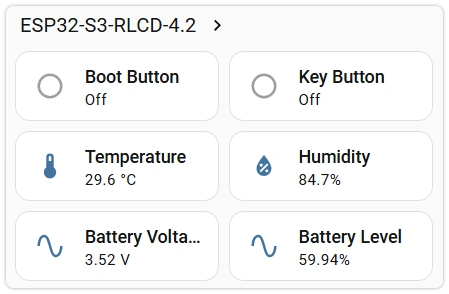
With that, the display, sensors, and buttons are all in place. After flashing, HA will show Temperature, Humidity, Battery Voltage, Battery Level, Boot Button, and Key Button entities, while the screen displays the temperature/humidity and battery level dashboard.

6. Audio: Speaker and Microphone
The onboard speaker (ES8311 DAC) and microphone (ES7210 ADC) share one I²S bus. Below are verification methods for the speaker and microphone separately — you can confirm the hardware is working before building a full voice assistant.
6.1 Speaker: Button-Triggered Ringtone
Use the rtttl component to play a melody (ringtone) through the speaker. rtttl uses the Nokia-era RTTTL ringtone format — the melody is synthesized directly on the device, no audio files need to be downloaded, and the sound is more noticeable than a short beep:
i2s_audio:
  - id: i2s_shared
    i2s_lrclk_pin: GPIO45
    i2s_bclk_pin: GPIO9
    i2s_mclk_pin: GPIO16

audio_dac:
  - platform: es8311
    id: es8311_dac
    bits_per_sample: 16bit
    sample_rate: 16000

speaker:
  - platform: i2s_audio
    id: spk
    i2s_audio_id: i2s_shared
    i2s_dout_pin: GPIO8
    dac_type: external
    audio_dac: es8311_dac
    sample_rate: 16000
    bits_per_sample: 16bit

# Amplifier enable: must be on for output
switch:
  - platform: gpio
    name: "Speaker Enable"
    pin: GPIO46
    restore_mode: RESTORE_DEFAULT_ON

# RTTTL ringtone: synthesized and played directly through the speaker
rtttl:
  speaker: spk
  gain: 80%

button:
  - platform: template
    name: "Play Tune"
    on_press:
      - rtttl.play: "NokiaTune:d=4,o=5,b=225:8e6,8d6,4f#,4g#,8c#6,8b,4d,4e,8b,8a,4c#,4e,2a"
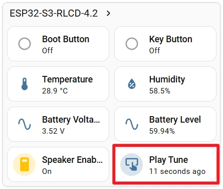
After flashing, a Play Tune button appears in HA. Clicking it plays the ringtone, confirming the speaker and amplifier are working. Speaker Enable (GPIO46) controls the amplifier enable — there is no output when disabled. If the volume is too low, increase rtttl.gain.
rtttl.play takes an RTTTL string — change it to play different ringtones, for example:
# Simple ascending scale
- rtttl.play: "scale:d=4,o=5,b=160:c,d,e,f,g,a,b,c6"
# Alarm siren
- rtttl.play: "siren:d=8,o=5,b=100:d,e,d,e,d,e,d,e"
6.2 Speaker: Text-to-Speech
rtttl has already confirmed the speaker works. If you want the device to speak arbitrary text (e.g., announce notifications or temperature/humidity), you can integrate HA's TTS. This relies on the network and HA's TTS service, making it a more advanced use case.
Unlike Section 6.1, speech playback goes through the media player channel, requiring the speaker to be wrapped as a media_player with a mixer to support both "media" and "announcement" audio streams simultaneously (i2s_audio, audio_dac overlap with above — keep only one copy when merging into a single configuration):
speaker:
  - platform: i2s_audio
    id: spk
    i2s_audio_id: i2s_shared
    i2s_dout_pin: GPIO8
    dac_type: external
    audio_dac: es8311_dac
    sample_rate: 16000
    bits_per_sample: 16bit
  - platform: mixer            # Combine: media + announcements
    id: spk_mixer
    output_speaker: spk
    source_speakers:
      - id: media_in           # Two inputs created by the mixer
      - id: announce_in        # (ids must differ from the resamplers below)
  - platform: resampler        # Pipeline → resampler → mixer input
    id: media_src
    output_speaker: media_in
  - platform: resampler
    id: announce_src
    output_speaker: announce_in

switch:
  - platform: gpio
    name: "Speaker Enable"
    pin: GPIO46
    restore_mode: RESTORE_DEFAULT_ON

media_player:
  - platform: speaker
    id: spk_player
    name: "RLCD Speaker"
    media_pipeline:            # Media browser, TTS speech goes through this
      speaker: media_src
      format: FLAC
      sample_rate: 16000
      num_channels: 1
    announcement_pipeline:     # Plays with announce flag go through this
      speaker: announce_src
      format: FLAC
      sample_rate: 16000
      num_channels: 1
The audio chain is: pipeline → resampler (media_src / announce_src) → mixer input (media_in / announce_in) → mixer → physical speaker spk. Note that mixer input ids and resampler ids must all be different — duplicate ids will cause validation failure.
After flashing, a media player named RLCD Speaker appears in HA. Enter text in HA's TTS dialog and click "Speak" — the device will read it aloud.
TTS audio is generated by HA at runtime and delivered to the device via an HTTP URL (http://<HA>:8123/api/tts_proxy/…). If LOGS show ESP_ERR_HTTP_CONNECT or esp-tls select() timeout, the device cannot access that URL (local rtttl and files: still work because they are packaged into firmware at compile time and don't go through the network).
In HA Settings → System → Network → Local Network, set the internal URL to a form the device can directly access: use the LAN IP (avoid .local), use http:// (not https:// — self-signed certificates will cause TLS handshake timeouts), port 8123, and ensure it's on the same subnet as the device, e.g., http://192.168.1.10:8123.
6.3 Microphone: Wake Word Log
There is no way to directly listen to the microphone output. Instead, you can verify it using on-device wake word detection — this runs entirely on the ESP32 and does not require HA's voice services. When a wake word is detected, it prints a log entry:
audio_adc:
  - platform: es7210
    id: es7210_adc
    bits_per_sample: 16bit
    sample_rate: 16000
    mic_gain: 24dB

microphone:
  - platform: i2s_audio
    id: mic
    i2s_audio_id: i2s_shared      # Reuse the same I²S bus declared in 6.1
    i2s_din_pin: GPIO10
    adc_type: external
    sample_rate: 16000
    bits_per_sample: 16bit
    pdm: false

# Counter: increments each time a wake word is detected
globals:
  - id: wake_count
    type: int
    restore_value: false
    initial_value: "0"

micro_wake_word:
  microphone:
    microphone: mic
    channels: 0
    gain_factor: 4
  models:
    - model: hey_jarvis
  on_wake_word_detected:
    - lambda: 'id(wake_count) += 1;'
    - component.update: my_display      # Refresh display immediately
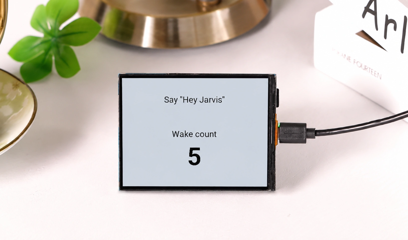
Display the detection results on screen — no need to check logs to confirm. Below is a standalone display configuration that increments a counter with each wake word detection:
font:
  - file: "gfonts://Roboto"
    id: font_title
    size: 22
  - file: "gfonts://Roboto@700"
    id: font_value
    size: 64

display:
  - platform: st7305_rlcd
    model: WAVESHARE_400X300
    id: my_display
    width: 400
    height: 300
    cs_pin: GPIO40
    dc_pin: GPIO5
    reset_pin: GPIO41
    data_rate: 1MHz
    update_interval: 60s
    lambda: |-
      it.print(200, 40, id(font_title), TextAlign::TOP_CENTER, "Say \"Hey Jarvis\"");
      it.print(200, 130, id(font_title), TextAlign::TOP_CENTER, "Wake count");
      it.printf(200, 165, id(font_value), TextAlign::TOP_CENTER, "%d", id(wake_count));
There can only be one display: in the entire configuration. The display configuration here and the one in "Displaying Sensor Readings" are two separate examples — use whichever one suits your current testing purpose.
micro_wake_word requires adding espressif/esp-nn==1.1.2 to esp32.framework.components. The wake word model is also automatically downloaded during compilation. After flashing, say "Hey Jarvis" near the microphone — the counter on screen will increment, confirming the microphone and I²S capture chain are working.
7. Common Issues in This Section
- Clicking Play Tune produces no sound: Confirm
Speaker Enableis on (GPIO46 controls the amplifier enable). For TTS speech with no sound, it's most likely an HA internal URL configuration issue — see the tip in the speech section. - Wake word not responding: Confirm
framework.componentsincludesesp-nnand the model was downloaded. Try increasinggain_factorand make sure you are speaking toward the microphone. - Battery voltage always 0 or out of range: Check if
attenuationis12db, ifmultiply: 3.0is correct, and confirm the actual battery voltage is in the 2.5–4.2 V range.