Section 3: Your First ESPHome Device
The core logic of this tutorial applies to all ESP32 development boards, but all steps are demonstrated using the Waveshare ESP32-S3-Zero Mini Development Board. If you are using a different board, adjust the chip type, board variant, and pin configuration accordingly.
This section uses the Waveshare ESP32-S3-Zero as an example to generate a minimal configuration using the ESPHome wizard, add the onboard RGB LED component, flash via USB for the first time, and control the LED from Home Assistant. It also demonstrates how to update firmware via OTA afterwards.
1. Prerequisites
- Hardware: One Waveshare ESP32-S3-Zero, one USB-C data cable.
- Network: A working 2.4 GHz Wi-Fi network (ESP32-S3 does not support 5 GHz). The HA host and ESP32-S3-Zero must be on the same subnet.
- Prior steps: Sections 1 and 2 completed — HA and the ESPHome app are accessible.
- Browser: The ESPHome Web flashing tool requires Chrome or Edge (Firefox and Safari do not support Web Serial API); the VM passthrough method has no such restriction.
The only controllable onboard component on the ESP32-S3-Zero is a single WS2812 RGB LED on GPIO21. This section uses this LED as the example to walk through the entire process from a blank configuration to controlling the onboard LED via the HA color picker.
2. Create a Configuration with the Wizard
The ESPHome app provides a new device wizard that automatically generates a minimal YAML ready for flashing.
-
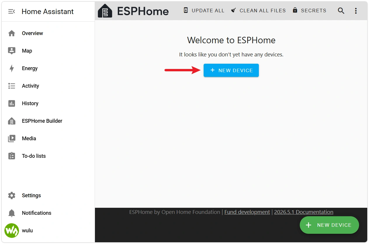
Open the ESPHome app Web interface and click NEW DEVICE in the bottom-right corner.
-
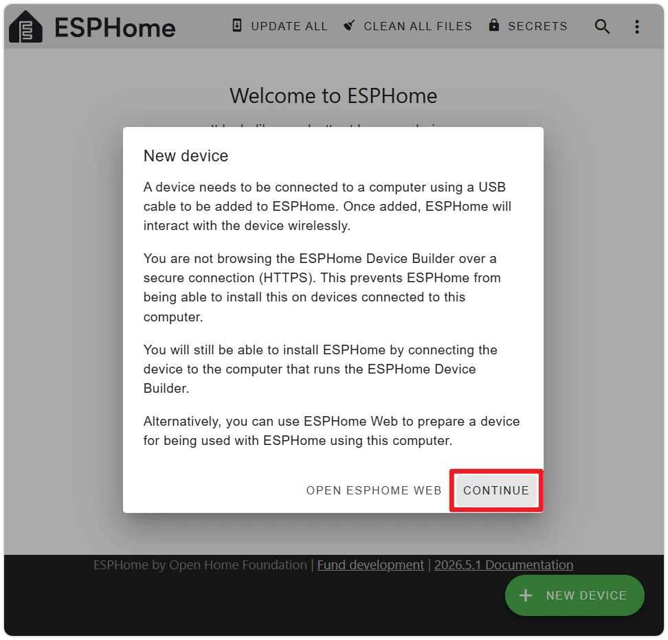
Click CONTINUE in the welcome popup.
-
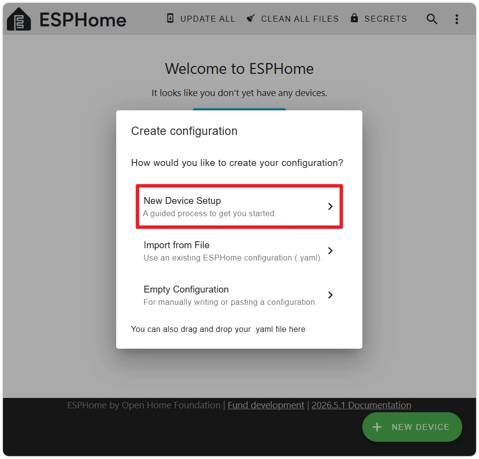
Select New Device Setup.
-
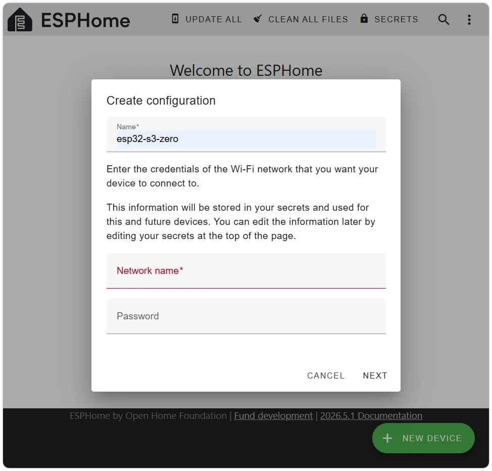
Name the device, then enter your Wi-Fi SSID and password. This tutorial uses
esp32-s3-zeroas the device name — device names can only contain letters, numbers, and hyphens, and also serve as the device's mDNS hostname (<name>.local).note- Wi-Fi only supports 2.4 GHz — ESP32-S3 does not support 5 GHz.
- The SSID and password are automatically written to the ESPHome app's
secrets.yaml, shared by this and future devices — they are not hardcoded into the device YAML (see Section 3.2 for how to modify them).
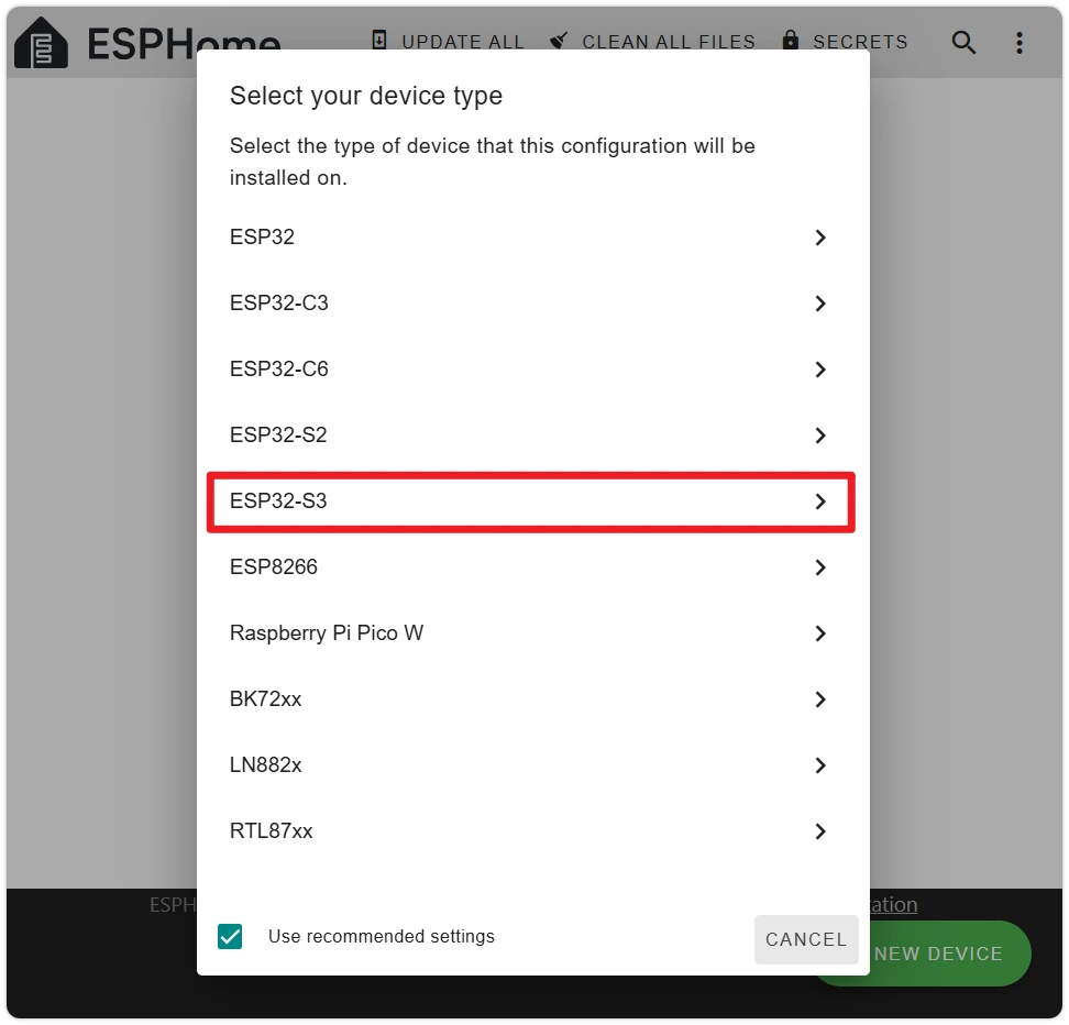
-
Select the device chip type. The ESP32-S3-Zero uses the ESP32-S3 chip — select ESP32-S3.
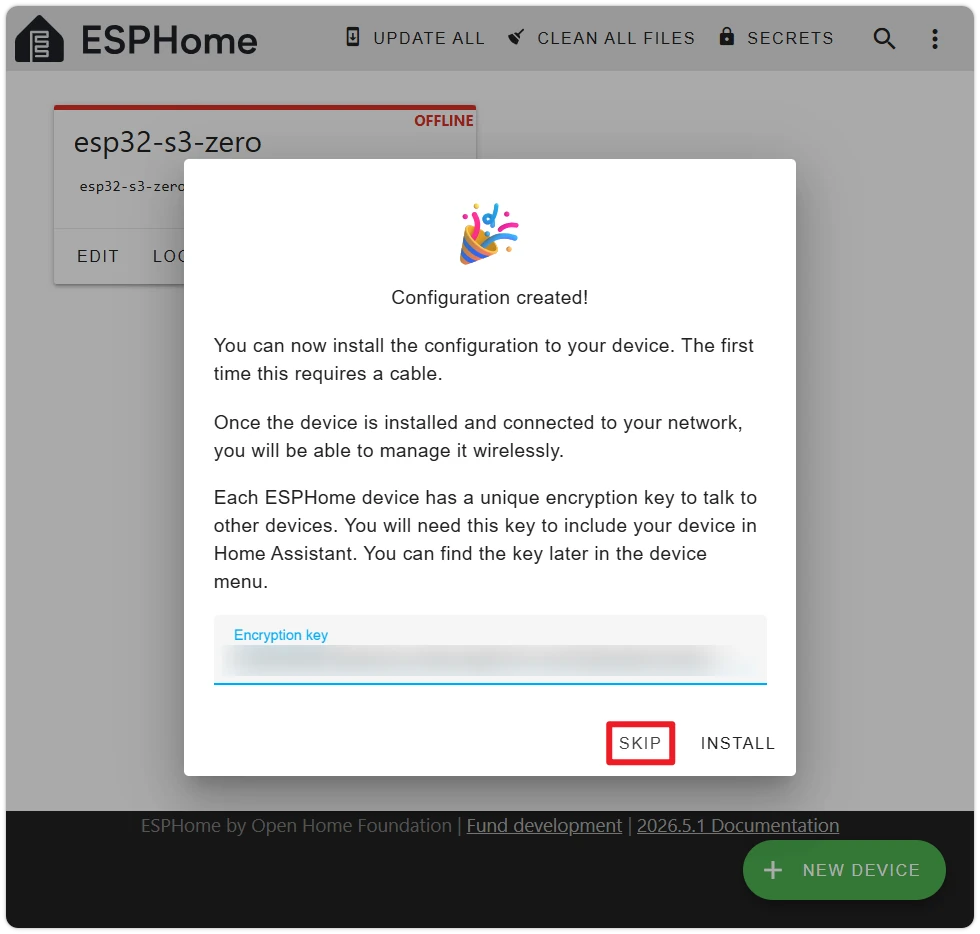
-
After the wizard completes, an INSTALL option will pop up. Click SKIP — we need to add the onboard LED configuration before flashing.
-
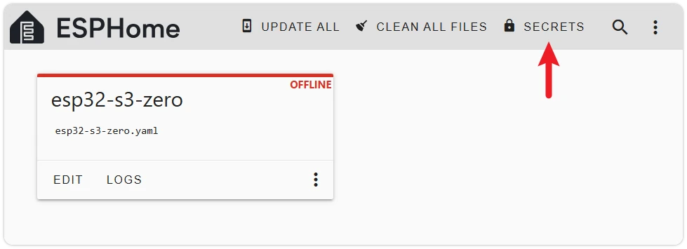
Back on the device list, you will see a device card named
esp32-s3-zero. Click EDIT on the card to open the YAML editor and view the initial configuration generated by the wizard: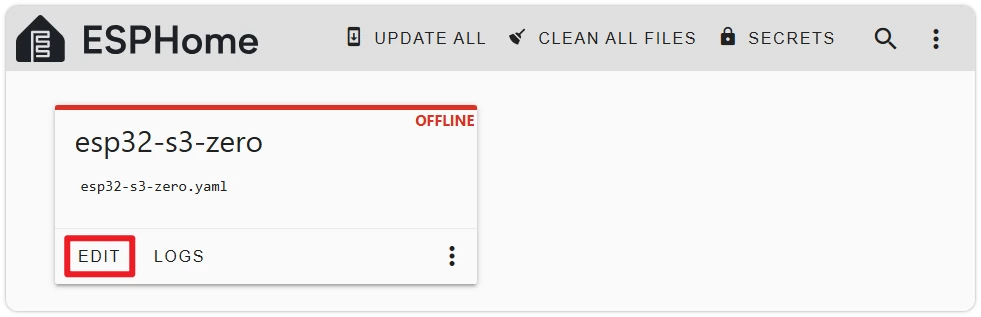 esphome:name: esp32-s3-zerofriendly_name: esp32-s3-zeroesp32:board: esp32-s3-devkitc-1framework:type: esp-idf# Enable logginglogger:# Enable Home Assistant APIapi:encryption:key: "...."ota:- platform: esphomepassword: "...."wifi:ssid: !secret wifi_ssidpassword: !secret wifi_password# Enable fallback hotspot (captive portal) in case wifi connection failsap:ssid: "Esp32-S3-Zero Fallback Hotspot"password: "...."captive_portal:
Key sections explained:
esphome:— Device metadata.nameis the mDNS hostname,friendly_nameis the display name in HA.esp32:— Chip configuration.boardspecifies the board type,framework.type: esp-idfselects the build framework (the alternative isarduino).logger:— Enables log output. Viewable in ESPHome's LOGS.api:— Enables the native API for HA communication. The encryption key is auto-generated by the wizard; HA obtains it automatically via mDNS during pairing.ota:— Enables Over-The-Air update support — essential for future updates without USB.wifi:— Wi-Fi configuration. SSID and password are read fromsecrets.yamlvia!secret. Theap:section configures a fallback hotspot when Wi-Fi connection fails, allowing reconfiguration via phone.captive_portal:— Works withwifi.apto provide a web-based network configuration interface.
noteThe specific fields and default values output by the ESPHome wizard may change across versions — your output may differ slightly from this tutorial.
3. Essential YAML Concepts
Before adding the LED configuration, let's cover two basic YAML concepts used in this section. More advanced organization techniques (substitutions, !include, packages, external_components, etc.) are covered in Section 4 — Extending ESPHome Configurations.
3.1 YAML Indentation and Lists
YAML uses indentation to express hierarchy — only spaces are allowed, not tabs — using 2 spaces per level. Keys at the same level must be strictly aligned; a single extra space will cause a parsing error.
esphome:
  name: esp32-s3-zero       # 2-space indent
  friendly_name: My First ESPHome     # Aligned with name above
Lines starting with - indicate list items:
ota:
  - platform: esphome              # ota is a list containing one mapping element
    password: "..."                # password aligns with platform
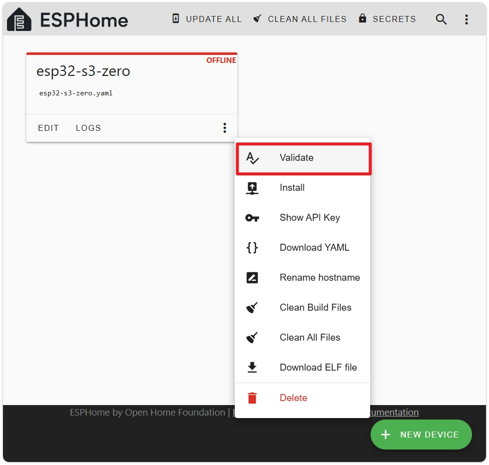
After editing, click the Validate button to verify the YAML syntax.
3.2 !secret and secrets.yaml
!secret xxx is a special ESPHome syntax meaning "read the value of key xxx from secrets.yaml."
The Wi-Fi credentials entered in wizard step 4 are automatically written to secrets.yaml:
# secrets.yaml
wifi_ssid: MyHomeWiFi
wifi_password: my-wifi-password
Referenced in the device YAML:
wifi:
  ssid: !secret wifi_ssid
  password: !secret wifi_password
To change Wi-Fi credentials, edit them directly in secrets.yaml:
Centralizing sensitive information in secrets.yaml allows multiple devices to share the same credentials, and prevents password leakage when exporting or sharing device configurations.
4. Add the Onboard RGB LED
The ESP32-S3-Zero's onboard RGB LED is on GPIO21, type WS2812 (single NeoPixel). In ESPHome, it is driven via the esp32_rmt_led_strip platform under light.
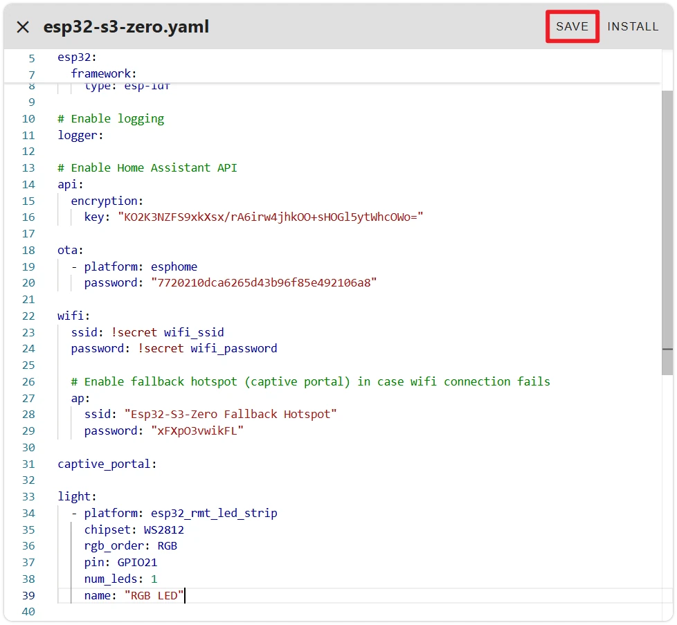
Append the following section to the end of the wizard-generated YAML:
light:
  - platform: esp32_rmt_led_strip
    chipset: WS2812
    rgb_order: RGB
    pin: GPIO21
    num_leds: 1
    name: "RGB LED"
Field descriptions:
platform: esp32_rmt_led_strip— Uses the ESP32's RMT peripheral to drive WS2812-compatible LED strips (single LEDs use the same driver).chipset: WS2812— LED protocol type.rgb_order: RGB— The ESP32-S3-Zero's onboard RGB LED has a fixed Red, Green, Blue data order.pin: GPIO21— The data pin for the RGB LED on the ESP32-S3-Zero.num_leds: 1— Only one LED onboard.name: "RGB LED"— The entity name displayed in HA.
For complete field documentation, see ESPHome esp32_rmt_led_strip documentation.
After adding, click SAVE in the top-right corner of the editor, then click INSTALL to begin the flashing process.
5. Compile and First Flash
The first flash must be done via USB — Wirelessly (OTA) only becomes available after the device has been flashed once and connected to Wi-Fi.
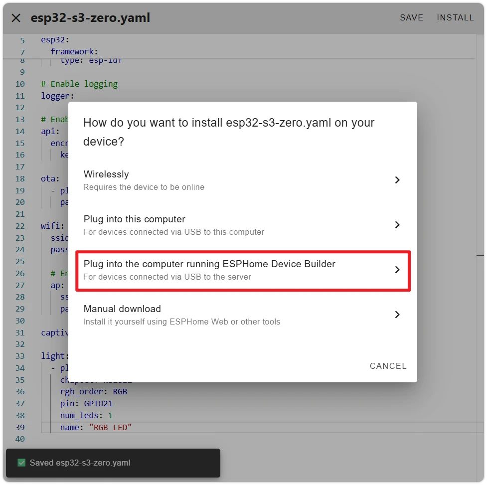
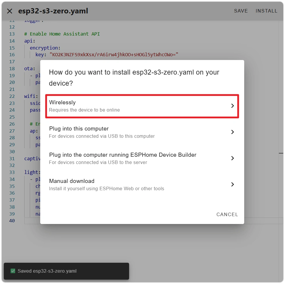
After clicking INSTALL, a popup lists several flashing methods:
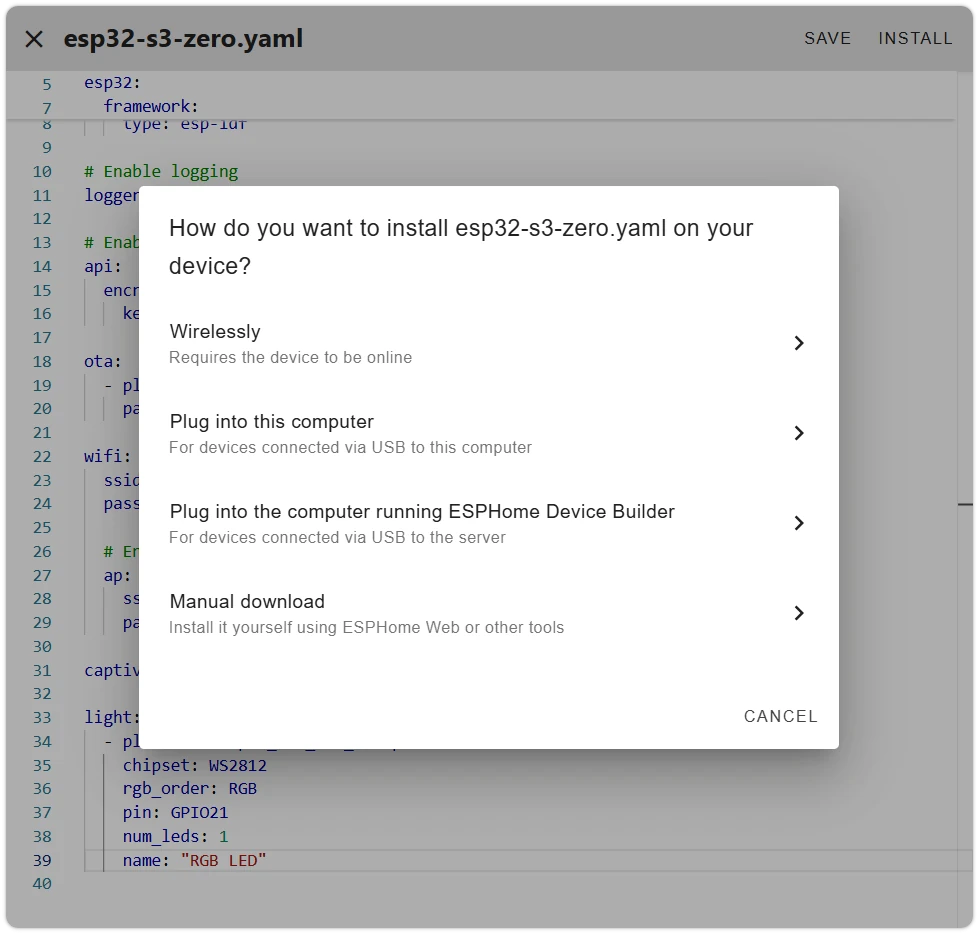
- Wirelessly — OTA update via Wi-Fi, requires the device to already be online. For the first flash, the device has no firmware, so this option is unavailable.
- Plug into this computer — The device's USB is plugged into "the computer you are currently browsing from," and the browser flashes via Web Serial.
- Plug into the computer running ESPHome Device Builder — The device's USB is plugged into "the host/server running ESPHome," which flashes directly from the server side.
- Manual download — Downloads the firmware binary for manual flashing using ESPHome Web tool or
esptool.
Plug into this computer relies on the browser's Web Serial API, which is only available over HTTPS (secure context). Self-hosted Home Assistant pages are typically accessed via HTTP, so this method is unavailable in most self-hosted environments.
Regardless of the method used, the first compilation takes a long time (several minutes to 10+ minutes depending on network and host performance). ESPHome needs to download the toolchain, build framework, and dependencies. Subsequent compilations are significantly faster. Progress may appear to stall temporarily during compilation — this is expected.
Below are two viable methods — choose one based on your environment:
- ESPHome Web Tool (Recommended)
- VM Flashing (Device Builder)
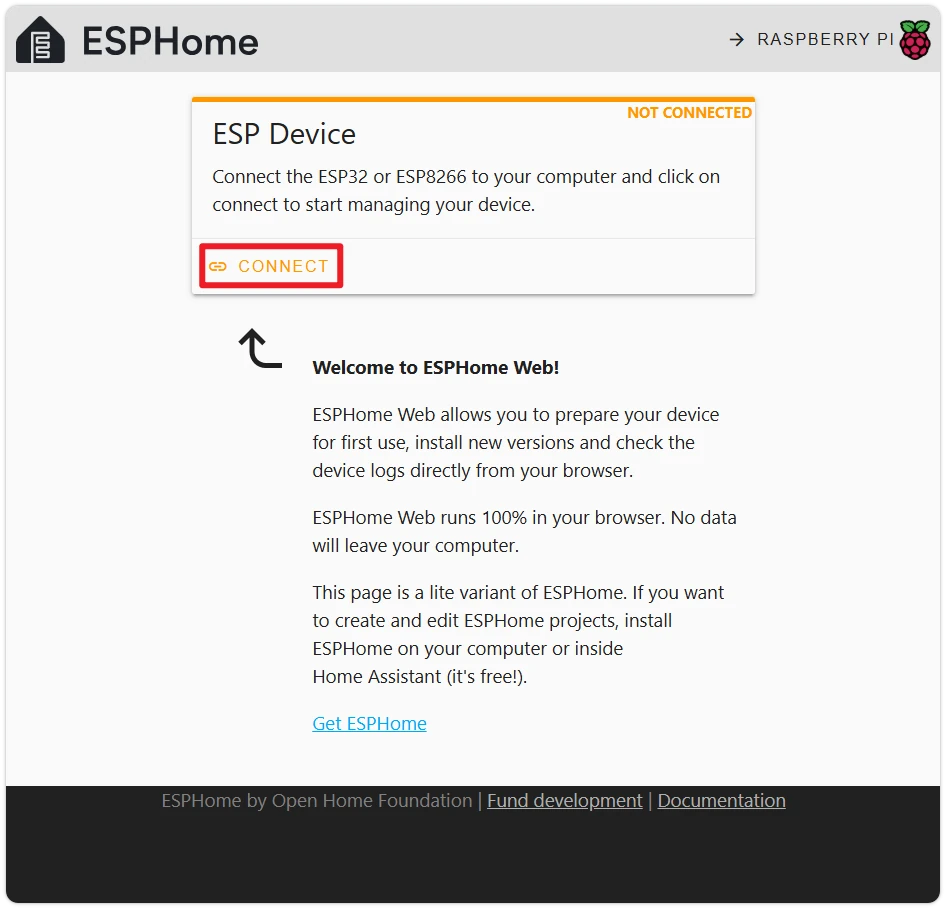
ESPHome Web is an official browser-based flashing tool that runs on an HTTPS site, allowing direct USB flashing to the device. Requires Chrome or Edge browser.
-
In the popup, select Manual download. The window will show the build log — wait patiently for firmware compilation to complete.
After compilation, select Factory format to download a
.binfirmware file, then close the window.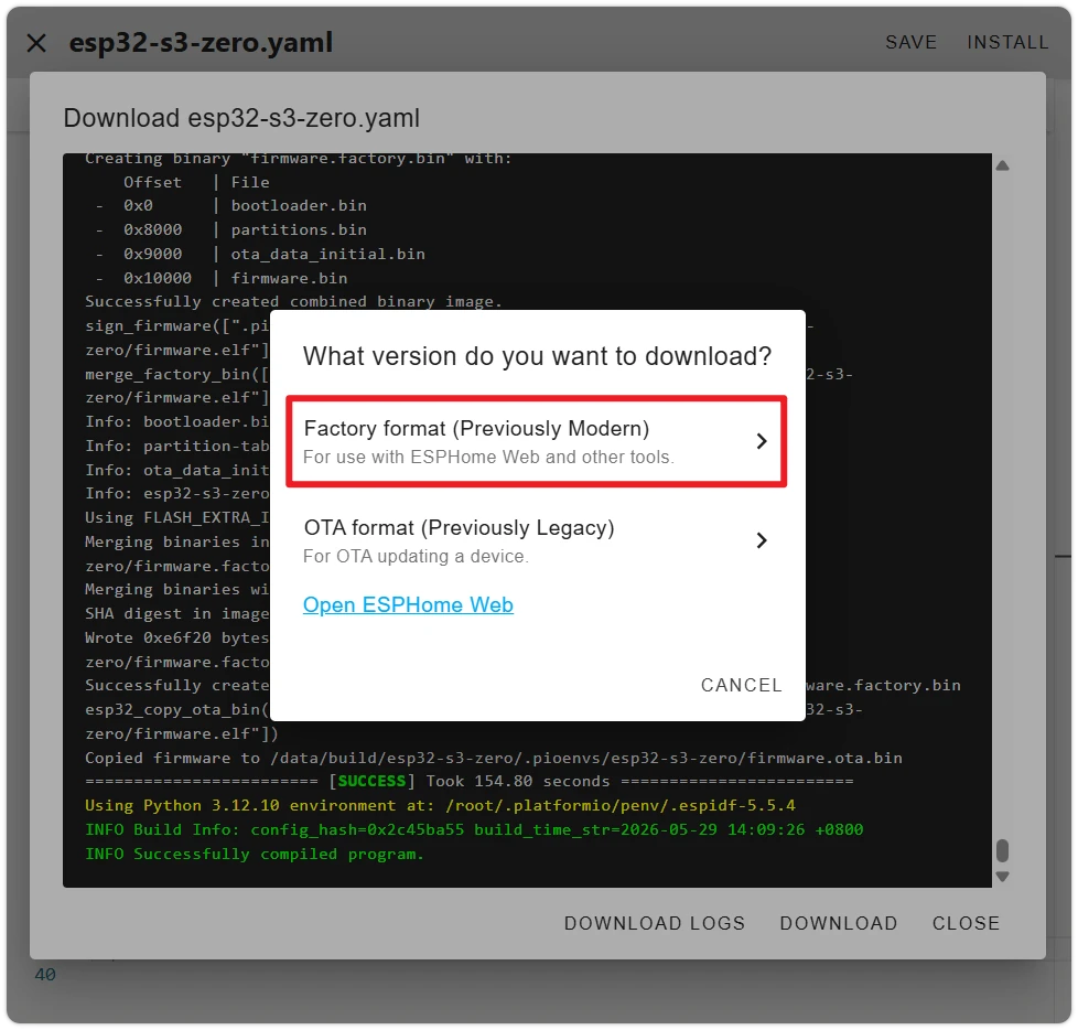
-
Open ESPHome Web and click Connect.
-
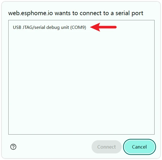
The browser will show a "Select a serial port" dialog. Find the port corresponding to the ESP32-S3-Zero (usually displayed as
USB JTAG/serial debug unitor with ESP32-S3 in the name), and click to connect.If Flashing Fails or No Port Is VisibleIn most cases, simply plugging in the USB will allow direct flashing. If it fails or no port is visible, unplug the USB, then hold the BOOT button while plugging in the USB. Release BOOT after the device is recognized, and try flashing again.
-
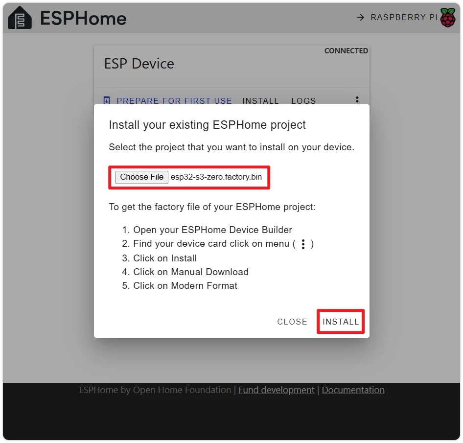
Click Install, select the
.binfile downloaded in step 1, and flashing begins.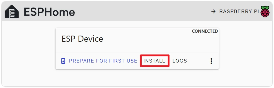
-
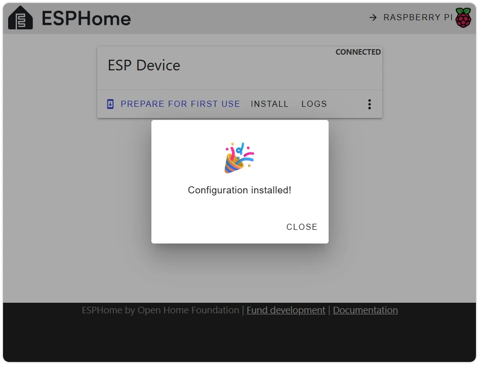
Flash successful.
Let the host running ESPHome flash directly. When Home Assistant runs in a VM, you need to pass through the USB device to the VM in VMware first — otherwise the VM cannot access the host's USB ports.
-
Plug the ESP32-S3-Zero into the host's USB port.
-
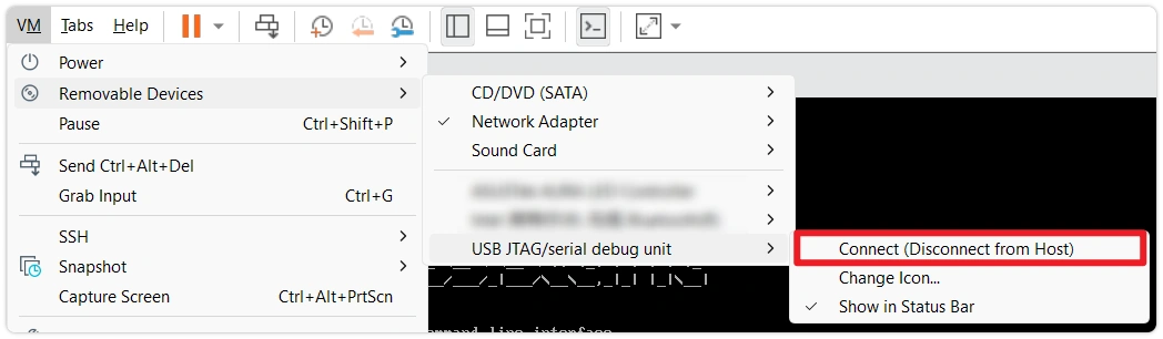
In the VMware Workstation top menu VM → Removable Devices, find the ESP32-S3 entry and click Connect (Disconnect from Host).
-
In the popup, select Plug into the computer running ESPHome Device Builder.
-
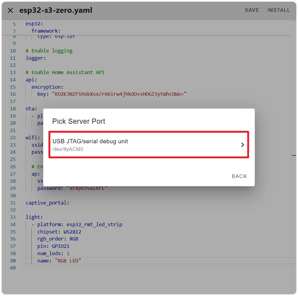
ESPHome will list the serial ports recognized on the server side. Select the port corresponding to the ESP32-S3-Zero and continue.
If Flashing Fails or No Port Is VisibleIn most cases, simply plugging in the USB will allow direct flashing. If it fails or no port is visible, unplug the USB, then hold the BOOT button while plugging in the USB. Release BOOT after the device is recognized, and try flashing again.
-
When the log shows
Successfully uploaded program., flashing is complete and the device runtime logs will start printing.After seeing
[I][safe_mode:142]: Boot seems successful; resetting boot loop counter, click STOP to close the log window.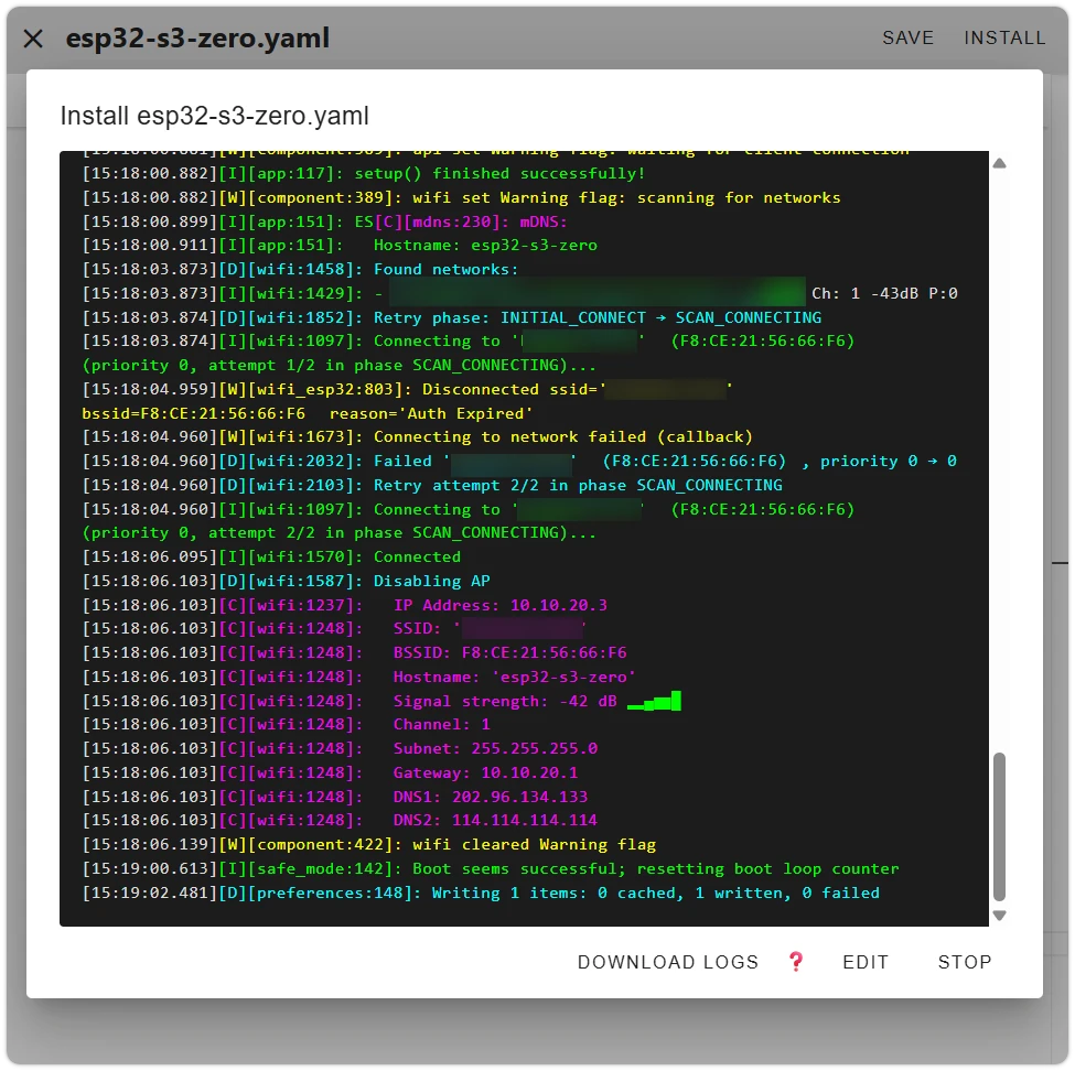
6. Pair the Device in Home Assistant
After flashing successfully and connecting to Wi-Fi, ESPHome broadcasts itself via mDNS, and HA will automatically discover the device.
-
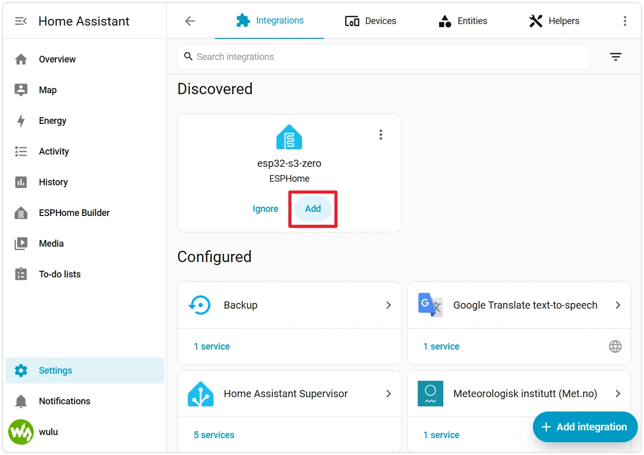
Switch to the HA main interface and click Settings → Devices & Services. In the "Discovered" section, you should see "esp32-s3-zero ESPHome."
Click Add — HA will automatically retrieve the encryption key via mDNS. Just click Submit.
 ESPHome Device Not Appearing in Discovered?
- Confirm the device and HA host are on the same subnet.
- Add manually: Settings → Devices & Services → Add Integration → ESPHome, enter the hostname
esp32-s3-zero.localor the device's IP address. The device IP can be found in the ESPHome app's LOGS.
-
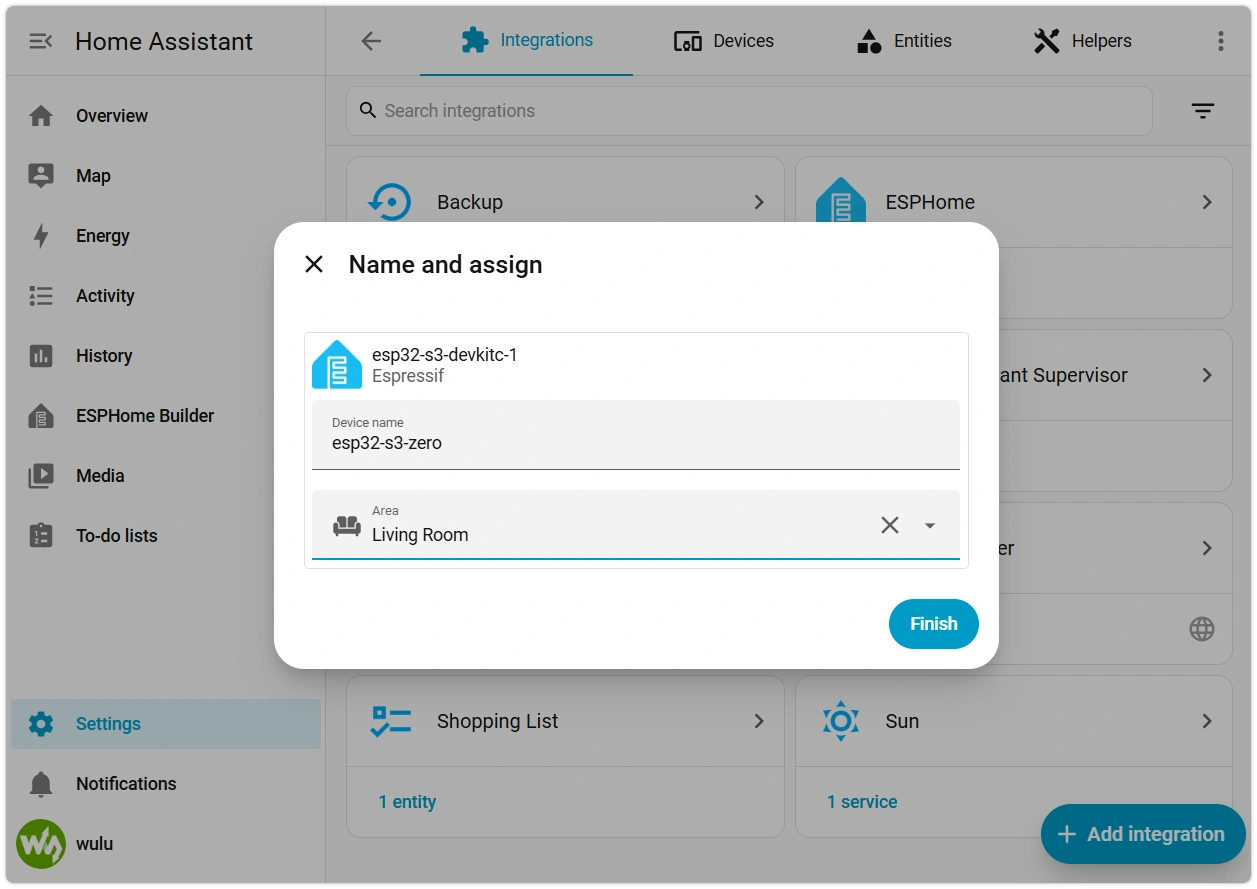
Once submitted, HA will ask you to assign the device to an area (e.g., "Living Room"). Select an area and click Finish.
-
After successful pairing, HA will redirect to the device page. You can also go to Settings → Devices & Services → ESPHome, find
esp32-s3-zero, which contains a light entity named RGB LED. Toggle the switch to turn on the light — the onboard LED will light up.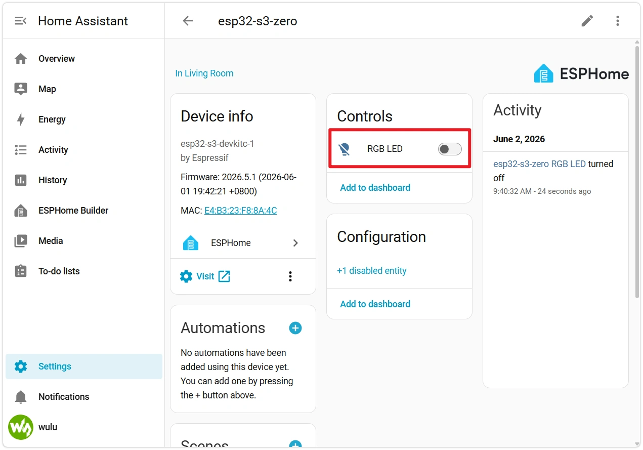
-
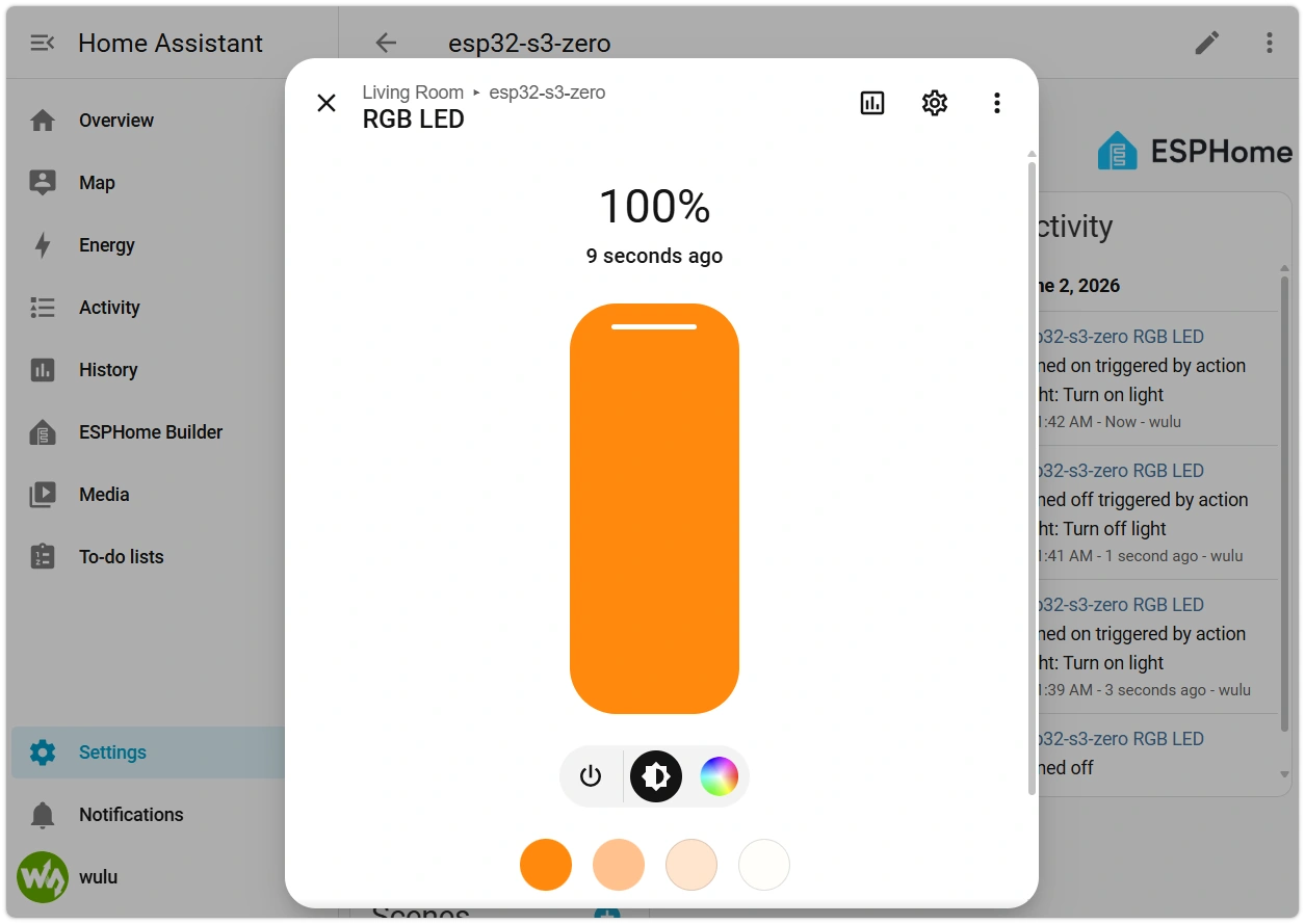
Click the RGB LED entity to open the control panel. Drag the color picker or brightness slider, and the onboard LED will change in real time.
-
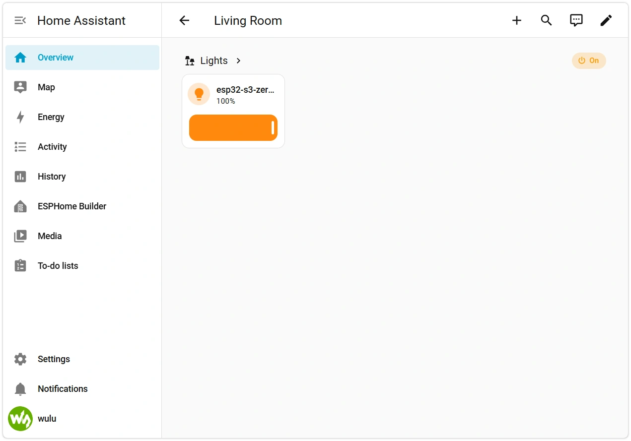
You can also find the RGB LED entity in Overview → Living Room → Lights and control the LED via the color picker.
The ESP32 is now a light device in HA.
You've now completed the full workflow: YAML editing → flashing → HA pairing → remote control.
7. Subsequent Changes: OTA Updates
The device is now online and includes the OTA module — future YAML changes no longer require USB.
-
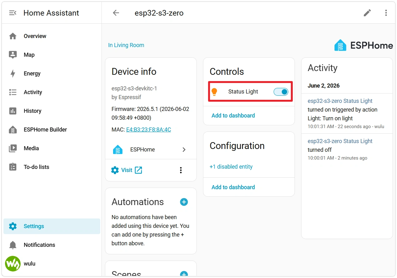
Edit the device configuration in the ESPHome app, for example, change the LED name from
"RGB LED"to"Status Light", and save. -
Click INSTALL → select Wirelessly.
 Restart Risk Within 1 Minute After OTA
The
ota:component automatically enables safe mode. After the new firmware boots, it runs a 1-minuteboot_is_good_aftertimer. If any restart occurs before the timer expires (manual RESET, power loss, crash), the next boot will be rolled back to the previous firmware by the ESP-IDF bootloader. After the timer expires, the firmware marks itself as "confirmed good," and subsequent restarts will no longer trigger rollback. When LOGS showBoot seems successful, the new firmware is confirmed.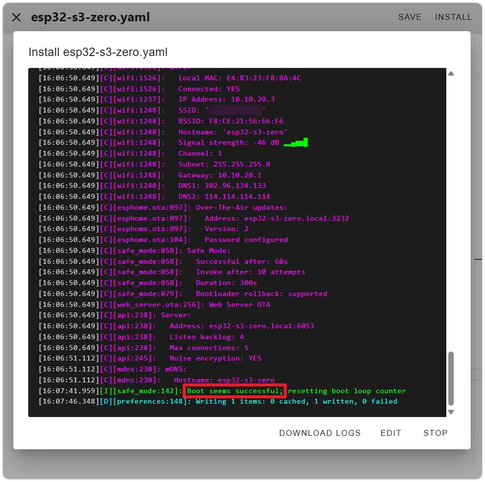
This rollback mechanism relies on the esp-idf framework (which is what this section's YAML uses:
framework: esp-idf). Behavior differs under the arduino framework. For details, see the ESPHome Safe Mode documentation. -
ESPHome will compile the new firmware, push it to the device via Wi-Fi, and automatically restart. The entity name in HA will also update accordingly.
Common reasons for OTA failure:
- Device offline: Check the device status on the ESPHome app main page — gray indicates offline. Resolve the Wi-Fi issue before attempting OTA.
- OTA password mismatch: The wizard-generated password is in the YAML's
ota.password. If you manually changed this field but didn't flash the new firmware, OTA will be rejected by the device.
If OTA failure causes the device to be unable to boot or connect to Wi-Fi, you can reflash via USB to recover.
8. Common Issues in This Section
- Compilation error
YAML syntax error: Indentation error. Check if tabs and spaces are mixed, and whether alignment is consistent. - Compilation error
Unable to find component xxx: Component name is misspelled, or the current ESPHome version does not include that component. Verify the exact name in the ESPHome Components Directory. - No device port visible during flashing: Not in download mode (see Section 5 "If Flashing Fails or No Port Is Visible"), or the host cannot recognize the USB device (try a different cable or USB port). When flashing via VM, also confirm the USB device has been assigned to the VM in VMware.
- LED does not light up after flashing: Check if
rgb_orderis set toRGB. Use the HA color picker rather than just the brightness slider (brightness at 100% with color set to black still results in the LED being off). - HA does not automatically discover the device: See the tip in Section 6, step 1. You can also check the ESPHome device LOGS to confirm whether Wi-Fi and API connection succeeded.
- OTA failure
Connection refused: The OTA password in the firmware on the device does not match the current YAML — reflash via USB to synchronize. - HA shows entity "unavailable" but ESPHome shows device ONLINE: OTA safe rollback was triggered — a restart within 1 minute of the new firmware causes the bootloader to roll back to the previous version. Search for
OTA rollback detectedin LOGS to confirm. Reflash via USB to recover. See the warning in Section 7 for details.