Working with ESP-IDF
This chapter contains the following sections. Please read as needed:
- ESP-IDF Getting Started
- Setting Up Development Environment
- Running Official Espressif Examples
- Erasing Device Flash
ESP-IDF Getting Started
New to ESP32 ESP-IDF development and looking to get started quickly? We have prepared a general Getting Started Tutorial for you.
- Section 1: Environment Setup
- Section 2: Running Examples
- Section 3: Creating a Project
- Section 4: Using Components
- Section 5: Debugging
- Section 6: FreeRTOS
- Section 7: Peripherals
- Section 8: Wi-Fi Programming
- Section 9: BLE Programming
Please Note: This tutorial uses the ESP32-S3-Zero as a teaching example, and all hardware code is based on its pinout. Before you start, it is recommended that you check the pinout of your development board to ensure the pin configuration is correct.
Setting Up the Development Environment
Note: ESP-IDF supports ESP32-H2 starting from version V5.1. ** When installing ESP-IDF, you must select version V5.1 or later.**
The following guide uses Windows as an example, demonstrating development using VS Code + the ESP-IDF extension. macOS and Linux users should refer to the official documentation.
The screenshots in this section use ESP-IDF V5.5.2 as an example. When installing, please select the ESP-IDF version that matches your board's example.
Install the ESP-IDF Development Environment
-
Download the installation manager from the ESP-IDF Installation Manager page. This is Espressif's latest cross-platform installer. The following steps demonstrate how to use its offline installation feature.
Click the Offline Installer tab on the page, then select Windows as the operating system and the ESP-IDF version you need (the version shown in the screenshot is for reference only — choose the version that fits your actual needs).

After confirming your selection, click the download button. The browser will automatically download two files: the ESP-IDF Offline Package (.zst) and the ESP-IDF Installer (.exe).

Please wait for both files to finish downloading.
-
Once the download is complete, double-click to run the ESP-IDF Installer (eim-gui-windows-x64.exe).
The installer will automatically detect if the offline package exists in the same directory. Click Install from archive.

Next, select the installation path. We recommend using the default path. If you need to customize it, ensure the path does not contain Chinese characters or spaces. Click Start installation to proceed.

-
When you see the following screen, the ESP-IDF installation is successful.

-
We recommend installing the drivers as well. Click Finish installation, then select Install driver.

Install Visual Studio Code and the ESP-IDF Extension
-
Download and install Visual Studio Code.
-
During installation, it is recommended to check Add "Open with Code" action to Windows Explorer file context menu to facilitate opening project folders quickly.
-
In VS Code, click the Extensions icon
 in the Activity Bar on the side (or use the shortcut Ctrl + Shift + X) to open the Extensions view.
 -
Enter ESP-IDF in the search box, locate the ESP-IDF extension, and click Install.

-
For ESP-IDF extension versions ≥ 2.0, the extension will automatically detect and recognize the ESP-IDF environment installed in the previous steps, requiring no manual configuration.
Running Official Espressif Examples
Please refer to Waveshare ESP-IDF Getting Started - Section 2 Run Example.
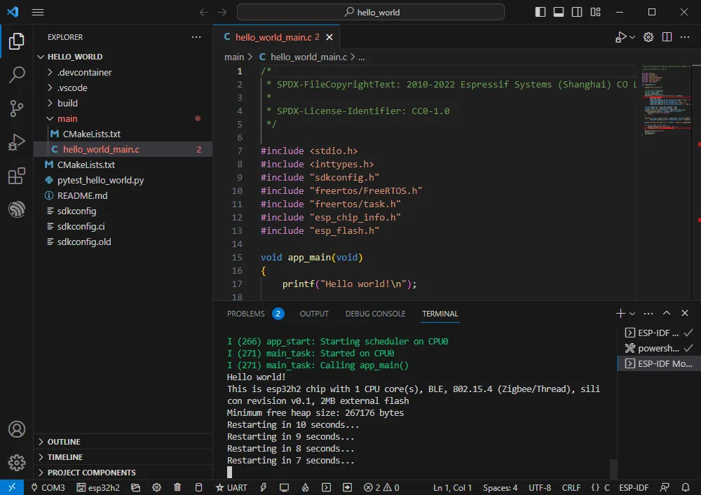
Hello Word
- Official example path: get-started -> hello_world
- Example effect: Outputs "Hello world!" at 10-second intervals in the TERMINAL window.
Software Operation
-
Create the official hello_world example following the tutorial above.
-
The program is compatible with ESP32-H2; no modification needed.
-
Set the COM port and driver target (it is recommended to use the COM port corresponding to USB; you can check it in Device Manager), then click compile and flash to run the program.
GPIO
- Official example path: peripherals -> gpio -> generic_gpio
- Example effect: LED blinks at 1-second intervals.
Hardware Connection
| ESP32-H2 | LED |
|---|---|
| GPIO18 (or GPIO19) | LED+ |
| GND | LED- |
Software Operation
-
Create the official generic_gpio example following the tutorial above.
-
The program is compatible with ESP32-H2; no modification needed.
-
Set the COM port and driver target (it is recommended to use the COM port corresponding to USB; you can check it in Device Manager), then click compile and flash to run the program.
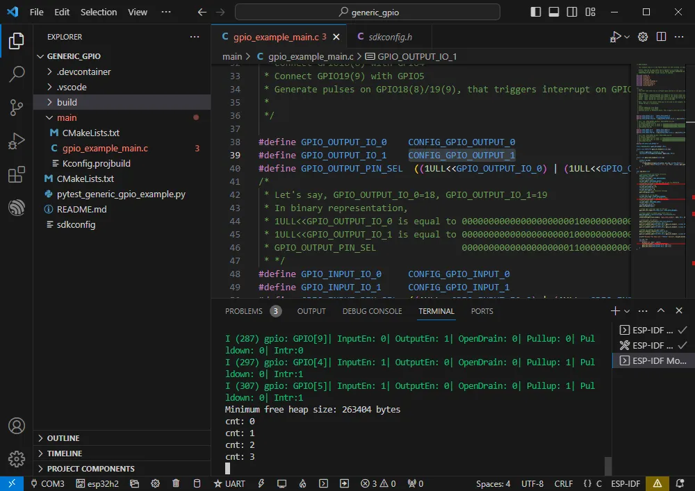
-
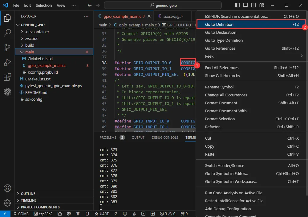
Go to the macro definition location in the program to see which GPIO is actually used.
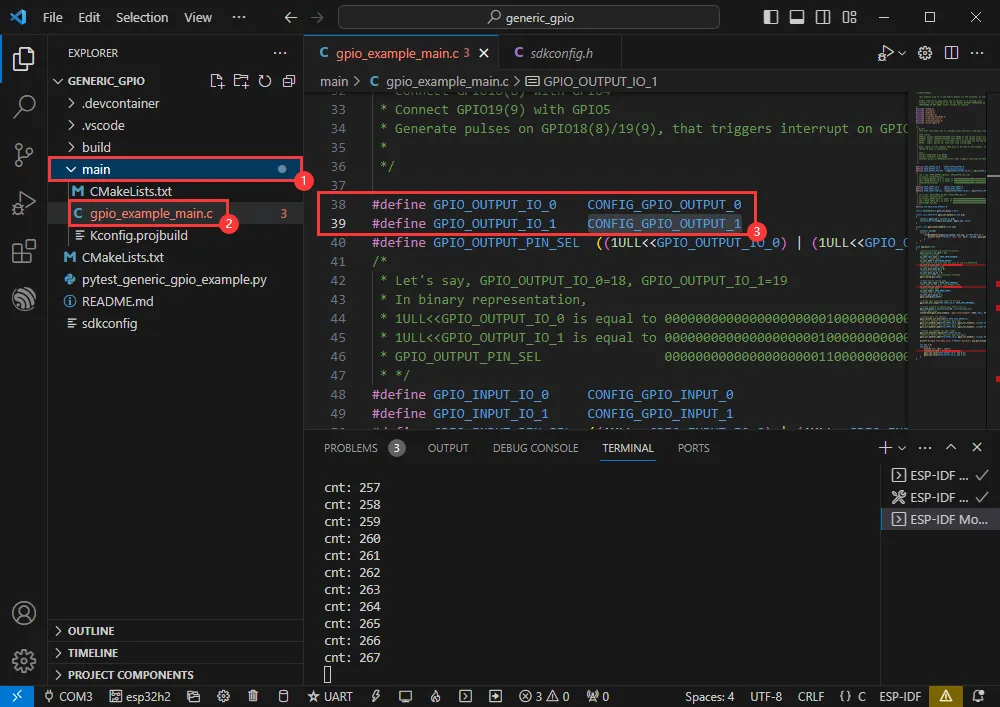
-
Right-click and go to the GPIO definition location.
-
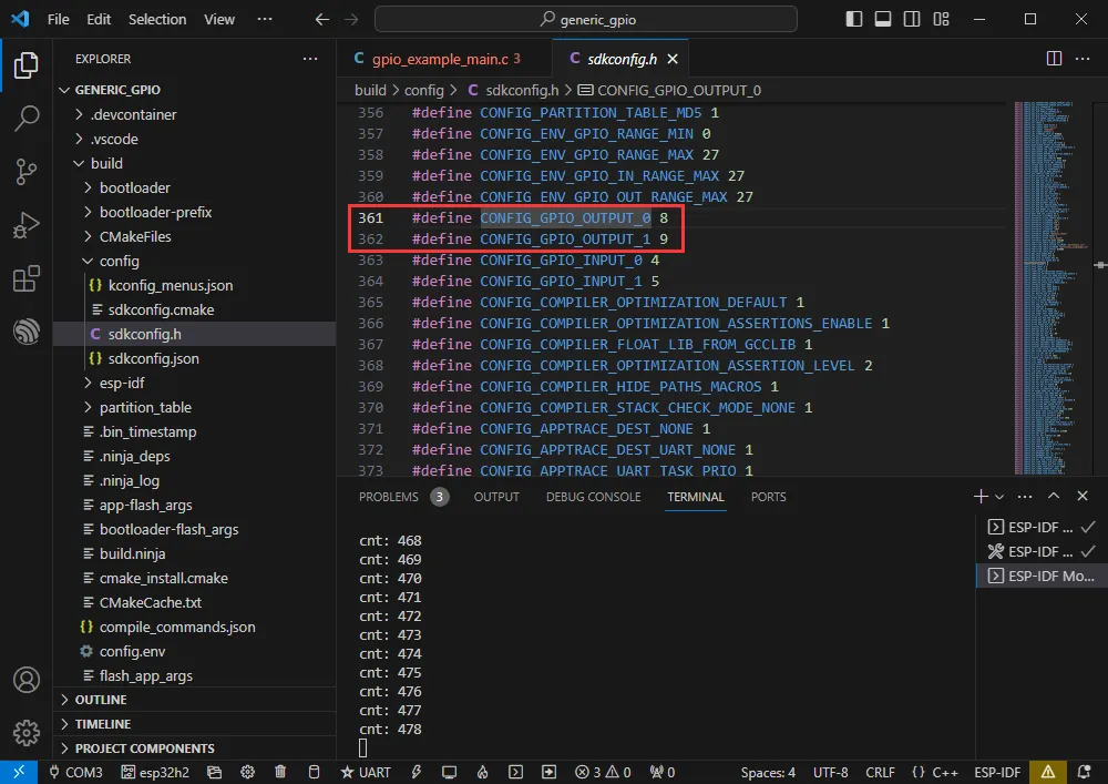
The actual GPIOs used are GPIO8 and GPIO9.
RGB
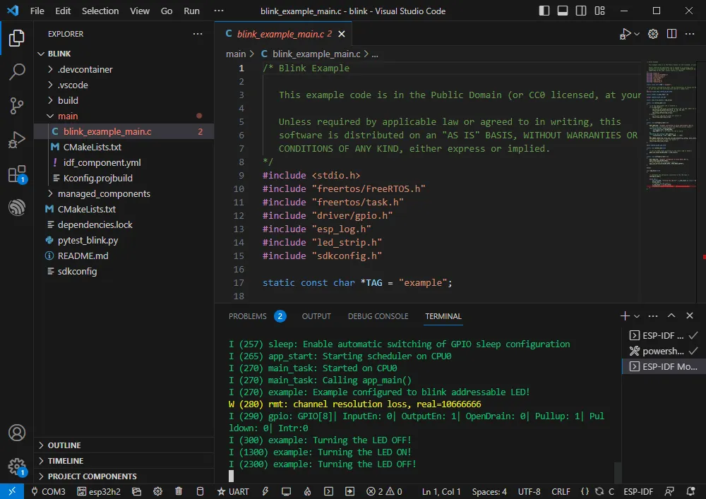
- Official example path: get-started -> blink
- Example effect: The onboard RGB LED blinks at 1-second intervals.
Software Operation
-
Create the official blink example following the tutorial above.
-
The program is compatible with ESP32-H2; no modification needed.
-
Set the COM port and driver target (it is recommended to use the COM port corresponding to USB; you can check it in Device Manager), then click compile and flash to run the program.
UART
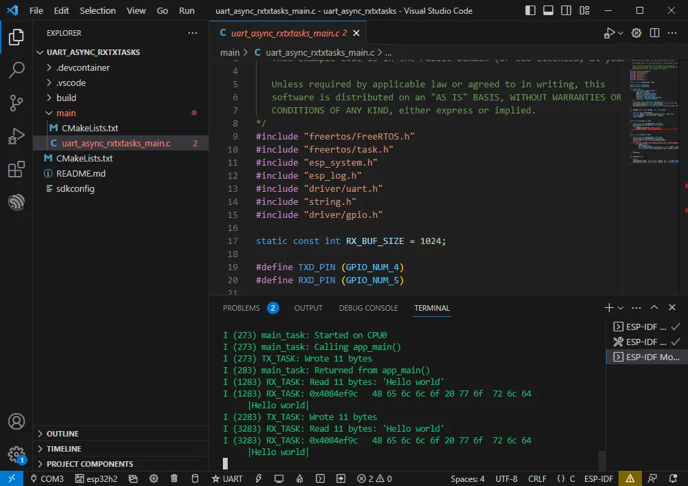
- Official example path: peripherals -> uart -> uart_async_rxtxtasks
- Example effect: Self-transmission and reception of UART data when GPIO4 and GPIO5 are shorted.
Hardware Connection
| ESP32-H2 | ESP32-H2 (Same Board) |
|---|---|
| GPIO4 | GPIO5 |
Software Operation
-
Create the official uart_async_rxtxtasks example following the tutorial above.
-
The program is compatible with ESP32-H2; no modification needed.
-
Set the COM port and driver target (it is recommended to use the COM port corresponding to USB; you can check it in Device Manager), then click compile and flash to run the program.
-
Make the hardware connection according to the GPIOs used.
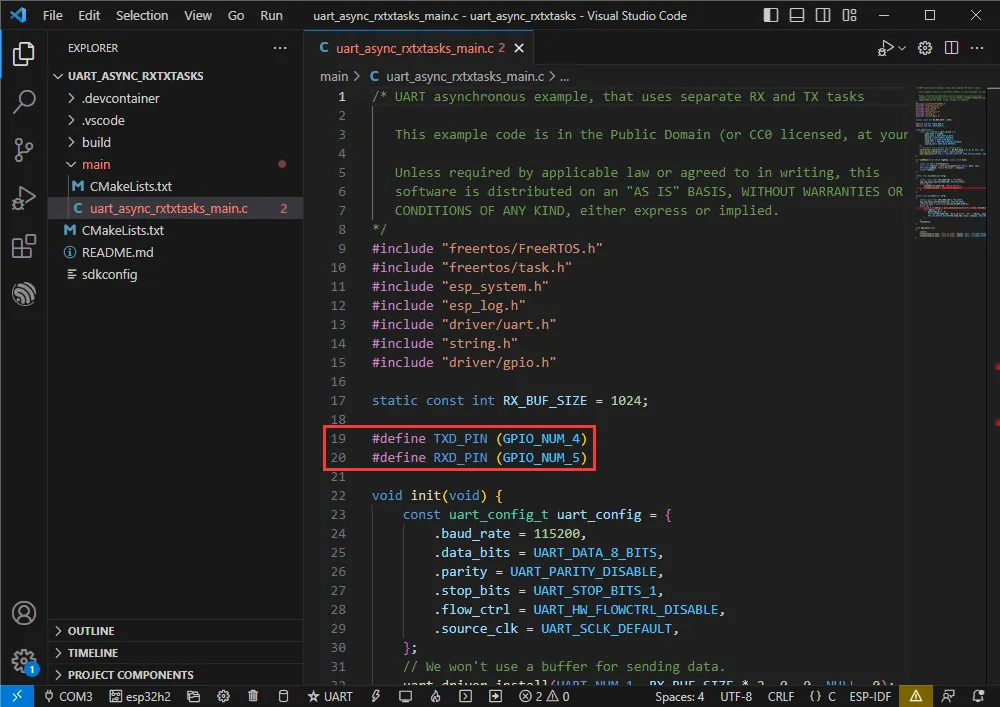
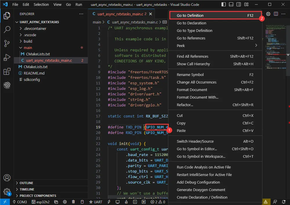
-
You can go to the definition file to see the actual GPIOs used (select GPIO_NUM_4 -> right-click -> Go to Definition).
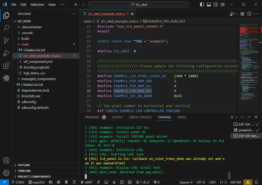
I2C
- Official example path: peripherals -> lcd -> i2c_oled
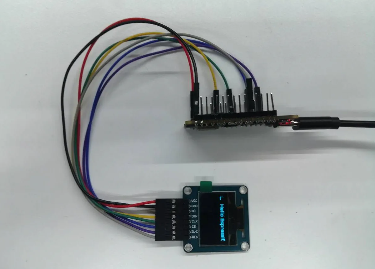
- Example effect: Lights up a 0.96inch OLED (A) and displays a string of characters.
Hardware Connection
| 0.96inch OLED (A) | ESP32-H2 |
|---|---|
| VCC | 3V3 |
| GND | GND |
| DIN | GPIO3 |
| CLK | GPIO4 |
| CS | GND |
| D/C | GND |
| RES | GPIO9 |
Software Operation
-
Create the official i2c_oled example following the tutorial above.
-
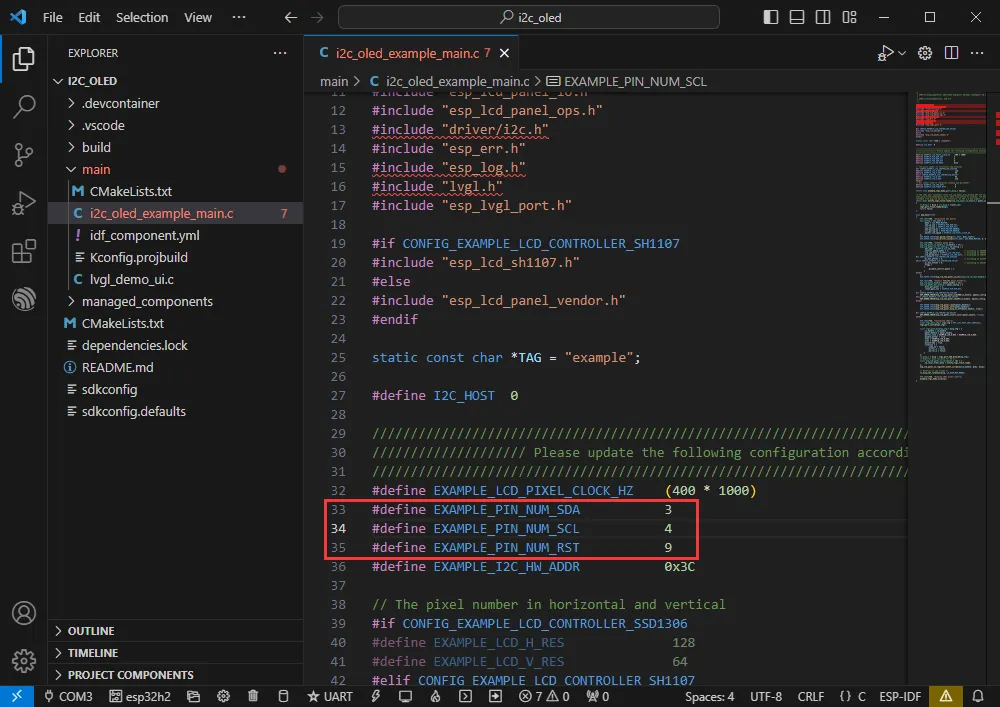
Modify the program to make it compatible with the 0.96inch OLED (A).
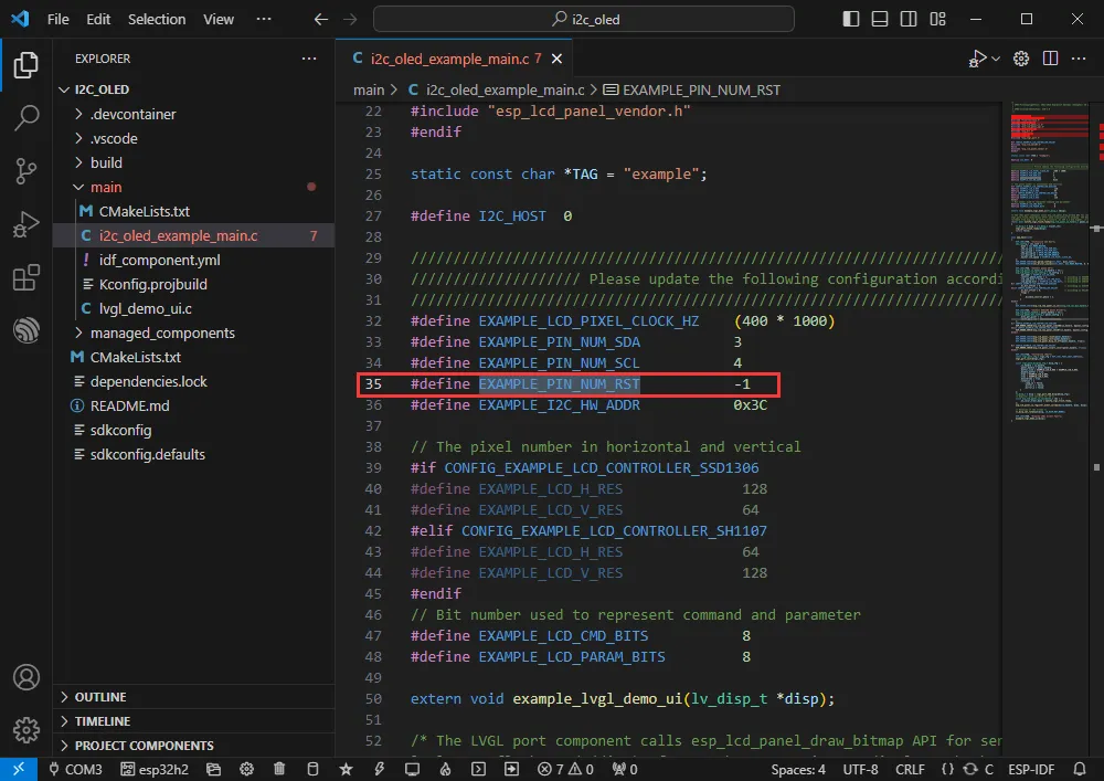
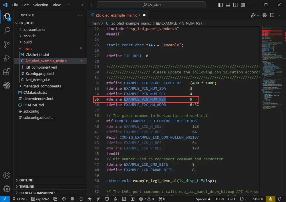
-
Adapt for the 0.96inch OLED (A); define the RES pin as GPIO9.
-
Set the COM port and target driver correctly (it is recommended to use the COM port corresponding to USB; you can check it in Device Manager) , then click Build and Flash to run the program.
-
The effect is as follows:
-
You can check the actual GPIOs used.
SPI
- Official example path: peripherals -> spi_master -> lcd
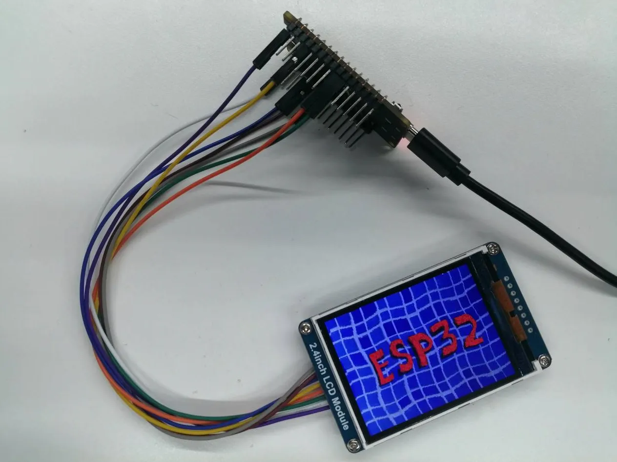
- Example effect: Dynamically displays images on a 2.4inch LCD Module.
Hardware Connection
| 2.4inch LCD Module | ESP32-H2 |
|---|---|
| VCC | 3V3 |
| GND | GND |
| DIN | GPIO5 |
| CLK | GPIO4 |
| CS | GPIO1 |
| D/C | GPIO10 |
| RES | GPIO11 |
| BL | GPIO12 |
Software Operation
-
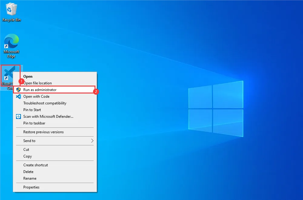
Right-click the VS Code icon and run VS Code as administrator.
-
Create the official lcd example following the tutorial above.
-
Modify the program to make it compatible with the 2.4inch LCD Module.
-
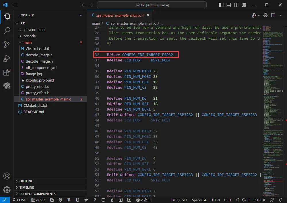
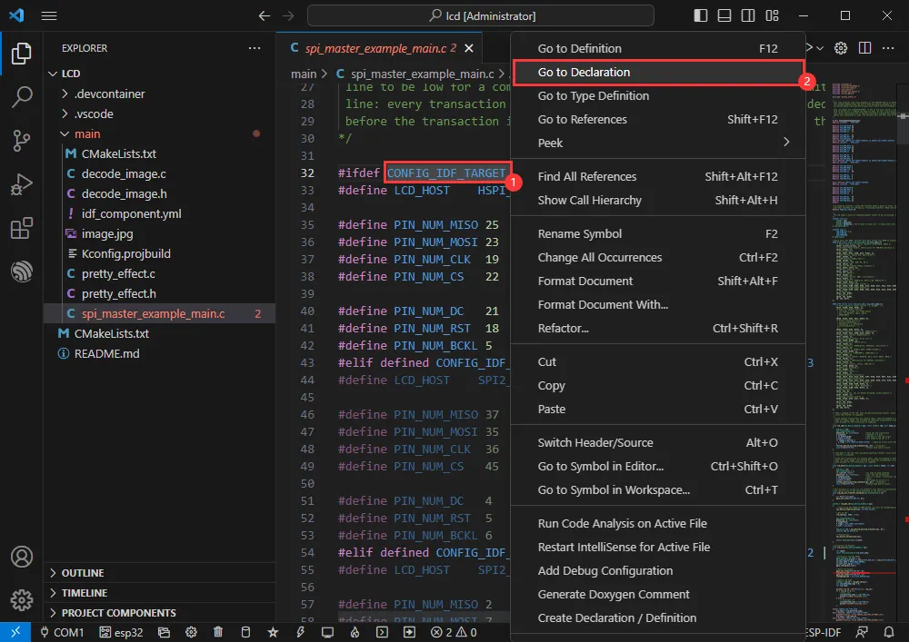
Jump to the definition location.
-
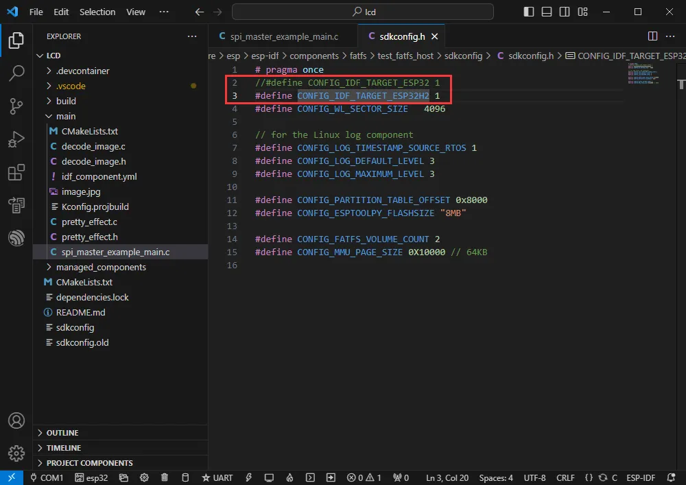
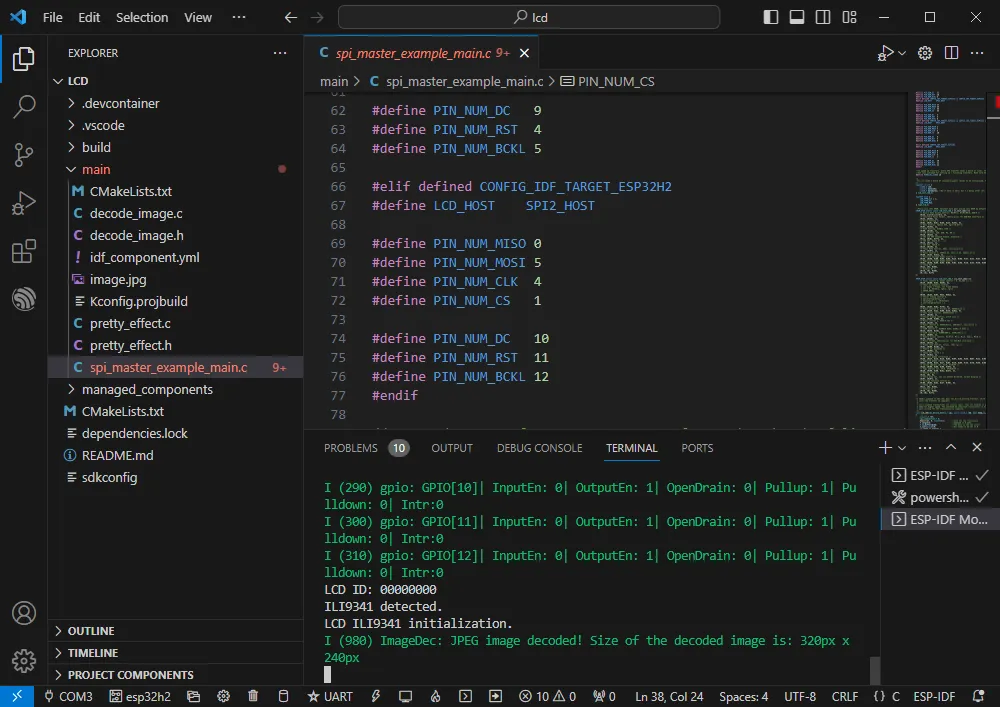
The current target is ESP32-H2; comment out definitions for other chips.

-
And define CONFIG_IDF_TARGET_ESP32H2 for ESP32-H2.
-
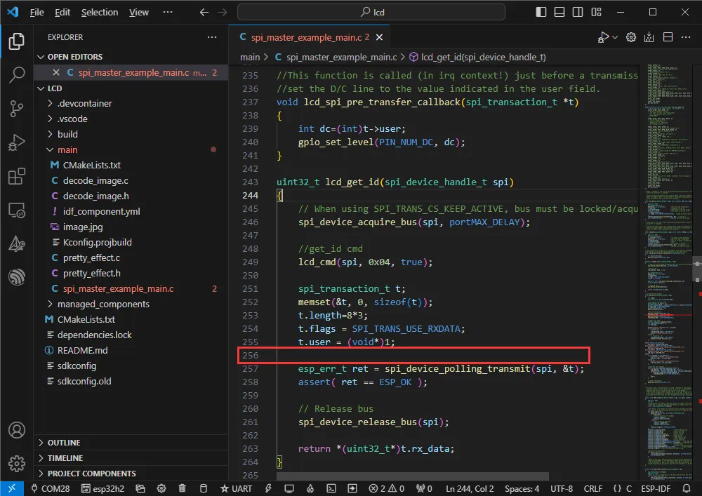
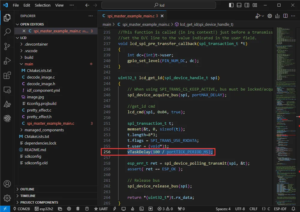
Wait for the ID read.
-
Add a read delay to prevent read failures.
-
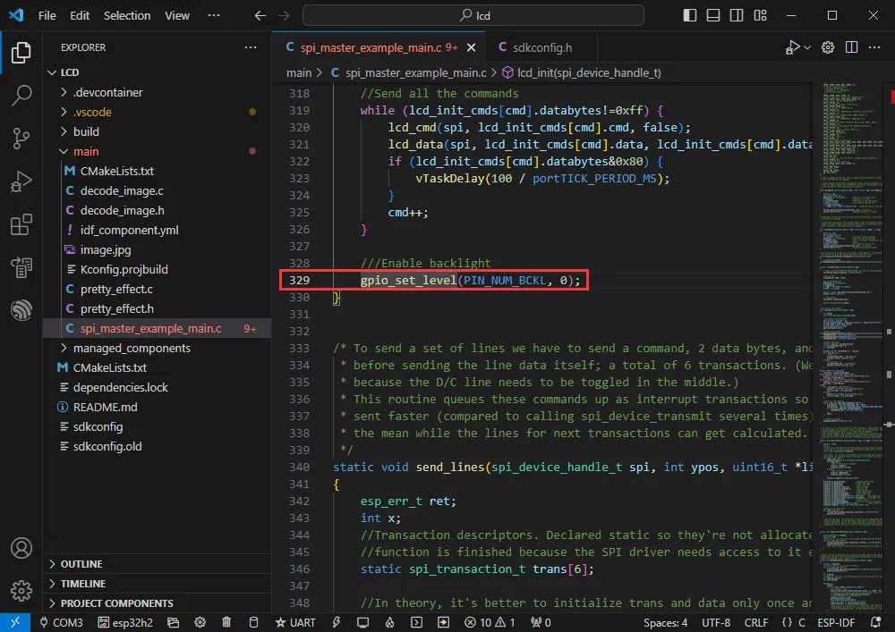
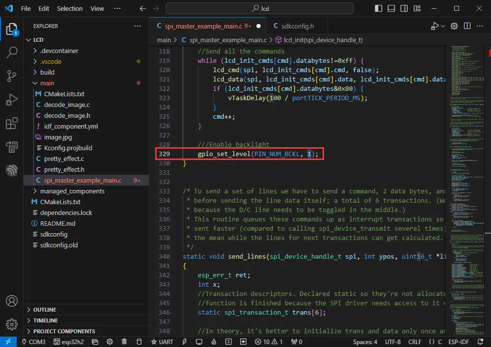
Modify the backlight control.
-
Change to gpio_set_level(PIN_NUM_BCKL, 1);.
-
Set the COM port and target driver correctly (it is recommended to use the COM port corresponding to USB; you can check it in Device Manager) , then click Build and Flash to run the program.
-
The effect is as follows:
Bluetooth
- Official example path: bluetooth -> bluedroid -> ble -> gatt_server
- Example effect: Data transfer between the ESP32-H2 and a Bluetooth debugging assistant on a mobile phone.
Software Operation
-
Install a Bluetooth debugging assistant on your phone.
-
Create the official gatt_server example following the tutorial above.
-
The program is compatible with ESP32-H2; no modification needed.
-
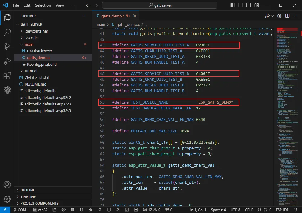
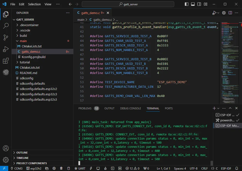
The Bluetooth name and UUID: the Bluetooth name is ESP_GATTS_DEMO.
-
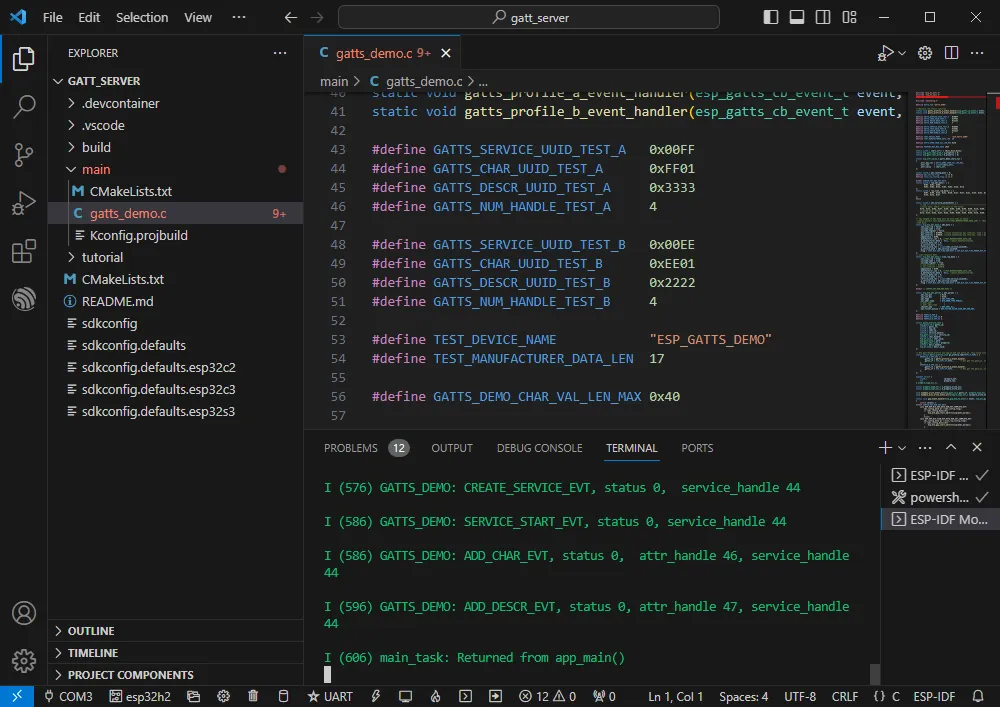
Set the COM port and target driver correctly (it is recommended to use the COM port corresponding to USB; you can check it in Device Manager) , then click Build and Flash to run the program.
-
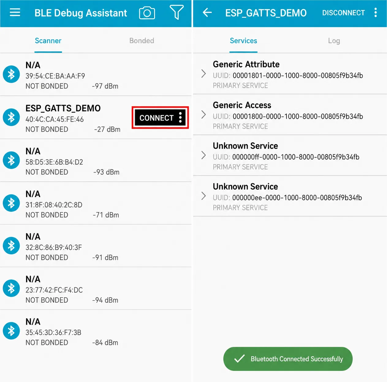
Connect to the ESP_GATTS_DEMO Bluetooth Bluetooth device on your phone.
-
Successful connection appears as shown below.
-
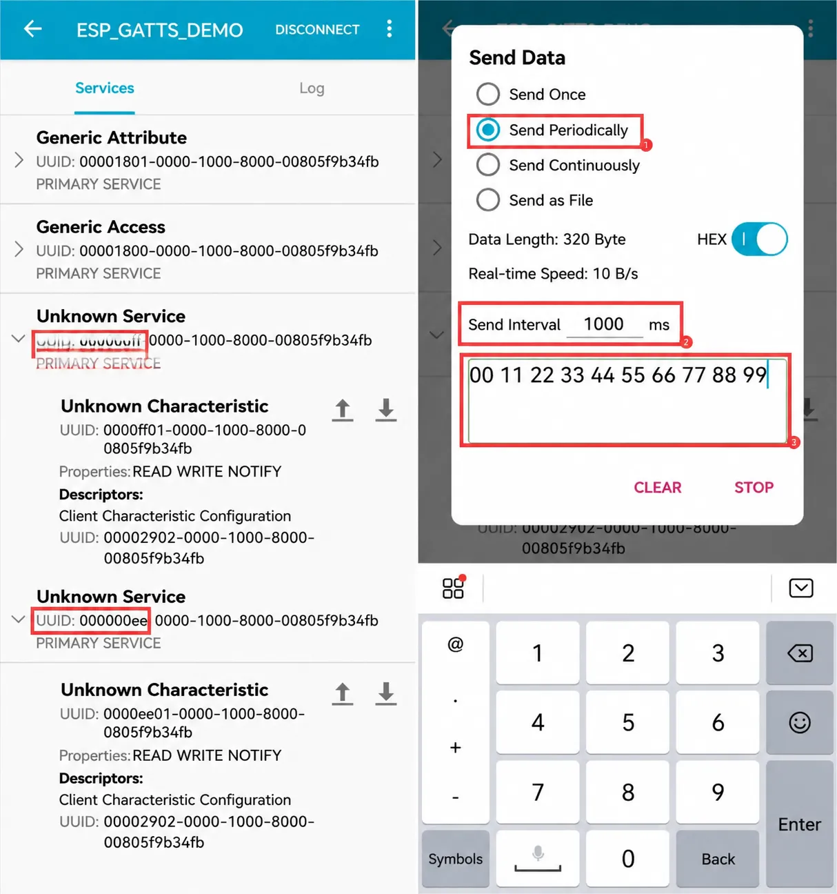
According to the UUID values in the program, the two servers below are available; choose one for uplink transmission.
-
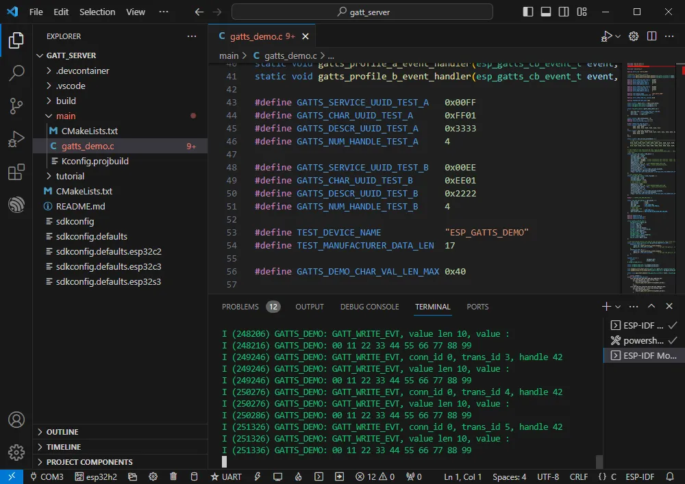
The ESP32-H2 receives the data.
Zigbee
- Official example 1 path: Zigbee -> light_sample -> HA_on_off_switch
- Official example 2 path: Zigbee -> light_sample -> HA_on_off_light
- Example effect: Two ESP32-H2 boards; one (flashed with the HA_on_off_switch program) uses its BOOT button to control the RGB LED on the other board.
Note: First flash the HA_on_off_switch program on one board, then flash the HA_on_off_light program on the other board.
Software Operation 1
-
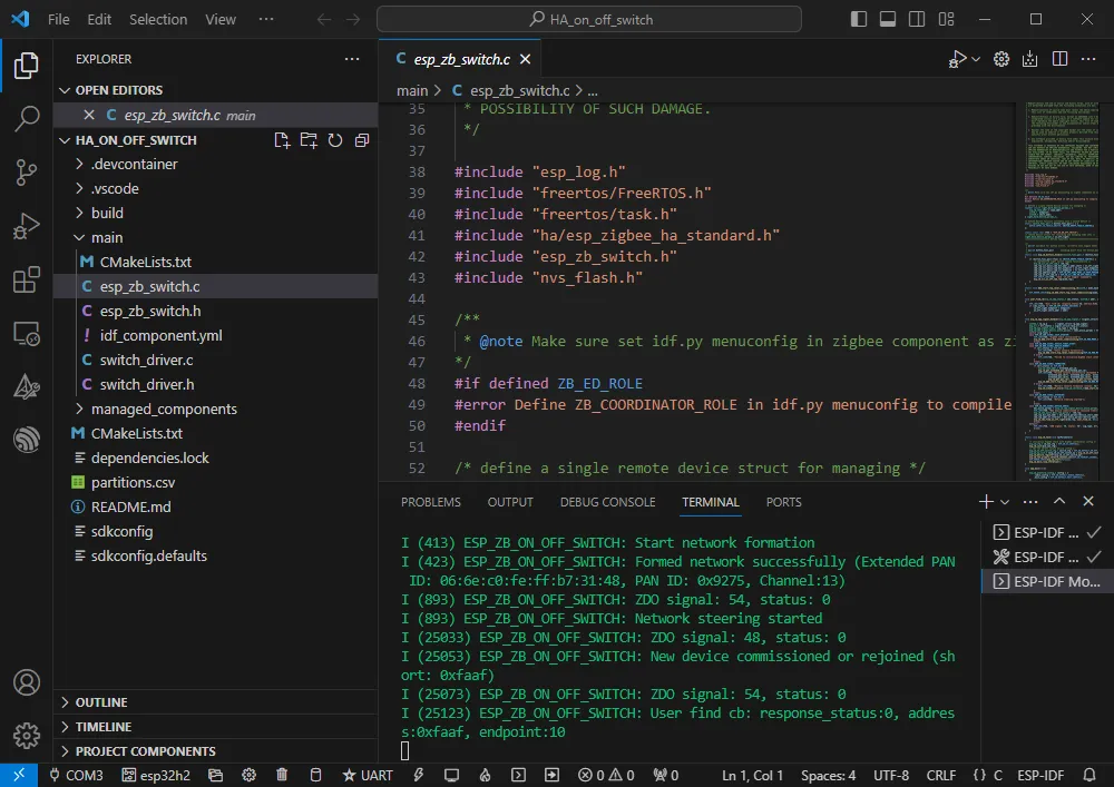
Create the official HA_on_off_switch example following the tutorial above.
-
The program is compatible with ESP32-H2; no modification needed.
-
Set the COM port and target driver correctly (use the COM port corresponding to UART; you can check it in Device Manager), then click Build and Flash to run the program.
Software Operation 2
-
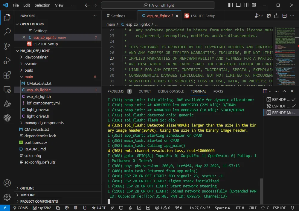
Create the official HA_on_off_light example following the tutorial above.
-
The program is compatible with ESP32-H2; no modification needed.
-
Set the COM port and driver target (use the COM port corresponding to UART), then click Build and Flash to run the program (wait a moment for the two chips to establish a connection).
-
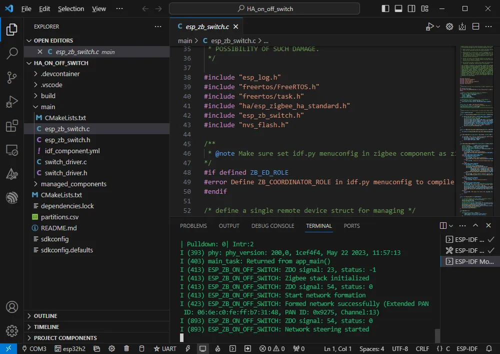
After a successful connection, the corresponding button program and LED program will print relevant data.
-
If initialization fails, it may be because the device still has residual network information. You can erase the device information and then re-form the network.
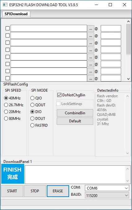
Erasing Device Flash
-
Extract the software resource package Flash debugging software
-
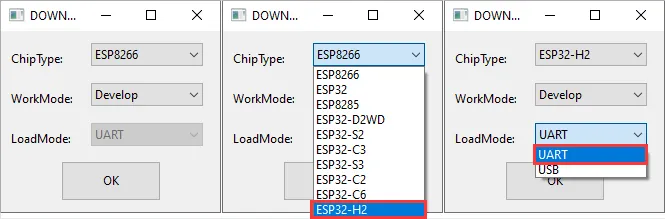
Open the flash_download_tool_3.9.5.exe software, select ESP32-H2 and UART
-
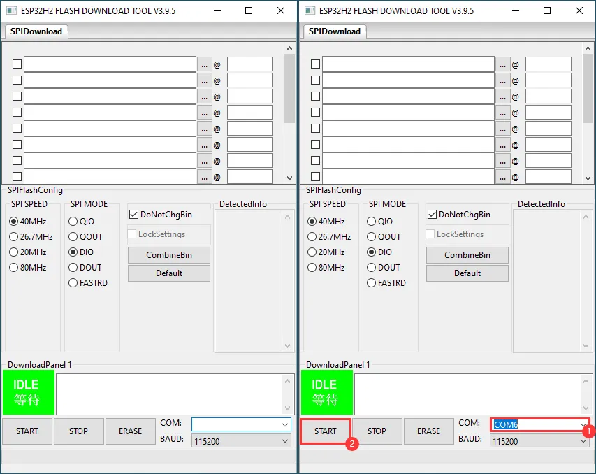
Select the UART port number, click START (do not select any bin file)
-
Wait for the flashing to complete, then click Erase
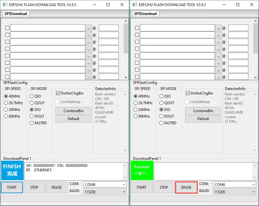
-
Wait for the erasing to complete