Working with Arduino
This chapter includes the following sections. Please read as needed:
Arduino Getting Started
New to Arduino ESP32 development and looking for a quick start? We have prepared a comprehensive Getting Started Tutorial for you.
- Section 0: Getting to Know ESP32
- Section 1: Installing and Configuring Arduino IDE
- Section 2: Arduino Basics
- Section 3: Digital Output/Input
- Section 4: Analog Input
- Section 5: Pulse Width Modulation (PWM)
- Section 6: Serial Communication (UART)
- Section 7: I2C Communication
- Section 8: SPI Communication
- Section 9: Wi-Fi Basics
- Section 10: Web Server
- Section 11: Bluetooth
- Section 12: LVGL GUI Development
- Section 13: Comprehensive Project
Note: This tutorial uses the ESP32-S3-Zero as a reference example, and all hardware code is based on its pinout. Before you start, we recommend checking the pinout of your development board to ensure the pin configuration is correct.
Setting Up the Development Environment
1. Installing and Configuring the Arduino IDE
Please refer to the tutorial Install and Configure Arduino IDE to download and install the Arduino IDE and add ESP32 support.
2. Additional Tips
-
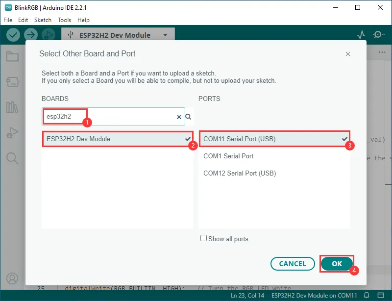
In the Board Manager, select the "ESP32H2 Dev Module" model for development.
-
The ESP32-H2-Zero uses the ESP32-H2 native USB port instead of UART to USB. For serial communication:
-
The
printf()function can be used directly; -
To use the
Serial.println()function, additional configuration is required: Enable the "USB CDC On Boot" option in the IDE's Tools menu, or declare anHWCDCobject in your code to handle USB serial communication.
-
Example
The Arduino examples are located in the Arduino directory of the example package.
| Example | Basic Description | Dependency Library |
|---|---|---|
| 01_BLE | The ESP32 device can be discovered and connected by a Bluetooth debug assistant | - |
| 02_BlinkRGB | RGB LED breathing effect with color cycling | - |
| 03_UART | Serial printing via native USB port; USB CDC On Boot must be enabled | - |
| 04_Zigbee | Zigbee communication test | - |
| 05_GetChipID | Read the chip ID | - |
| 06_lvgl8.4.0_demo | Text display via the 1.83inch LCD Module | lvgl8.4.0 |
| 07_lvgl9.2.2_demo | Text display via the 1.83inch LCD Module | lvgl9.2.2 |
| 08_1.83inch | Connects to the 1.83inch LCD Module for color cycle test, touch function test, and image swipe switching | LovyanGFX 1.2.26 |
01_BLE
This example demonstrates BLE advertising. The ESP32-H2-Zero device can be discovered by a Bluetooth debug assistant. After connection, messages can be sent from the assistant to the board. USB CDC On Boot must be enabled.
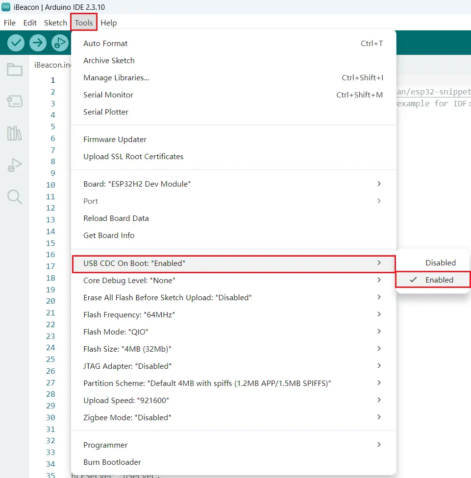
Boards Manager esp32 by Espressif Systems version 3.3.10
Expected Behavior

02_BlinkRGB
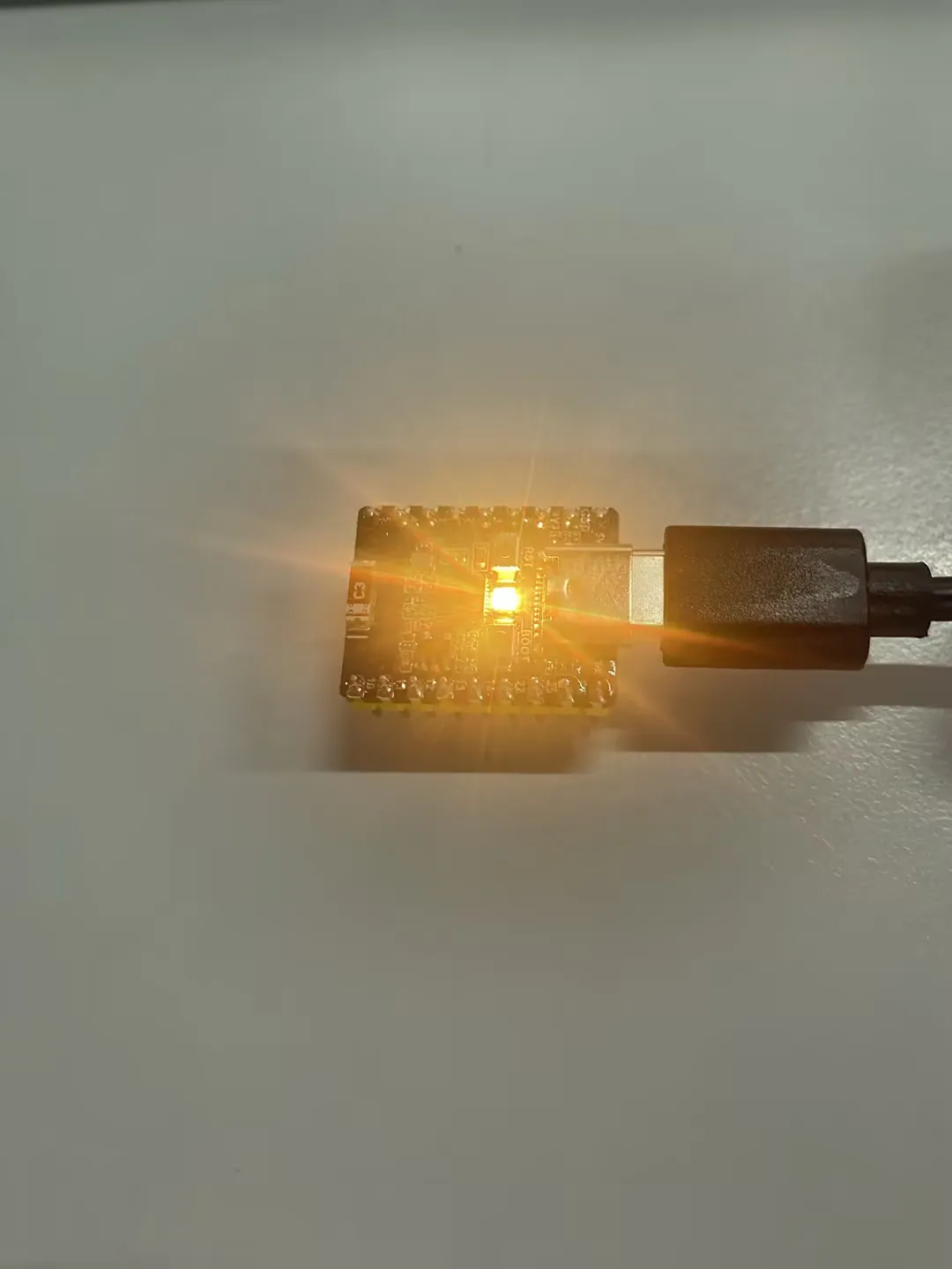
This example demonstrates the onboard RGB LED breathing effect, with the LED blinking and cycling through colors.
Expected Behavior
03_UART
This example outputs serial information via the native USB port. If using Serial.println() for output, "USB CDC On Boot" must be enabled in Arduino IDE.
Expected Behavior

04_Zigbee
This example demonstrates Zigbee communication testing.
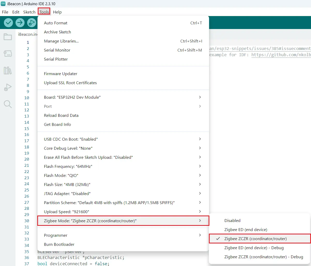
Parameter Configuration
Configure the board to be flashed with the light example as Zigbee ED (End Device).
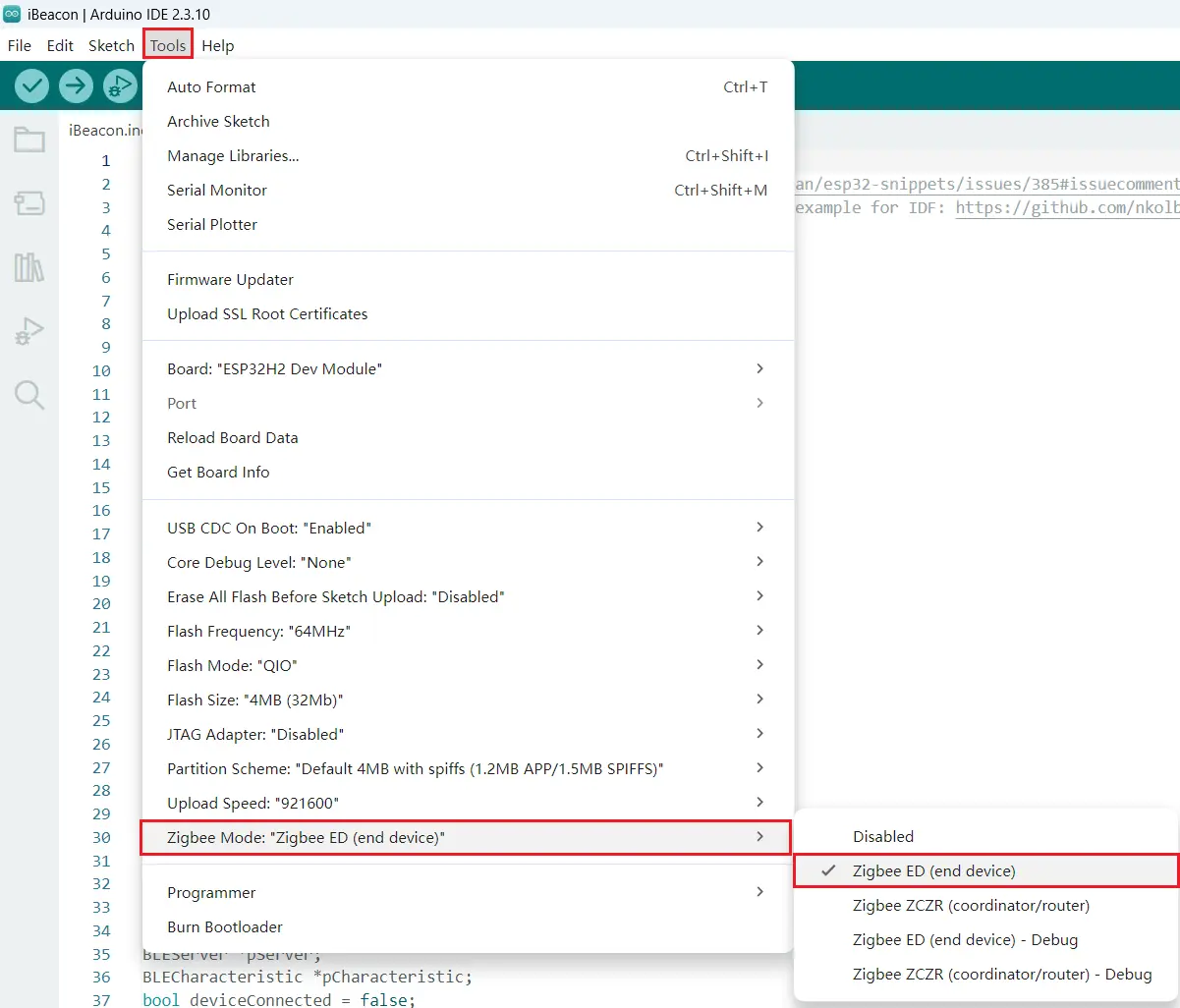
Configure the board to be flashed with the switch example as Zigbee ZCZR (Zigbee Coordinator/Zigbee Router).
Expected Behavior
Pressing the BOOT button on the switch board controls the RGB LED on the light board.
05_GetChipID
This example reads and prints the chip ID.
Expected Behavior

06_lvgl8.4.0_demo
This example uses LVGL 8.4.0, GFX_Library_for_Arduino, and SensorLib for text display. To view serial output, enable "USB CDC On Boot".
Hardware Connection
| 1.83inch Touch LCD Module | ESP32-H2-Zero |
|---|---|
| VCC | 3V3 |
| GND | GND |
| LCD_DIN | GPIO2 |
| LCD_CLK | GPIO1 |
| LCD_CS | GPIO5 |
| LCD_DC | GPIO3 |
| LCD_RST | GPIO4 |
| LCD_BL | GPIO24 |
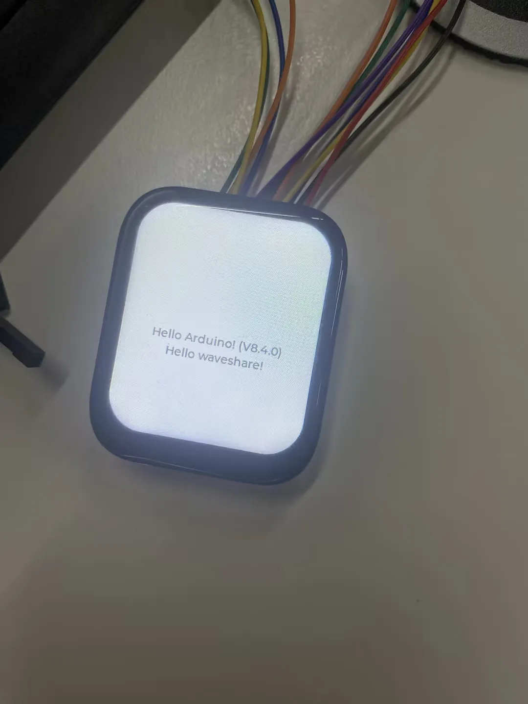
Expected Behavior
The serial monitor baud rate must be 115200 to print the following strings.

07_lvgl9.2.2_demo
This example uses LVGL 9.2.2, GFX_Library_for_Arduino, and SensorLib for text display. To view serial output, enable "USB CDC On Boot".
Hardware Connection
| 1.83inch Touch LCD Module | ESP32-H2-Zero |
|---|---|
| VCC | 3V3 |
| GND | GND |
| LCD_DIN | GPIO2 |
| LCD_CLK | GPIO1 |
| LCD_CS | GPIO5 |
| LCD_DC | GPIO3 |
| LCD_RST | GPIO4 |
| LCD_BL | GPIO24 |
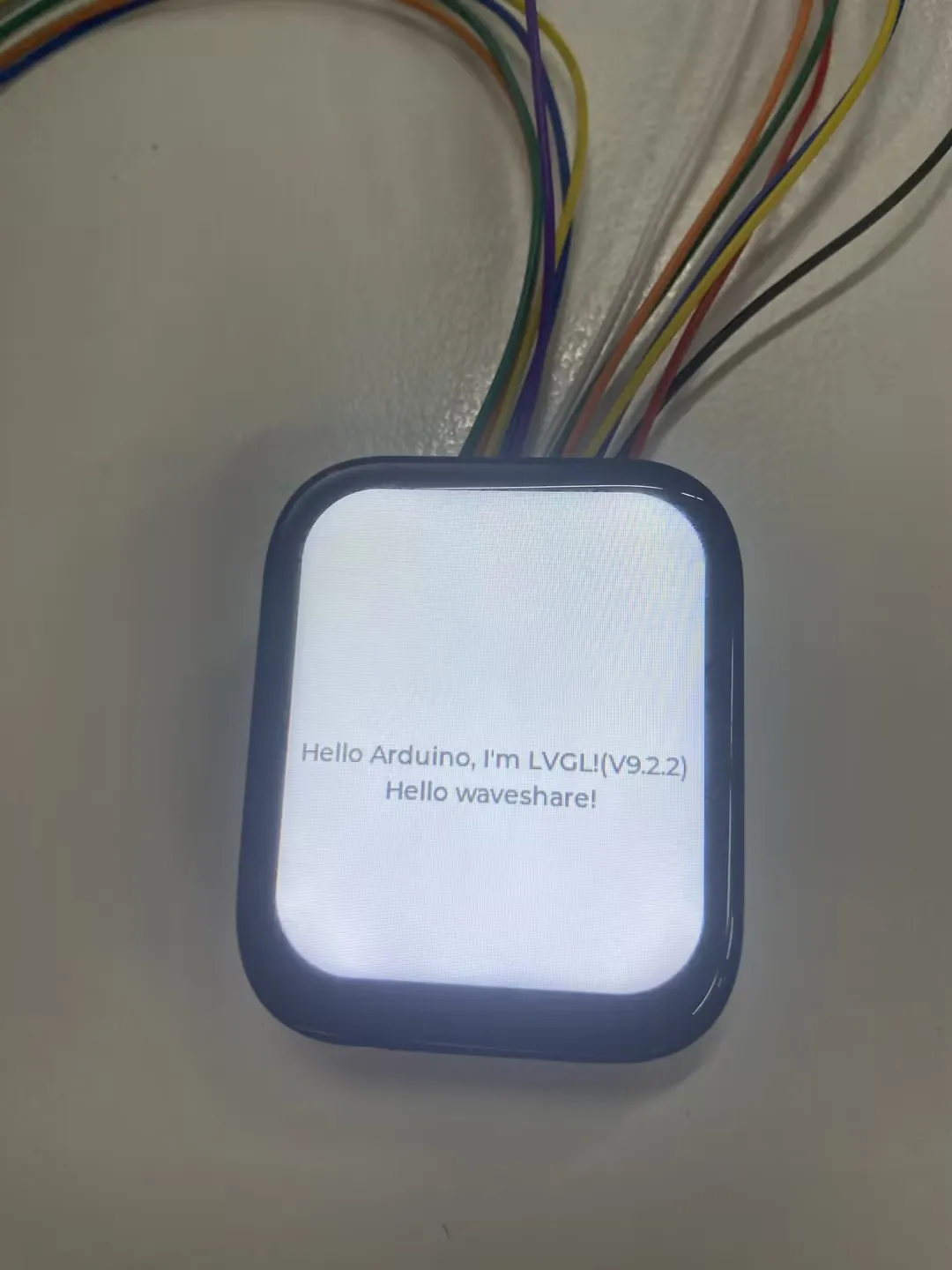
Expected Behavior
The serial monitor baud rate must be 115200 to print the following strings.

08_1.83inch
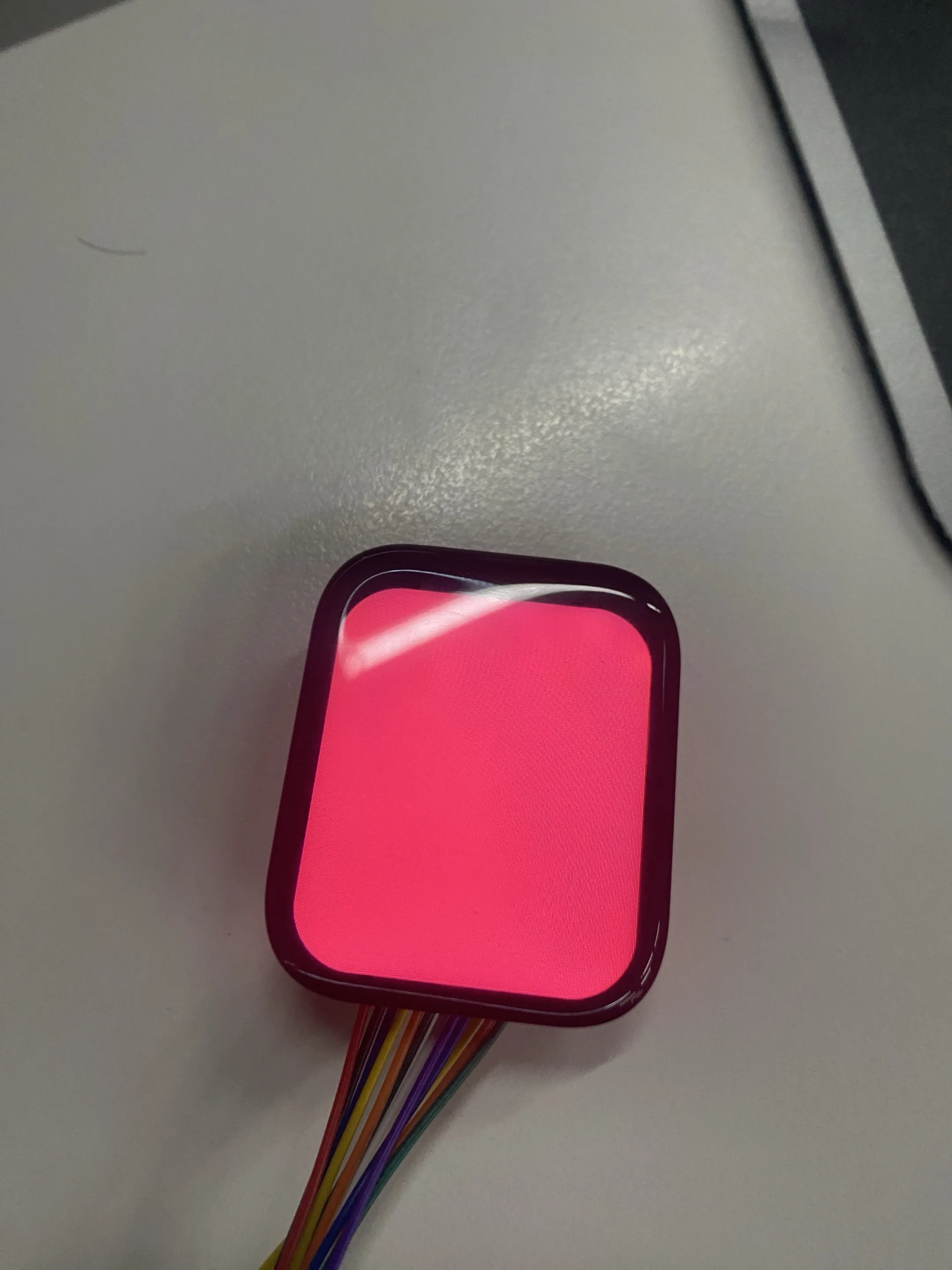
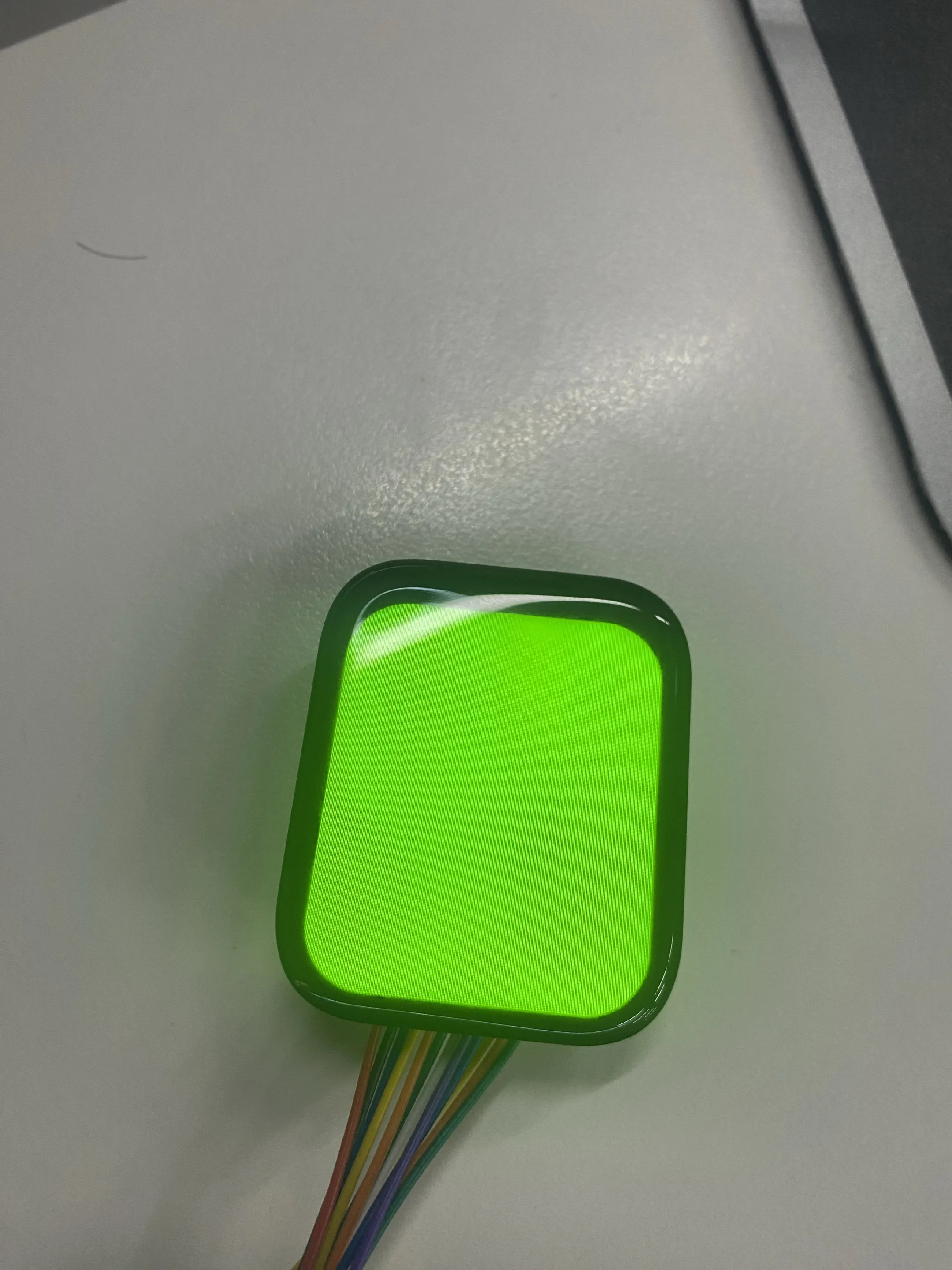
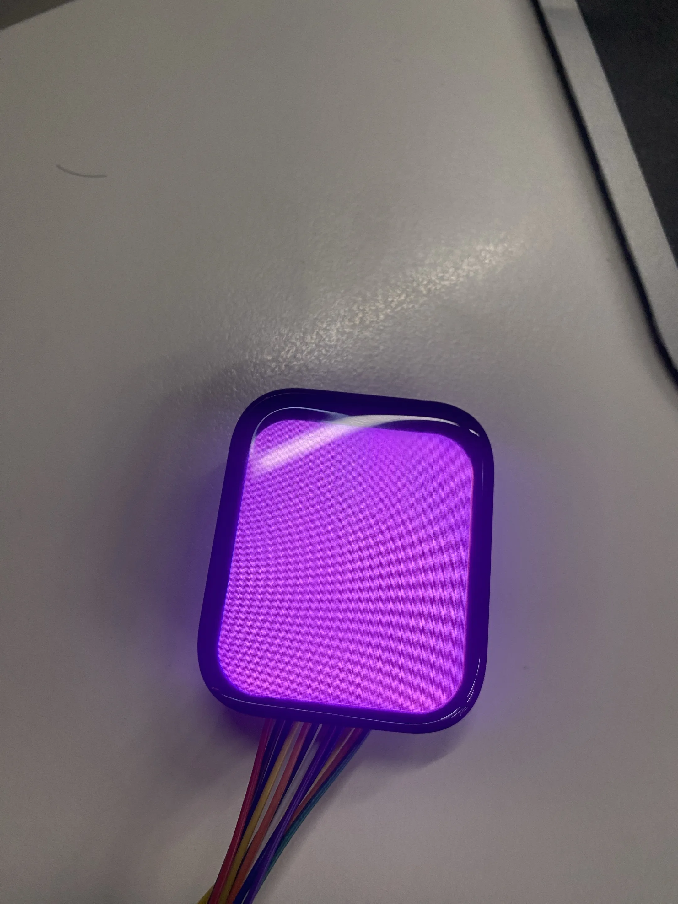
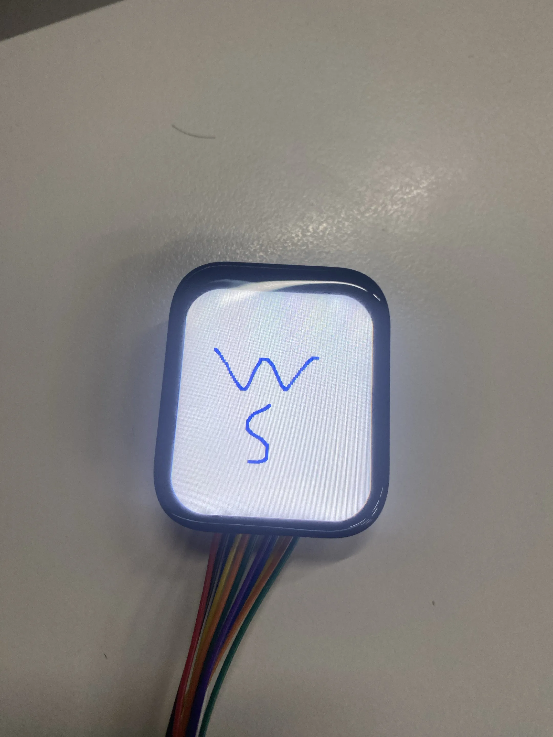
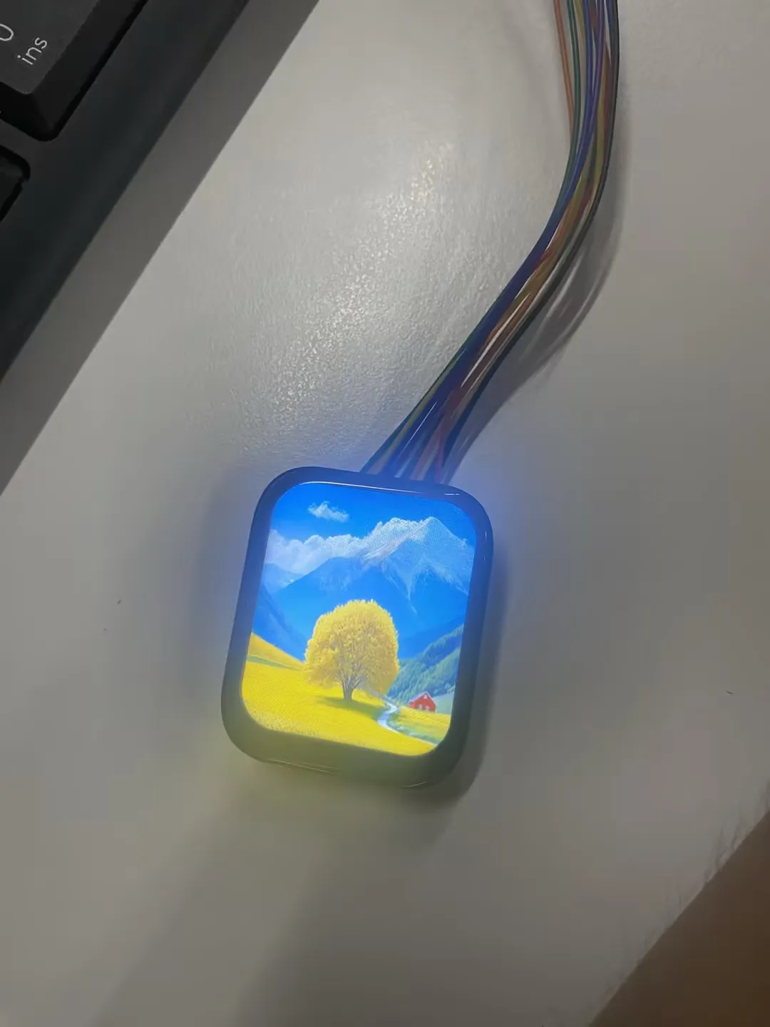
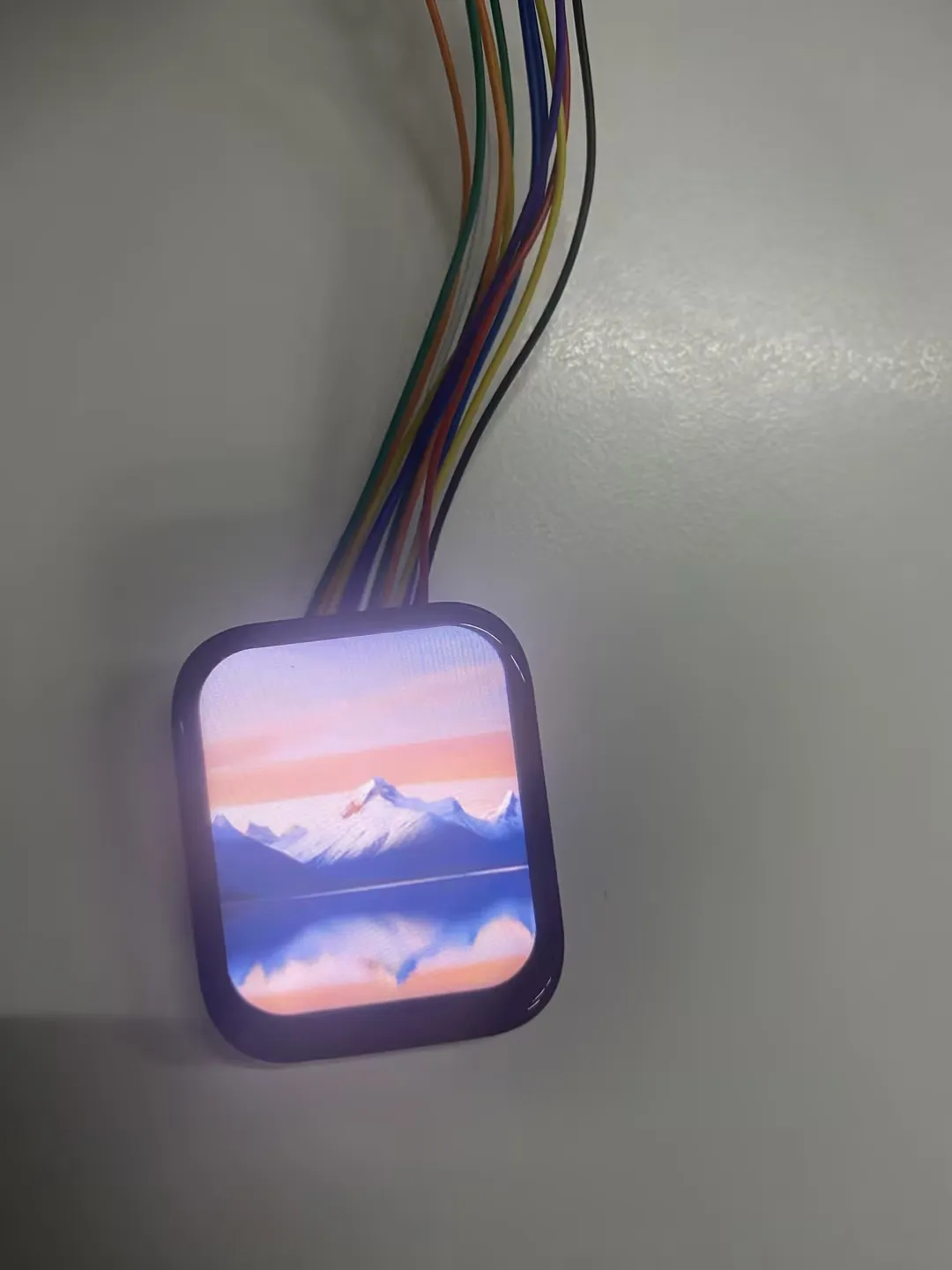
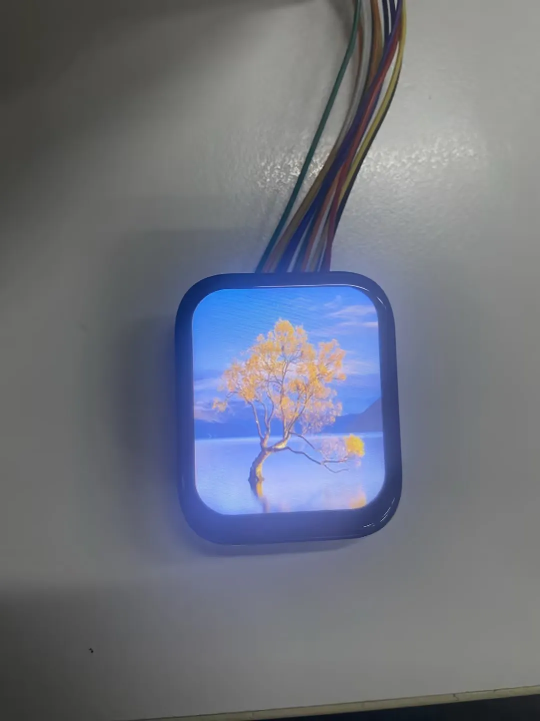
This example demonstrates how to drive the 1.83inch Touch LCD Module based on the ESP32-H2 board and Arduino framework, implementing a color cycle test, CST816S touch function test, and using LovyanGFX to display images directly, with support for left/right swipe gestures for image switching.
Hardware Connection
| 1.83inch Touch LCD Module | ESP32-H2-Zero |
|---|---|
| VCC | 3V3 |
| GND | GND |
| LCD_DIN | GPIO2 |
| LCD_CLK | GPIO1 |
| LCD_CS | GPIO5 |
| LCD_DC | GPIO3 |
| LCD_RST | GPIO4 |
| LCD_BL | GPIO24 |
| TP_SDA | GPIO25 |
| TP_SCL | GPIO22 |
| TP_RST | GPIO10 |
| TP_INT | GPIO11 |
Expected Behavior
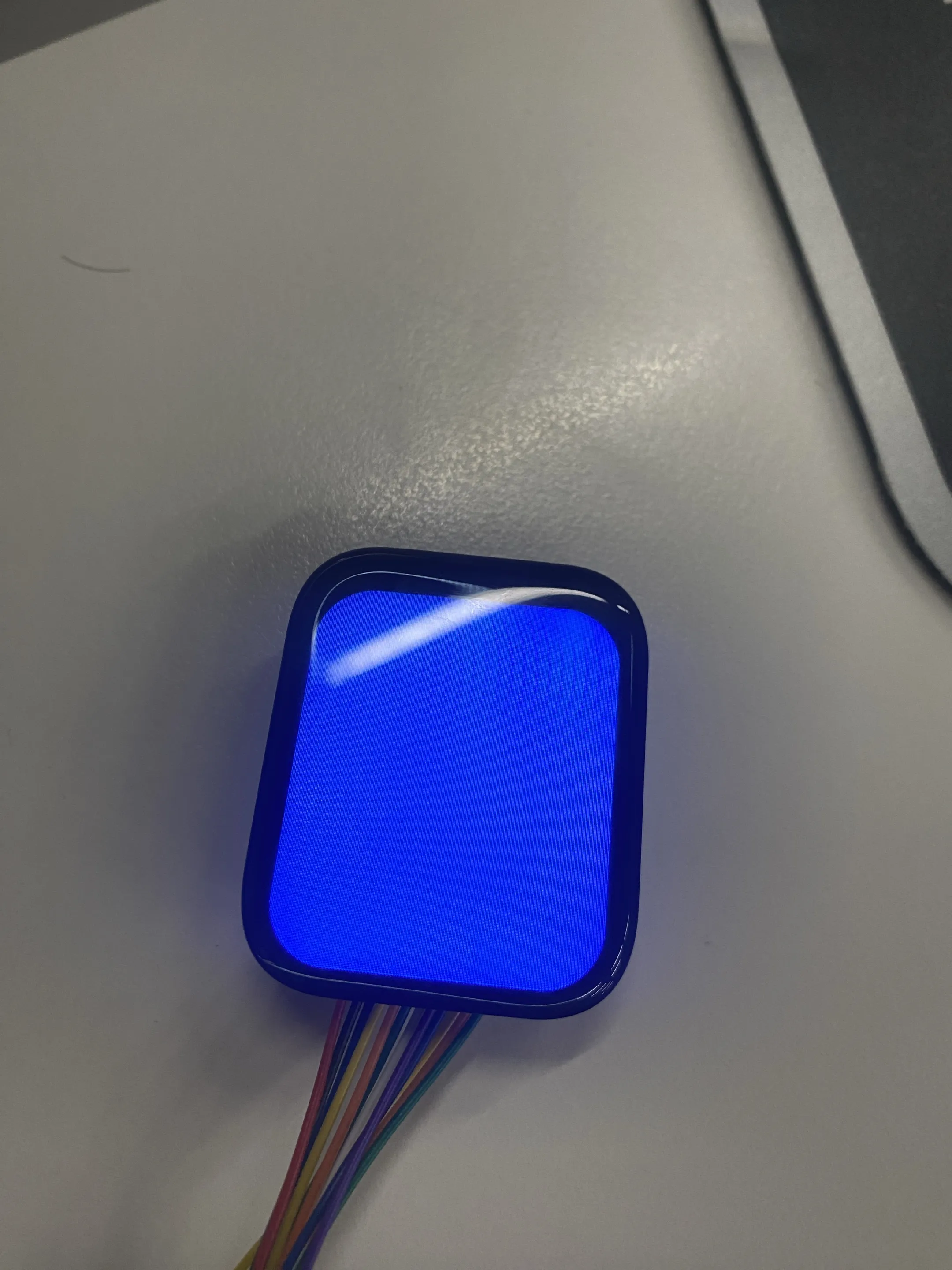
Modify the DEMO_IMAGE_ALBUM macro in the project arduino.ino to switch between two example modes:
-
When
#define DEMO_IMAGE_ALBUM 0:-
LCD Color Cycle Test:
-
LCD Touch Test:
-
-
When
#define DEMO_IMAGE_ALBUM 1:-
LVGL Image Switching Test:
-
Documentation Feedback
If you encounter any issues during use, feel free to leave a comment.