Working with ESP-IDF
This chapter includes the following sections, please read as needed:
- ESP-IDF Getting Started
- Setting Up the Development Environment
- Running Official Espressif Examples
- Example
- Documentation Feedback
ESP-IDF Getting Started
New to ESP32 ESP-IDF development and looking to get started quickly? We have prepared a general Getting Started Tutorial for you.
- Section 1: Environment Setup
- Section 2: Running Examples
- Section 3: Creating a Project
- Section 4: Using Components
- Section 5: Debugging
- Section 6: FreeRTOS
- Section 7: Peripherals
- Section 8: Wi-Fi Programming
- Section 9: BLE Programming
Please Note: This tutorial uses the ESP32-S3-Zero as a teaching example, and all hardware code is based on its pinout. Before you start, it is recommended that you check the pinout of your development board to ensure the pin configuration is correct.
Setting Up the Development Environment
The following tutorial is based on the Windows development environment using VS Code.
ESP-IDF has supported ESP32-H2 since v5.1.
For new development boards using the ESP32-H2 v1.2 chip, please use one of the following versions: ESP-IDF v5.1.6 or later, v5.2.5 or later, v5.3.3 or later, v5.4.1 or later, or v5.5 or later.
Please refer to Waveshare ESP-IDF Getting Started - Section 1 Set Up Environment to complete the ESP-IDF development environment configuration.
Running Official Espressif Examples
Please refer to Waveshare ESP-IDF Getting Started - Section 2 Run Example.
For firmware flashing, Flash erasing, and download mode operations, please refer to Flash Firmware Flashing and Erasing.
Example
The ESP-IDF examples are located in the ESP-IDF directory of the product example package.
| Example | Basic Description |
|---|---|
| 01_Hello_World | Prints Hello World |
| 02_BlinkRGB | RGB LED breathing effect with color cycling |
| 03_GetChipID | Read the chip ID |
| 04_BLE | The ESP32 device can be discovered by a Bluetooth debug assistant, broadcasting data as ESP32-H2 |
| 05_ieee802154_cli | Provides a command line for testing IEEE 802.15.4 |
| 06_Zigbee | Two devices communicate via Zigbee as switch and light |
| 07_UART | Short GPIO23/24 for UART data printing |
| 08_1.83inch | Connects to the 1.83inch LCD Module for color cycle test, touch function test, and LVGL graphic library display |
01_Hello_World
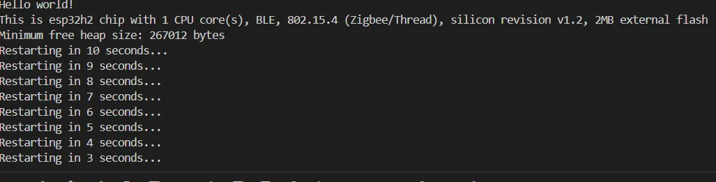
This example demonstrates the basic serial output function of the ESP32-H2-Zero. After startup, it prints "Hello World!" via the serial port every ten seconds.
Hardware Connection
Connect the board to your computer using a USB cable.
Software Operation
- This example is compatible with the ESP32-C6; no modification to the example code is required.
- In the ESP-IDF extension, select the ESP32-H2 target chip and the corresponding serial port, then compile, flash, and open the serial monitor. The serial port number can be found in the Windows Device Manager.
Expected Behavior
02_BlinkRGB
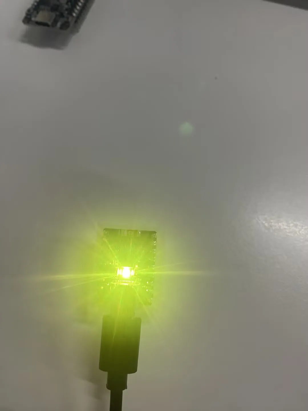
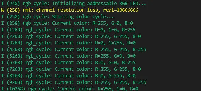
This example demonstrates the onboard RGB LED breathing effect, with the LED blinking and cycling through colors.
Expected Behavior
03_GetChipID
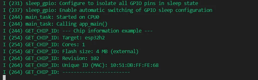
This example obtains and prints hardware information of the ESP32-H2 chip, including the chip model, revision, core count, and chip ID.
Expected Behavior
04_BLE
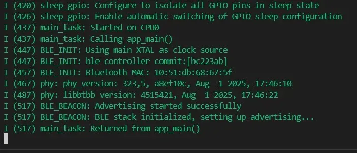
This example sets the board to BLE advertising, broadcasting data as ESP32-H2, and the device can be discovered by a Bluetooth debug assistant.
Parameter Configuration
First, open an ESP-IDF terminal.

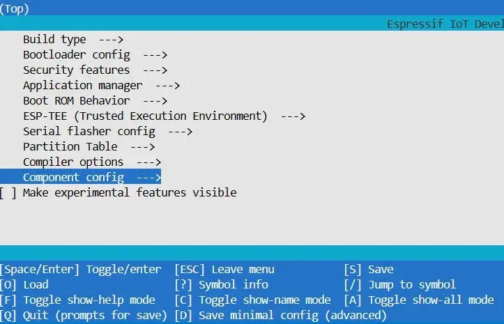
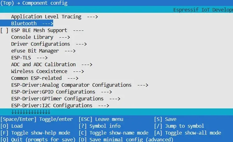
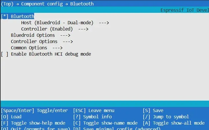
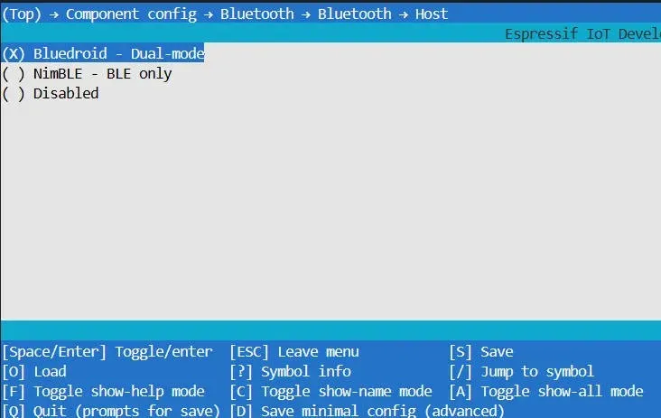
Enter idf.py menuconfig to enter the configuration interface, then follow the highlighted selections in the images:
Navigate to Component config → Bluetooth, enable Bluetooth, and select Bluedroid - Dual-mode under Host for this example.
The Bluedroid - Dual-mode option selects the host stack. On the ESP32-H2, Bluedroid supports Bluetooth LE only; Classic Bluetooth is not supported. This example enables the controller in BLE mode using ESP_BT_MODE_BLE.
Expected Behavior
05_ieee802154_cli
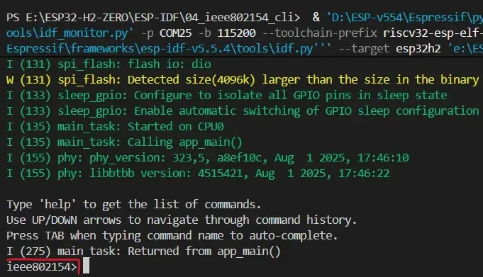
This example provides an IEEE 802.15.4 command line interface. Commands can be entered through the serial terminal for transmission, reception, and parameter testing.
| Command | Function |
|---|---|
channel -g / -s <n> | Get/Set channel number |
rx -r <0|1> | Enable/Disable receive mode |
tx <bytes> / tx -l <len> | Transmit MAC frame |
txpower -g / -s <n> | Get/Set transmit power |
panid <id> / panid -g | Set/Get PAN ID |
shortaddr <addr> / -g | Set/Get short address |
extaddr <addr> / -g | Set/Get extended address |
promisc -e / -d / -g | Enable/Disable/Get promiscuous mode |
coordinator -e / -d / -g | Enable/Disable/Get coordinator mode |
cca -g / -m <mode> / -v <val> | Get/Set CCA mode and threshold |
ed -d <duration> | Energy detection |
pending | Manage pending address table |
reg -r / -w | Read/write registers |
esp154 -e / -d | Initialize/De-initialize 802.15.4 subsystem |
restart | Software reset |
free / heap | View heap memory |
help | View all command help |
Parameter Configuration
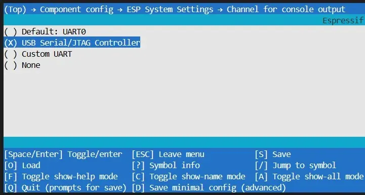
This example uses UART0 as the console output by default, but the board's Type-C port occupies the same port during flashing, causing a conflict. It is recommended to reconfigure the console output channel in the ESP-IDF terminal.
First, open an ESP-IDF terminal.
Enter idf.py menuconfig to enter the configuration interface, then follow the path below:
Component config → ESP System Settings → Channel for console output
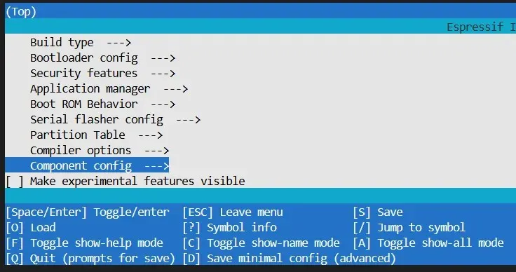
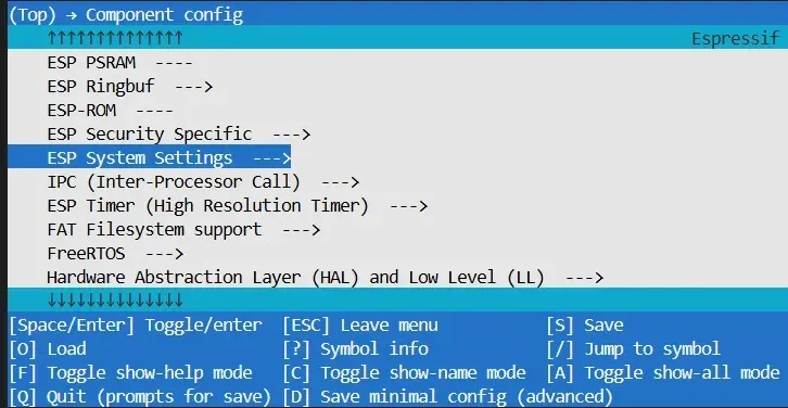
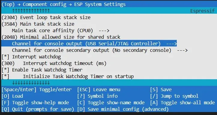
Change the console output channel from UART0 to USB Serial/JTAG Controller.
Expected Behavior
06_Zigbee
This example demonstrates Zigbee communication and requires two devices, one as a switch and one as a light.
This example requires two ESP32-H2 boards. The board flashed with HA_on_off_switch controls the RGB LED on the other board via the BOOT button.
Flash HA_on_off_switch to one board first, then HA_on_off_light to the other.
Parameter Configuration
First, open an ESP-IDF terminal.
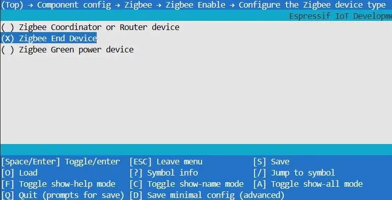
Enter idf.py menuconfig to enter the configuration interface, then follow the highlighted selections in the images:
Component config → Zigbee → Configure the Zigbee device type
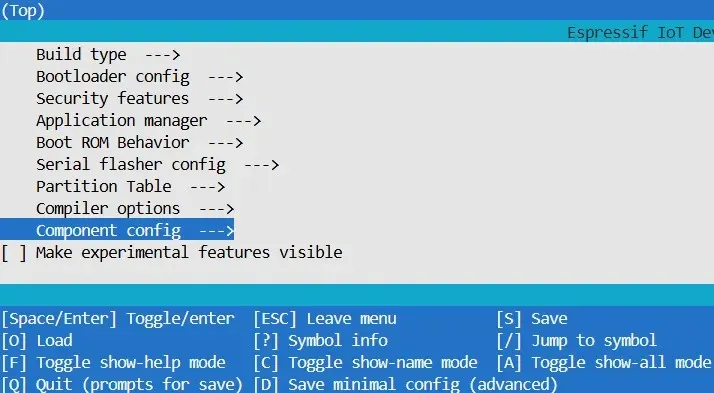
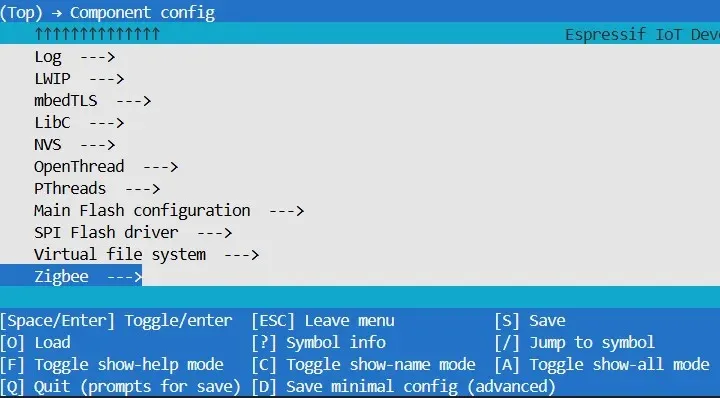
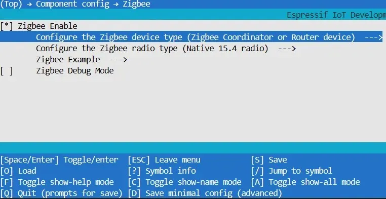
Configure the board to be flashed with the switch example as Zigbee Coordinator or Router device.
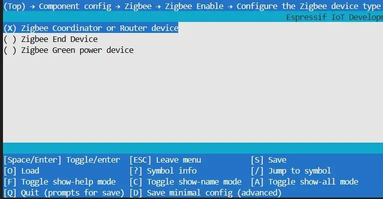
Configure the board to be flashed with the light example as Zigbee End device.
Expected Behavior
Pressing the BOOT button on the board flashed with the switch example controls the RGB LED on the light board.
-
light:

-
switch:

07_UART
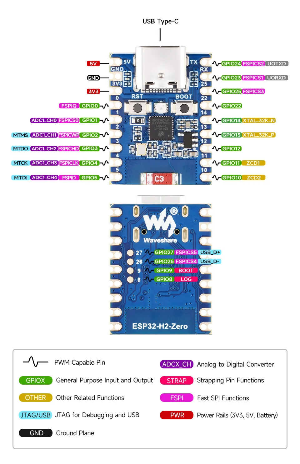
This example demonstrates UART self‑loopback. Use a jumper wire to short GPIO23 and GPIO24, then run the example.
Expected Behavior

08_1.83inch
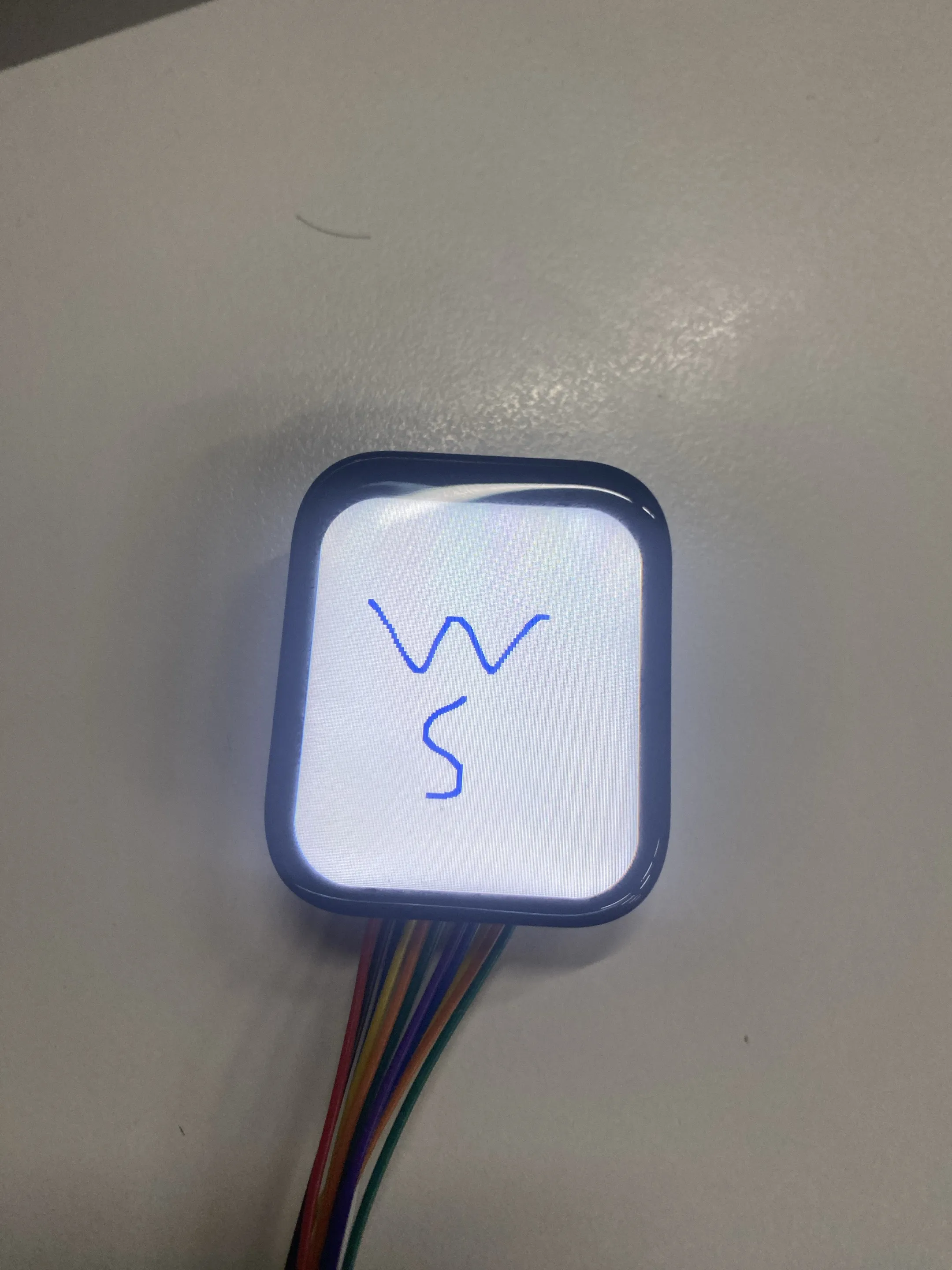
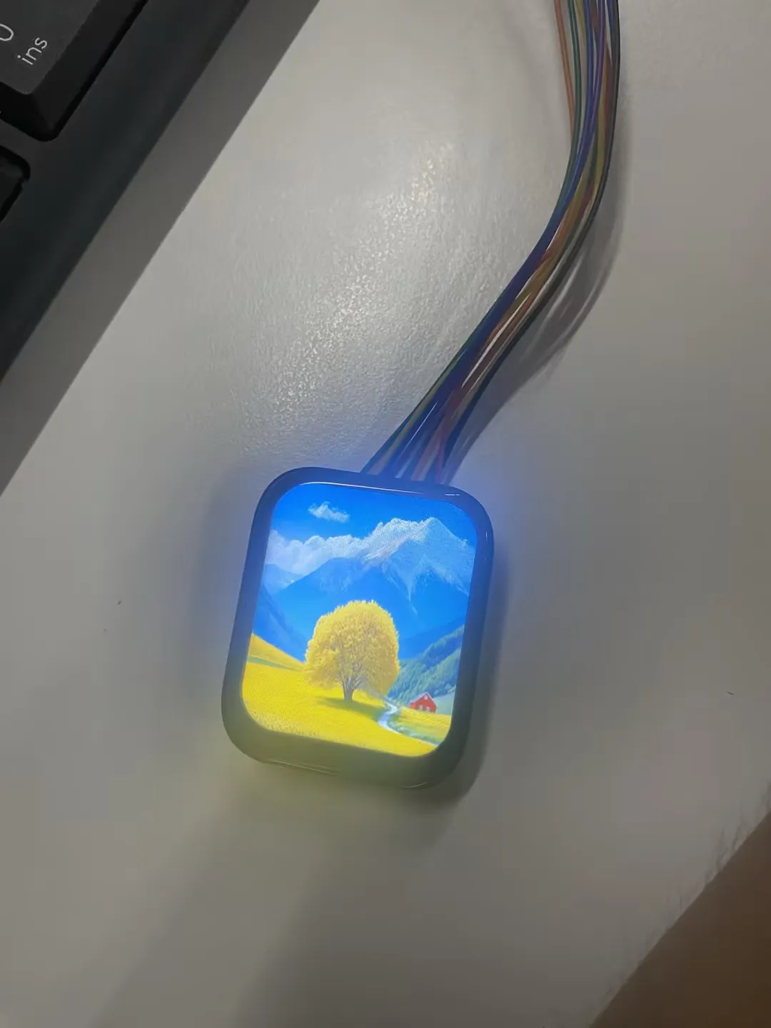
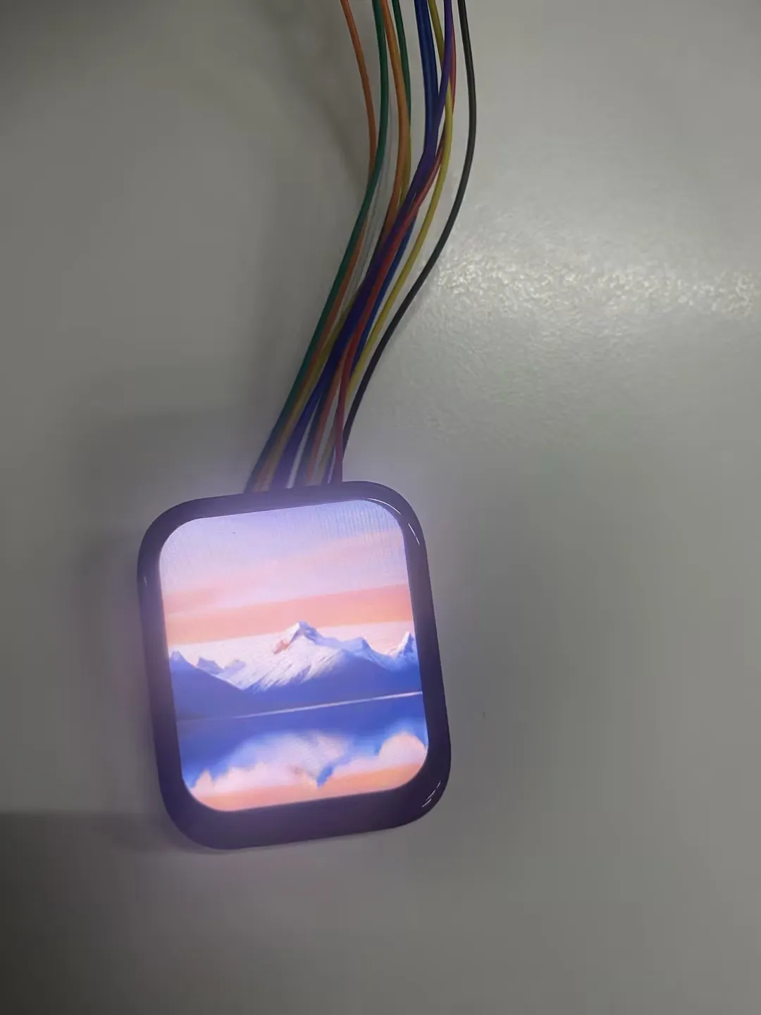
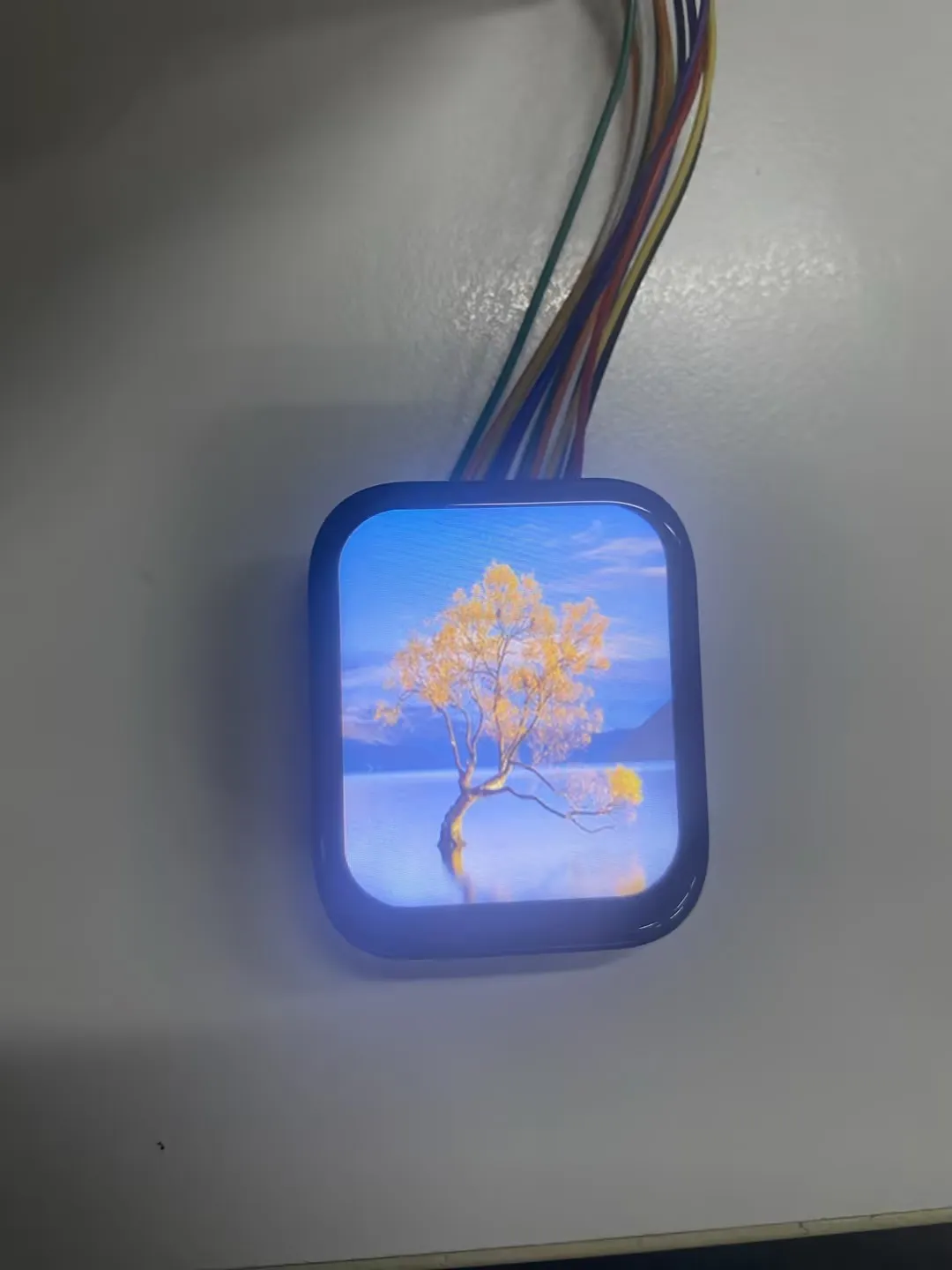
This example demonstrates how to drive the 1.83inch Touch LCD Module based on the ESP32-H2 board, implementing color cycle test and touch function test, while also reserving image display capability based on the LVGL graphics library, with support for left/right swipe gestures for image switching.
Hardware Connection
| 1.83inch Touch LCD Module | ESP32-H2-Zero |
|---|---|
| VCC | 3V3 |
| GND | GND |
| LCD_DIN | GPIO2 |
| LCD_CLK | GPIO1 |
| LCD_CS | GPIO5 |
| LCD_DC | GPIO3 |
| LCD_RST | GPIO4 |
| LCD_BL | GPIO24 |
| TP_SDA | GPIO25 |
| TP_SCL | GPIO22 |
| TP_RST | GPIO10 |
| TP_INT | GPIO11 |
Expected Behavior
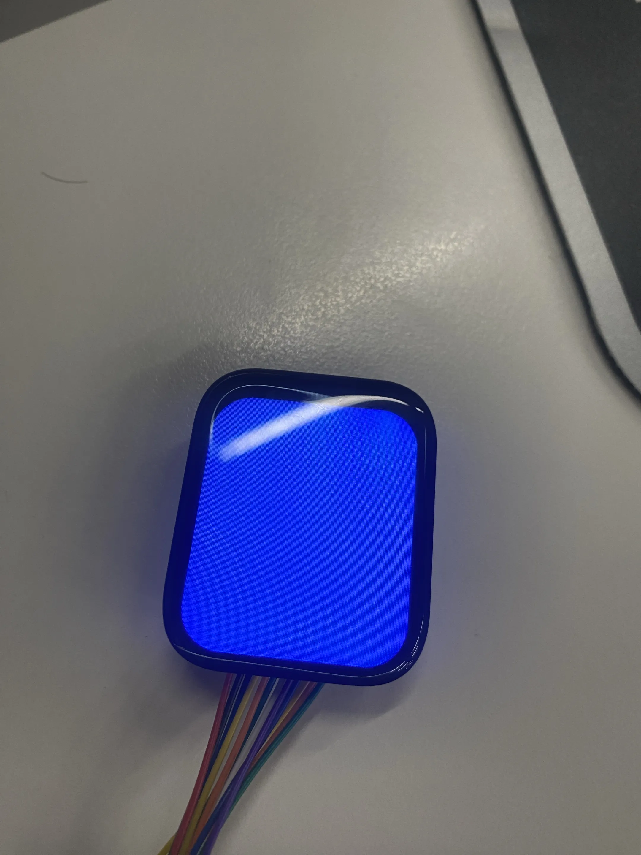
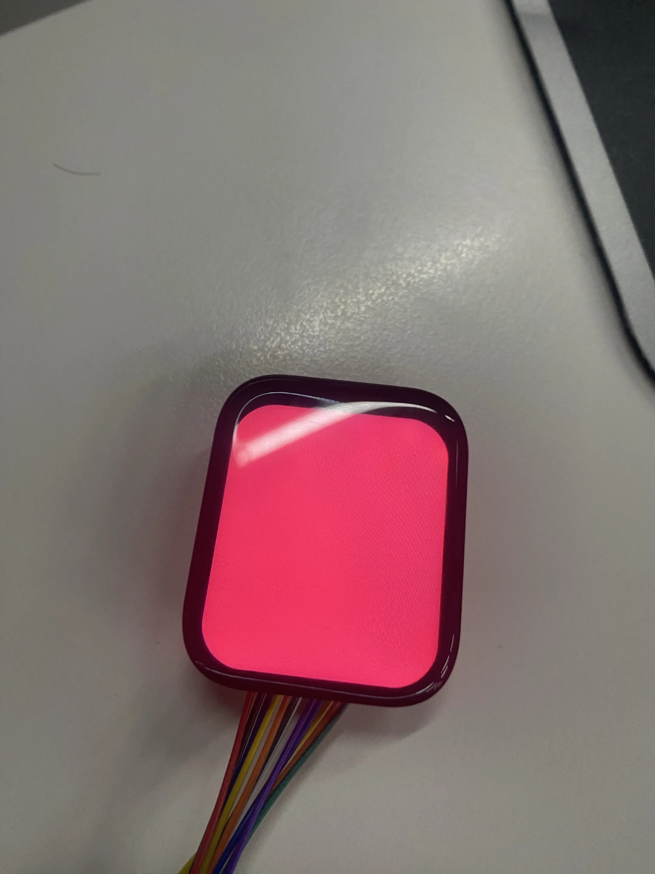
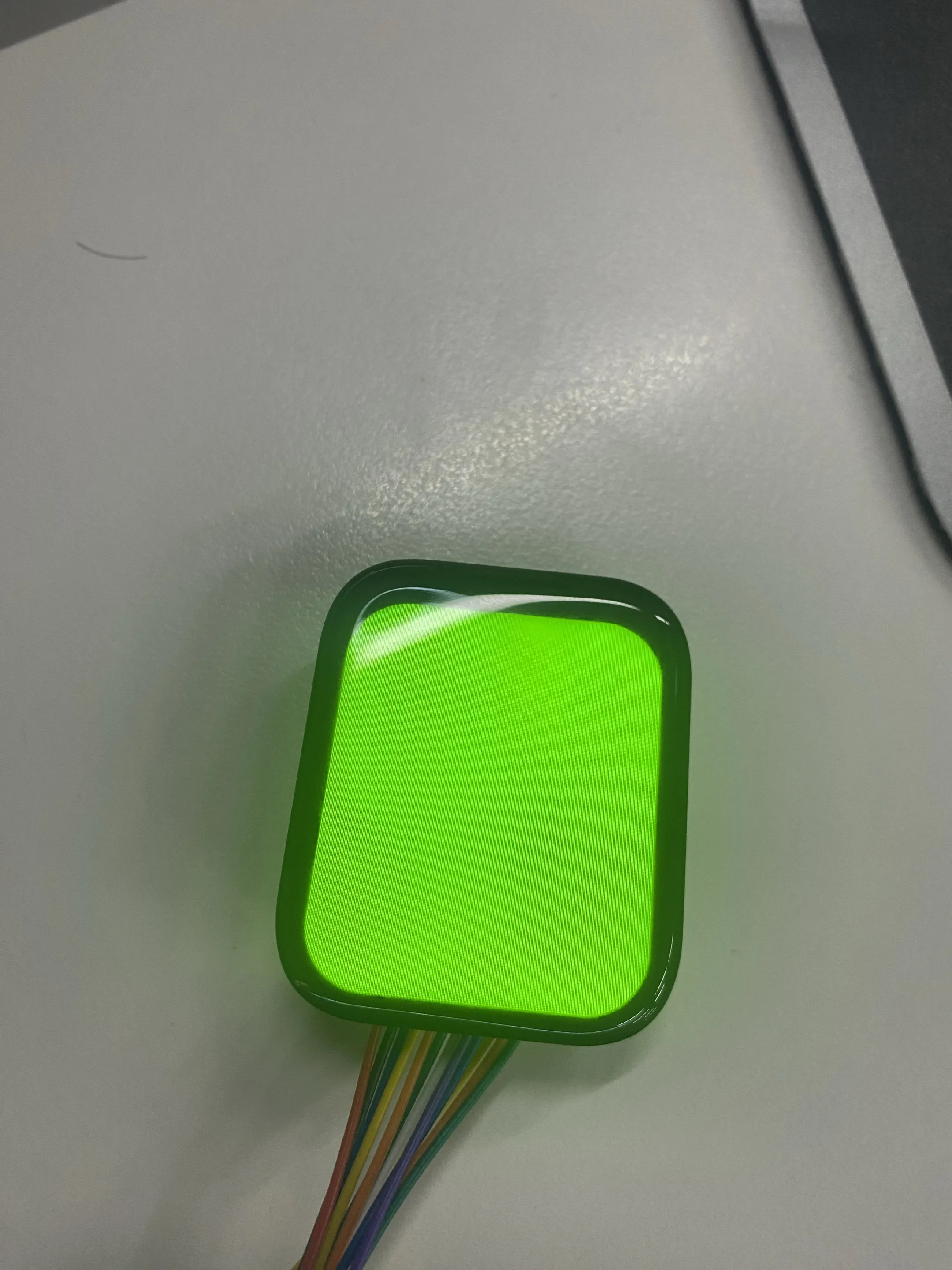
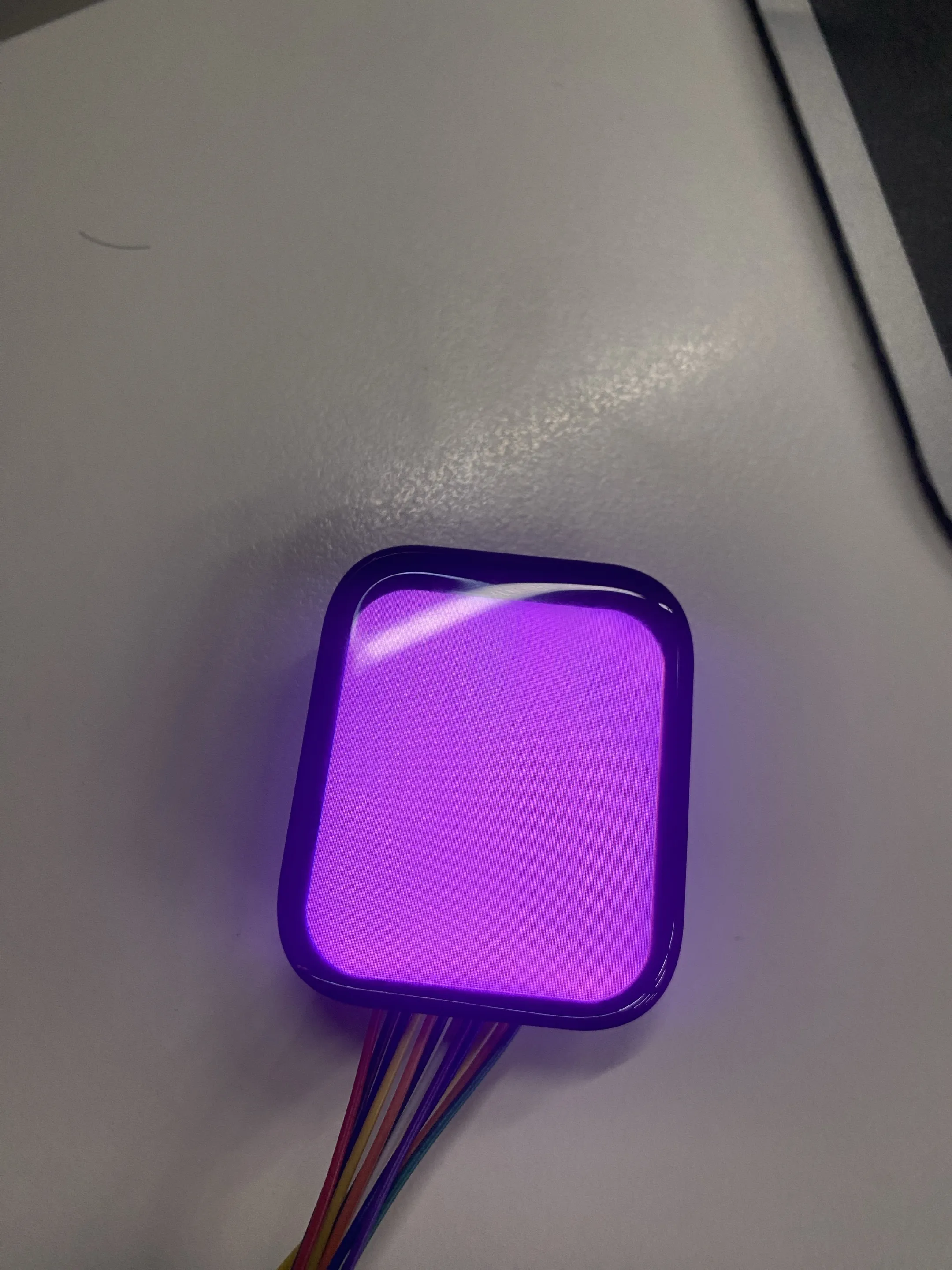
Modify the DEMO_IMAGE_ALBUM macro in the project main.c to switch between two demonstration modes:
-
When
#define DEMO_IMAGE_ALBUM 0:-
LCD Color Cycle Test:
-
LCD Touch Test:
-
-
When
#define DEMO_IMAGE_ALBUM 1:-
LVGL Image Switching Test:
-
Documentation Feedback
If you encounter any issues during use, feel free to leave a comment.