ESP32-P4-Core-DEV-KIT
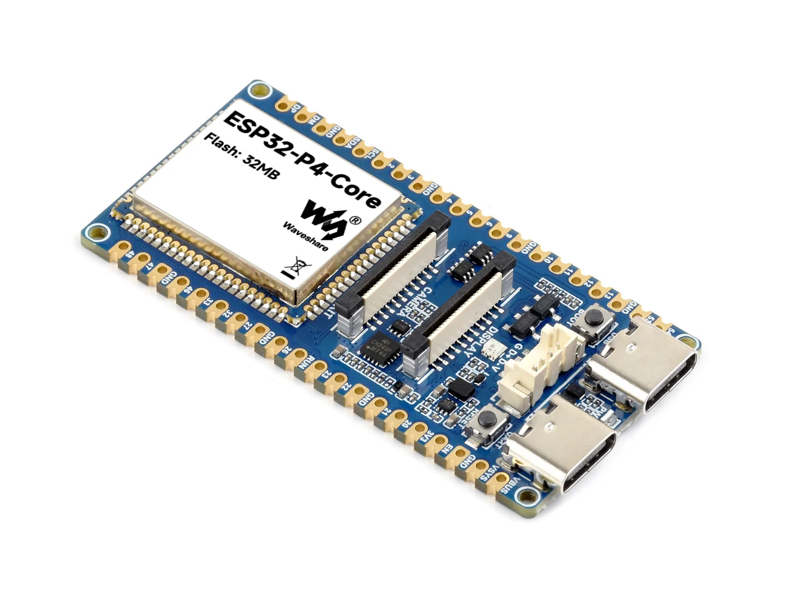
ESP32-P4-Core-DEV-KIT is a compact multimedia development board designed by Waveshare around the ESP32-P4-Core module. It features an ESP32-P4 MCU with 32 MB of onboard NOR Flash and 32 MB of stacked PSRAM inside the ESP32-P4 package, making it well-suited for HMI, edge computing, multimedia capture, visual display, and I/O expansion prototyping.
The board exposes MIPI-CSI, MIPI-DSI, USB OTG 2.0 HS, SPI, I2S, I2C, LED PWM, MCPWM, RMT, ADC, UART, and TWAI interfaces, along with 2×20 pin headers and bottom GPIO pads for connecting displays, cameras, USB peripherals, and custom expansion circuits. This board is included in the support matrix of the ESP32-P4 Platform example repository.
| SKU | Product |
|---|---|
| 34679 | ESP32-P4-Core-DEV-KIT |
| 34680 | ESP32-P4-Core-DEV-KIT-M |
If you are looking for:
- Coding with AI tools: Click Ask AI and select an AI tool to ask questions about this page, or choose Copy page to copy its content and paste it into an AI tool for coding assistance.
- Schematics, datasheets, and example code: See Resources
- ESP-IDF development: See Working with ESP-IDF
- Troubleshooting: See Product FAQ or contact Technical Support
Features
- Processor
- Dual-core RISC-V 32-bit HP system with DSP, instruction-set extensions, and FPU, up to 400 MHz
- Single-core RISC-V 32-bit LP system, up to 40 MHz
- Memory
- 128 KB HP ROM, 16 KB LP ROM, 768 KB HP L2MEM, 32 KB LP SRAM, and 8 KB TCM
- 32 MB PSRAM stacked inside ESP32-P4 package; 32 MB NOR Flash integrated on the ESP32-P4-Core module
- Peripheral Interfaces
- Onboard MIPI-CSI camera interface and MIPI-DSI display interface for image capture, screen output, and HMI
- USB OTG 2.0 HS for extending USB devices or validating high-speed USB applications
- SPI, I2S, I2C, LED PWM, MCPWM, RMT, ADC, UART, TWAI for connecting sensors, audio, control, and communication peripherals
- 2×20 pin headers and bottom GPIO pads; available with or without pre-soldered headers
- Security
- Secure boot, flash encryption, hardware crypto accelerators, and hardware random number generator
- Hardware access protection for access control and privilege separation
Hardware Description
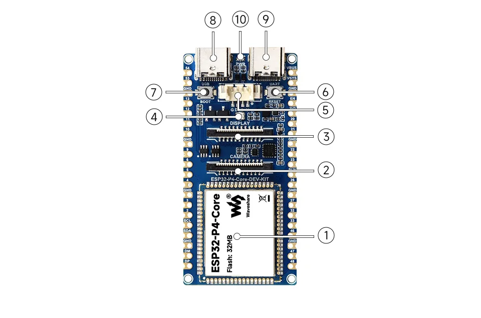
- ESP32-P4-Core integrates the ESP32-P4 and 32 MB NOR Flash; the ESP32-P4 package stacks 32 MB PSRAM
- Camera Interface 2-lane MIPI-CSI, 22-pin, 0.5 mm pitch
- Display Interface 2-lane MIPI-DSI, 22-pin, 0.5 mm pitch
- WS2812B RGB LED
- MX1.25 4PIN Connector Uses an MX1.25 4Pin connector to expose the ESP32-P4's USB 2.0 High-Speed OTG signals, which can be used to connect USB peripherals or configure the development board as a USB device
- RST Button resets the board
- BOOT Button press during power-on or reset to enter download mode
- Type-C Interface for power and program flashing
- Type-C UART Interface for power, program flashing, and serial debugging
- Power Indicator LED
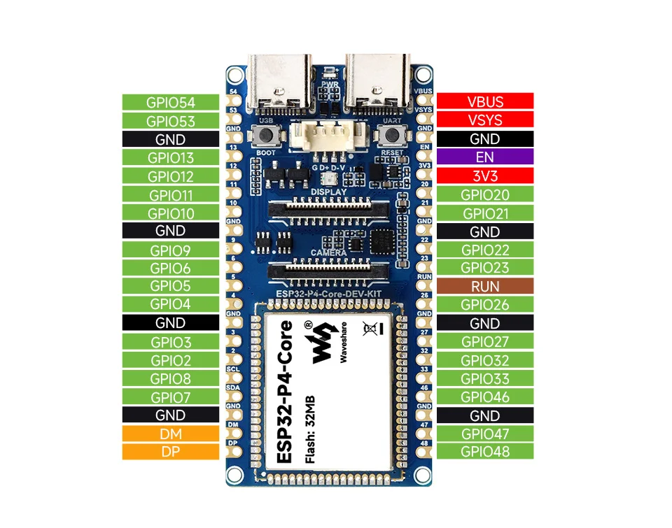
Pinout Definition
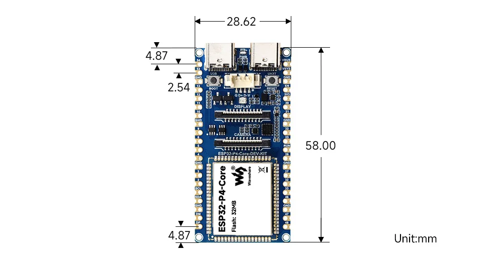
Dimensions
Development Tools
The ESP32-P4-Core-DEV-KIT is supported for development with ESP-IDF. Arduino support for the ESP32-P4 is still maturing; the current documentation focuses on the ESP-IDF workflow and examples.
Arduino platform support for the ESP32-P4 remains limited at this stage. We recommend using ESP-IDF for development. For Arduino-related discussions, see Support of Arduino.
ESP-IDF, short for Espressif IoT Development Framework, is the development framework provided by Espressif for the ESP series chips. It supports C and C++ development and includes the build system, debugger, flashing tool, and serial monitor. You can use it from the command line or pair it with Visual Studio Code and the Espressif IDF extension. For environment setup, see the Working with ESP-IDF (VS Code) guide, which also includes example program documentation.