ESP32-P4-Knob-Touch-AMOLED-1.75
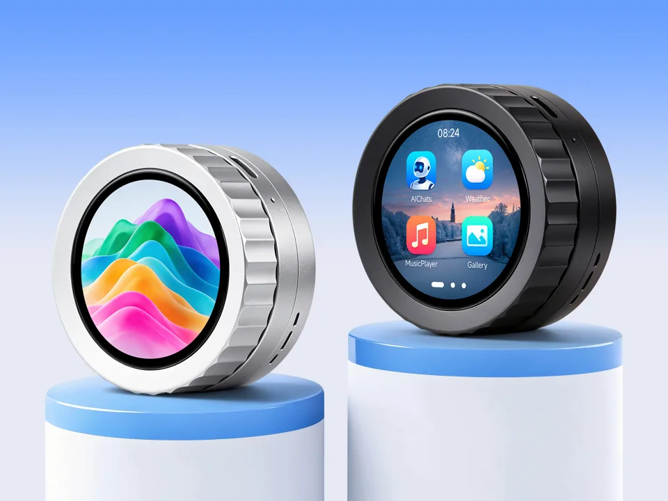
The ESP32-P4-Knob-Touch-AMOLED-1.75 is a knob display development board based on the ESP32-P4NRW32X. It combines a 1.75inch 466 × 466 capacitive touch AMOLED display, an ESP32 wireless coprocessor, a rotary knob with vibration feedback, a power management IC, a six-axis IMU, an RTC, an audio codec with dual microphones, and a TF card slot in a CNC-machined metal case. The factory firmware is built on ESP-Brookesia and provides media playback, Bluetooth audio, a USB extended display for Windows, a voice assistant, and other applications. ESP-IDF and Arduino examples are provided for secondary development.
If you are looking for:
- Coding with AI tools: Click Ask AI and select an AI tool to ask questions about this page, or choose Copy page to copy its content and paste it into an AI tool for coding assistance.
- Example code, firmware, and datasheets: See Resources
- Factory firmware: See Factory Firmware Usage
- Arduino development: See Working with Arduino
- ESP-IDF development: See Working with ESP-IDF
- Troubleshooting: See FAQ or contact Technical Support
Version Options
The four versions differ in case color and in whether a lithium battery is installed.
| Model | Case Color | Lithium Battery | Package Contents |
|---|---|---|---|
| ESP32-P4-Knob-Touch-AMOLED-1.75S | Silver | 3.7V 800mAh 102035 lithium battery, installed before shipment | Host ×1 |
| ESP32-P4-Knob-Touch-AMOLED-1.75S-EN | Silver | Not included | Host ×1, anti-slip rubber ring ×1 |
| ESP32-P4-Knob-Touch-AMOLED-1.75B | Black | 3.7V 800mAh 102035 lithium battery, installed before shipment | Host ×1 |
| ESP32-P4-Knob-Touch-AMOLED-1.75B-EN | Black | Not included | Host ×1, anti-slip rubber ring ×1 |
A 1GB TF card is installed in the TF card slot of every version.

ESP32-P4-Knob-Touch-AMOLED-1.75S

ESP32-P4-Knob-Touch-AMOLED-1.75S-EN

ESP32-P4-Knob-Touch-AMOLED-1.75B

ESP32-P4-Knob-Touch-AMOLED-1.75B-EN
Features
- Uses the ESP32-P4NRW32X with RISC-V 32-bit dual-core and single-core processors, 128KB HP ROM, 16KB LP ROM, 768KB HP L2MEM, 32KB LP SRAM, and 8KB TCM
- 32MB PSRAM in the chip package and 32MB NOR Flash on the board
- Onboard ESP32-D0WD-V3 wireless coprocessor for 2.4GHz Wi-Fi (802.11 b/g/n), Classic Bluetooth, and BLE 4.2, with an onboard ceramic antenna and an IPEX 1 connector
- Image and voice processing peripherals, including a JPEG codec, Pixel Processing Accelerator (PPA), Image Signal Processor (ISP), and H.264 encoder
- 1.75inch 466 × 466 AMOLED display with a MIPI-DSI interface and capacitive touch
- Rotary knob with two direction switches, and a vibration motor for haptic feedback
- ES8389 audio codec, ES7210 audio ADC, dual microphones with an echo cancellation circuit, a speaker amplifier, a speaker installed in the case, and a 3.5mm audio jack
- AXP2101 power management IC, PCF85063 RTC, QMI8658 six-axis IMU, and a TF card slot with a 1GB TF card installed
- USB Type-C port: the plug orientation selects either the ESP32-P4 USB 2.0 port or the USB-to-UART serial port
- Security features: Secure Boot, Flash Encryption, cryptographic accelerators, TRNG, Digital Signature Peripheral, and Key Management Unit; hardware access protection supports Access Permission Management and Privilege Separation
- CNC-machined metal case in silver or black
AMOLED Specifications
| Parameter | Value | Parameter | Value |
|---|---|---|---|
| Display panel | AMOLED | Display size | 1.75inch |
| Resolution | 466 × 466 pixels | Display colors | 16.7M |
| Brightness | 700 cd/m² | Contrast ratio | 100000:1 |
| Interface | MIPI-DSI | Display driver IC | CO5300 |
| Touch | Capacitive | Touch IC | CST9217 |
Onboard Resources
Main Board
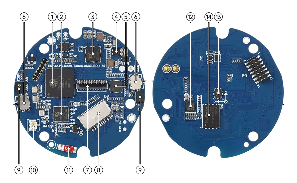
- ESP32-P4NRW32X: main controller with 32MB PSRAM in the package
- ESP32-D0WD-V3: wireless coprocessor for Wi-Fi and Bluetooth, 240MHz operating frequency, with 2MB Flash
- AXP2101: power management IC
- PCF85063: RTC chip
- ES7210: audio ADC, supports echo cancellation algorithms for audio capture
- Knob direction switches: two switches triggered by knob rotation, one for each direction
- Display connector: connects the 1.75inch AMOLED panel
- TF card slot: a 1GB TF card is installed by default
- Dual microphones: with an echo cancellation circuit
- IPEX 1 connector: for an external antenna; switch to it by resoldering an onboard resistor
- Onboard ceramic antenna: for 2.4GHz Wi-Fi (802.11 b/g/n) and Bluetooth
- ES8389: audio codec
- QMI8658: six-axis IMU with a 3-axis gyroscope and a 3-axis accelerometer
- 32MB NOR Flash
Adapter Board
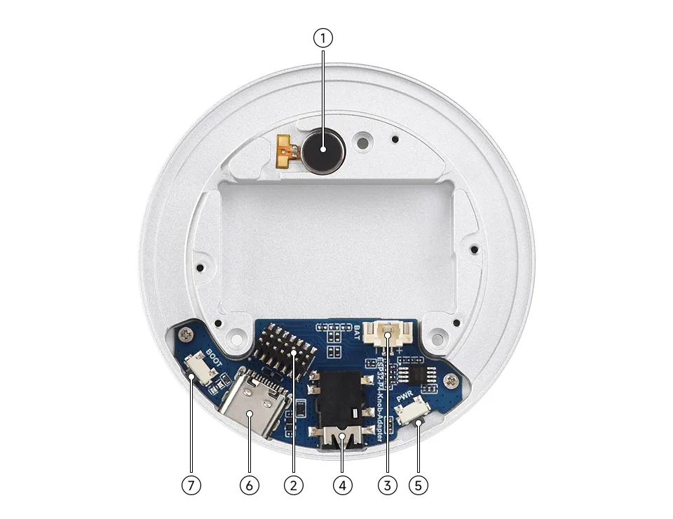
- Vibration motor
- PH1.27 14PIN SMD header
- PH1.25 lithium battery header: for a 3.7V lithium battery
- 3.5mm audio jack
- PWR button
- USB Type-C port: the plug orientation selects the ESP32-P4 USB 2.0 port or the USB-to-UART serial port
- BOOT button: hold BOOT and power on the board again to enter download mode
One orientation of the USB Type-C plug connects the onboard CH343P USB-to-UART chip, which is connected to ESP32-P4 UART0 (GPIO37 TXD, GPIO38 RXD) and is used for flashing and serial logs. The other orientation connects the ESP32-P4 high-speed USB 2.0 port, which is used by USB Screen, the USB drive function in Settings, and the USB display example. Flipping the plug powers the board up again.
Internal Hardware Connections
The following connections are taken from the board definition used by the examples. The onboard I2C devices share one bus.
Display and Touch: CO5300 AMOLED and CST9217 touch (click to expand)
| ESP32-P4 | Signal | Description |
|---|---|---|
| MIPI-DSI | DSI, 1 data lane | CO5300 display data |
| GPIO29 | LCD_RST | Display reset, active low |
| LDO_VO3 | VDD_MIPI_DPHY | MIPI D-PHY supply, 2.5V |
| GPIO7 | TP_SDA | Touch I2C data |
| GPIO8 | TP_SCL | Touch I2C clock |
| GPIO26 | TP_INT | Touch interrupt, active low |
| GPIO27 | TP_RST | Touch reset, active low |
I2C Bus: onboard I2C devices and addresses (click to expand)
The I2C bus uses GPIO7 (SDA) and GPIO8 (SCL). The addresses below are 7-bit addresses.
| Device | Function | I2C Address |
|---|---|---|
| CST9217 | Capacitive touch | 0x5A |
| ES8389 | Audio codec | 0x10 |
| ES7210 | Audio ADC | 0x40 |
| AXP2101 | Power management | 0x34 |
| PCF85063 | RTC | 0x51 |
| QMI8658 | Six-axis IMU | 0x6B; the examples also probe 0x6A |
Audio: ES8389, ES7210, and NS4150B amplifier (click to expand)
| ESP32-P4 | Signal | Description |
|---|---|---|
| GPIO13 | I2S_MCLK | I2S master clock |
| GPIO12 | I2S_BCLK | I2S bit clock |
| GPIO10 | I2S_WS | I2S word select |
| GPIO9 | I2S_DOUT | Playback data to the ES8389 |
| GPIO11 | I2S_DIN | Microphone data from the ES7210 |
| GPIO53 | PA_EN | NS4150B speaker amplifier enable on the adapter board, active high |
The two microphones are connected to ES7210 MIC1 and MIC2.
Knob and Vibration Motor (click to expand)
| ESP32-P4 | Signal | Description |
|---|---|---|
| GPIO20 | KNOB_CW | Clockwise direction switch, active low, one pulse per detent |
| GPIO21 | KNOB_CCW | Counterclockwise direction switch, active low, one pulse per detent |
| GPIO22 | MOTOR_IN1 | DRV8837 IN1 |
| GPIO23 | MOTOR_IN2 | DRV8837 IN2 |
The knob uses two independent direction switches, not a quadrature encoder. Driving IN1 high and IN2 low runs the vibration motor; driving both low stops it.
Buttons and Interrupts (click to expand)
| ESP32-P4 | Signal | Description |
|---|---|---|
| GPIO35 | BOOT | BOOT button, active low |
| GPIO2 | PWR | PWR button state through a BSS138 inverter: HIGH when pressed, LOW when released |
| GPIO3 | RTC_INT | PCF85063 interrupt |
| GPIO4 | IMU_INT1 | QMI8658 INT1 |
| GPIO5 | IMU_INT2 | QMI8658 INT2 |
The PWR button is also connected to the PWRON pin of the AXP2101.
TF Card: SDMMC slot 0 (click to expand)
| ESP32-P4 | Signal | Description |
|---|---|---|
| GPIO43 | SD_CLK | SDMMC clock |
| GPIO44 | SD_CMD | SDMMC command |
| GPIO39 | SD_D0 | SDMMC data 0 |
| GPIO40 | SD_D1 | SDMMC data 1 |
| GPIO41 | SD_D2 | SDMMC data 2 |
| GPIO42 | SD_D3 | SDMMC data 3 |
Dimensions
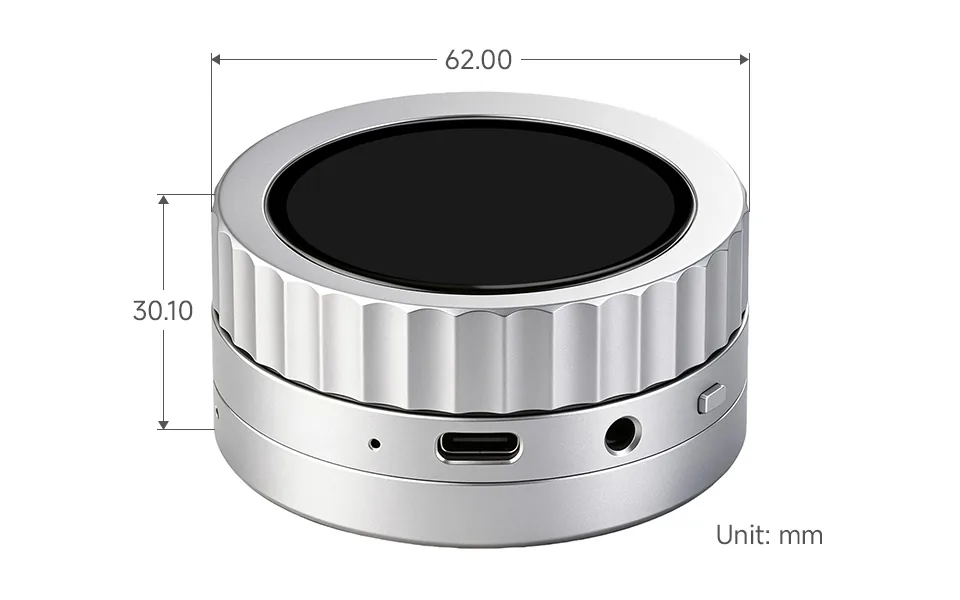
Development Methods
The ESP32-P4-Knob-Touch-AMOLED-1.75 supports both the Arduino IDE and ESP-IDF. The ESP-IDF examples and the factory application use ESP-IDF v6.1; the Arduino examples use Arduino-ESP32 3.3.12.
- Arduino IDE is suitable for quickly running the peripheral examples. The repository provides the board configuration, display, audio, and wireless libraries required by the sketches.
- ESP-IDF is the Espressif IoT Development Framework. It provides project configuration, component management, and debugging tools, and is used to build the factory application.