Working with ESP-IDF
This section describes how to build, flash, and run the ESP-IDF examples. Prepare the board and a USB Type-C cable that supports data transfer, and download the ESP32-P4-Knob-Touch-AMOLED-1.75 Examples.
This chapter includes the following sections. Please read as needed:
- ESP-IDF Getting Started
- Set Up the Development Environment
- Build and Flash
- Example Programs
- Troubleshooting
ESP-IDF Getting Started
New to ESP32 ESP-IDF development and looking to get started quickly? We have prepared a general Getting Started Tutorial for you.
- Section 1: Environment Setup
- Section 2: Running Examples
- Section 3: Creating a Project
- Section 4: Using Components
- Section 5: Debugging
- Section 6: FreeRTOS
- Section 7: Peripherals
- Section 8: Wi-Fi Programming
- Section 9: BLE Programming
Please Note: This tutorial uses the ESP32-S3-Zero as a teaching example, and all hardware code is based on its pinout. Before you start, it is recommended that you check the pinout of your development board to ensure the pin configuration is correct.
Set Up the ESP-IDF Development Environment
Refer to Install ESP-IDF Development Environment to install the environment.
The examples and the factory application use ESP-IDF v6.1. The repository contains 16 basic examples in examples/esp-idf and the factory application in examples/factory. Select ESP-IDF v6.1 when installing the environment.
The following guide uses Windows as an example, demonstrating development using VS Code + the ESP-IDF extension. macOS and Linux users should refer to the official documentation.
The screenshots in this section use ESP-IDF V5.5.2 as an example. When installing, please select the ESP-IDF version that matches your board's example.
Install the ESP-IDF Development Environment
-
Download the installation manager from the ESP-IDF Installation Manager page. This is Espressif's latest cross-platform installer. The following steps demonstrate how to use its offline installation feature.
Click the Offline Installer tab on the page, then select Windows as the operating system and the ESP-IDF version you need (the version shown in the screenshot is for reference only — choose the version that fits your actual needs).
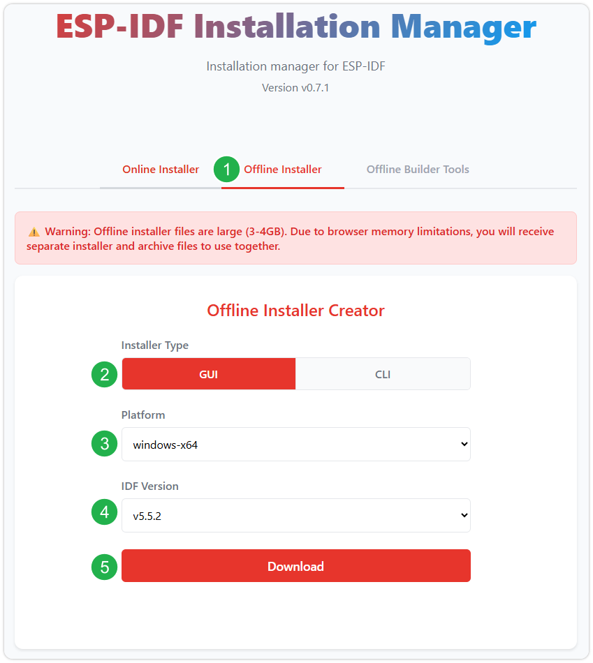
After confirming your selection, click the download button. The browser will automatically download two files: the ESP-IDF Offline Package (.zst) and the ESP-IDF Installer (.exe).
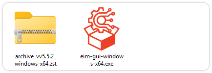
Please wait for both files to finish downloading.
-
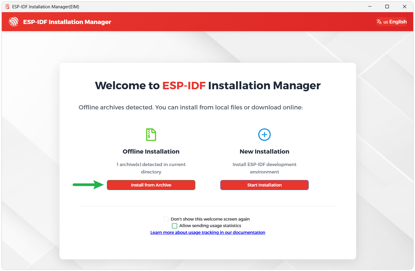
Once the download is complete, double-click to run the ESP-IDF Installer (eim-gui-windows-x64.exe).
The installer will automatically detect if the offline package exists in the same directory. Click Install from archive.
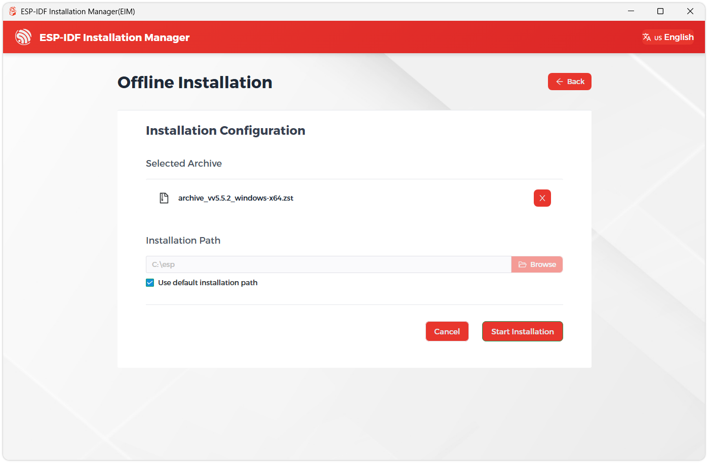
Next, select the installation path. We recommend using the default path. If you need to customize it, ensure the path does not contain Chinese characters or spaces. Click Start installation to proceed.
-
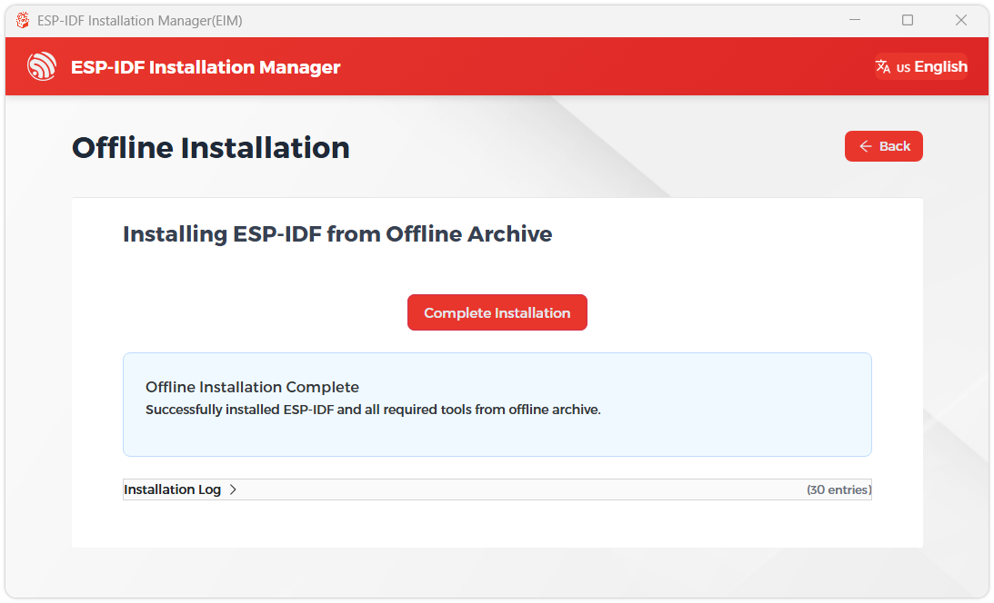
When you see the following screen, the ESP-IDF installation is successful.
-
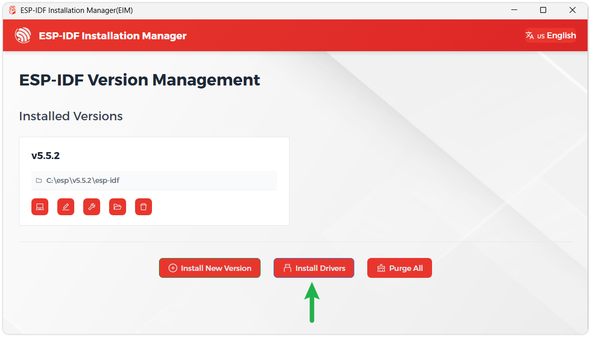
We recommend installing the drivers as well. Click Finish installation, then select Install driver.
Install Visual Studio Code and the ESP-IDF Extension
-
Download and install Visual Studio Code.
-
During installation, it is recommended to check Add "Open with Code" action to Windows Explorer file context menu to facilitate opening project folders quickly.
-
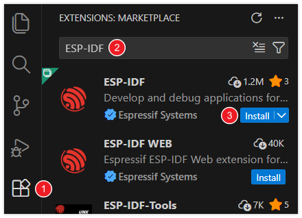
In VS Code, click the Extensions icon
 in the Activity Bar on the side (or use the shortcut Ctrl + Shift + X) to open the Extensions view.
-
Enter ESP-IDF in the search box, locate the ESP-IDF extension, and click Install.
-
For ESP-IDF extension versions ≥ 2.0, the extension will automatically detect and recognize the ESP-IDF environment installed in the previous steps, requiring no manual configuration.
| Environment or Component | Version or Configuration | Description |
|---|---|---|
| ESP-IDF | v6.1 | Use the version required by the examples |
| Target chip | esp32p4 | Set with idf.py set-target esp32p4 |
| Board definition | waveshare/waveshare_boards, board esp32_p4_knob_touch_amoled_1_75 | Downloaded by the ESP-IDF Component Manager; provides the display, touch, audio, TF card, and GPIO configuration |
| Shared board code | examples/esp-idf/common | Board initialization (knob_board) and wireless coprocessor initialization (knob_wireless) shared by the basic examples |
| LVGL | 9.x | Managed by the dependency configuration of each project |
| Serial baud rate | 115200 for the basic examples; 2000000 for the factory application | Used by the serial monitor |
The required components are downloaded according to each project's dependency configuration on the first build. Keep the original configuration files and dependency lock files.
Build and Flash
-
In VS Code, select the installed ESP-IDF v6.1 environment.
-
Open the folder of a single example, for example
examples/esp-idf/11_display_touch. The folder should containCMakeLists.txt. -
Connect the board through the USB-to-UART plug orientation. If no serial port appears, flip the USB Type-C plug at the board end.
-
Open the ESP-IDF terminal in the example folder and run the following command, replacing
COM5with the actual serial port:idf.py set-target esp32p4idf.py -p COM5 build flash monitor -
Check the results as described in Example Programs. Press
Ctrl+]to exit the serial monitor.
The basic examples include examples/esp-idf/common/knob_board/project.cmake through a relative path. Build them inside the repository, or copy the common folder together with the example and keep the same relative location.
CMake generates the Board Manager tables in each build directory. If esp-bmgr-assist is installed, set the environment variable ESP_BOARD_MANAGER_SKIP_GEN_CHECK=1 before building so that its source-directory precheck does not reject these tables.
If flashing cannot connect, close other programs that use the serial port and try again. If the problem persists, hold BOOT, power on the board again, and then release BOOT to enter download mode.
Build the Factory Application
The factory application in examples/factory is a standalone ESP-IDF project. Build and flash it with the same commands in that folder. Its serial log uses 2000000 baud.
The repository does not contain the music files built into the released factory firmware. To include music in a local build, place your own or licensed MP3 files in examples/factory/spiffs/music before building. Keep the spiffs folder because the factory application mounts it at startup.
Example Programs
The examples are located in examples/esp-idf. Each example is an independent project; open its folder and run it as described in Build and Flash.
| Example | Function | View Results |
|---|---|---|
| 01_system_info | Flash, PSRAM, and internal heap information | Serial port |
| 02_buttons | BOOT and PWR button press and release events | Serial port |
| 03_wifi | Wi-Fi access point scan | Serial port |
| 04_bluetooth | BLE GAP scan and summary | Serial port |
| 05_axp2101 | Read-only AXP2101 power status | Screen |
| 06_sd_card | TF card mount and temporary-file verification | Screen, serial port |
| 07_limit_switches | Knob direction switch levels and counts | Screen, serial port |
| 08_motor_drive | Touch-controlled vibration with automatic stop | Screen, vibration motor |
| 09_rtc | PCF85063 RTC time display | Screen |
| 10_qmi8658 | QMI8658 acceleration chart | Screen |
| 11_display_touch | Display color test and touch drawing | Screen |
| 12_mic_spectrum | Microphone FFT spectrum | Screen |
| 13_speaker_output | Speaker test tone | Speaker, serial port |
| 14_usb_display | USB display and HID touch for Windows | Screen, computer |
| 15_lvgl_demo_v9 | LVGL benchmark | Screen |
| 16_a2dp_sink | Bluetooth A2DP audio receiver and display | Screen, speaker |
01_system_info
Reads the ESP32-P4 Flash, PSRAM, and internal heap capacity. The example does not initialize the display or external peripherals.
Expected result: the serial monitor reports the Flash, PSRAM, and internal heap values, then prints PASS when all required values are available. If PSRAM is enabled but fails to initialize, the example reports FAIL.
02_buttons
Reads the BOOT (GPIO35) and PWR (GPIO2) buttons as independent inputs and reports debounced level changes. The example only reads the inputs.
Expected result: each press and release of either button prints a message with the GPIO level. BOOT reads LOW when pressed. PWR reads HIGH when pressed, because GPIO2 is driven through an onboard BSS138 inverter.
03_wifi
Initializes the ESP32 wireless coprocessor and scans nearby Wi-Fi access points. The example does not require credentials and does not connect to a network.
Expected result: the serial monitor prints one scan summary and up to ten access points ordered by signal strength. A result with no visible access points is also valid.
04_bluetooth
Initializes the ESP32 wireless coprocessor and performs Bluetooth Low Energy GAP scanning. The example does not connect, pair, or discover services.
Expected result: at the end of each scan window, the serial monitor prints a summary and up to ten advertisers sorted by RSSI. If a scan cannot start, the error is logged and another scan attempt is scheduled.
05_axp2101
Displays the AXP2101 power management status on an LVGL page. The example does not change power, charging, or regulator settings.
Expected result: the screen shows the AXP2101 online state and the available power, battery, temperature, and charging information. Unavailable readings are shown as N/A. If an I2C or PMU read fails, the error is shown on the screen and in the serial monitor, and the example retries.
06_sd_card
Mounts the TF card in 4-bit SDMMC mode, writes a temporary file, reads it back for verification, deletes the file, and unmounts the card.
Expected result: the screen and the serial monitor show the card information and a successful write, read, and delete round trip, followed by a passed status after the card is unmounted. Mount or verification failures are reported on the screen and in the serial monitor.
07_limit_switches
Monitors the clockwise and counterclockwise direction switches of the knob and shows their levels and trigger counts on an LVGL page.
Expected result: turning the knob updates the HIGH or LOW state and the count of the corresponding direction on the screen and in the serial monitor.
The default mode uses GPIO interrupts and counts a falling edge only after the input has stayed low for 2 ms. Polling, input-only, and PCNT modes can be selected in menuconfig for diagnosis; they count pulses differently.
08_motor_drive
Drives the vibration motor with a press-and-hold button on the screen. Both control lines return to the idle state on release, timeout, or error.
Expected result: the screen shows a VIBRATE button and the motor state. Holding the button starts a short vibration; releasing it or reaching the guard timeout stops the motor and returns the state to IDLE.
The maximum on-time is set by CONFIG_MOTOR08_MAX_ON_MS (400 ms by default); the source code limits it to 500 ms. If GPIO or timer control fails, the screen shows FAULT and the example tries to stop the motor.
09_rtc
Reads the PCF85063 once per second and shows the time and status on the screen. The example validates the BCD time data and does not write a time to the RTC.
Expected result: when the RTC is available, the screen updates the date and time every second. Invalid oscillator or BCD data and I2C read failures clear the clock and show an error.
10_qmi8658
Samples the QMI8658 accelerometer and plots the X, Y, and Z acceleration on the screen. The example probes the addresses 0x6B and 0x6A, verifies that WHO_AM_I is 0x05, and shows the active address and interrupt levels.
Expected result: the chart and the numeric X, Y, and Z values change when the board is moved. If probing, configuration, or reading fails, the screen shows an error and the example configures the device again.
11_display_touch
Checks the display and touch with red, green, and blue full-screen stages, followed by a touch drawing page.
Expected result: touch the screen or press BOOT to move to the next color. After the blue stage, a white drawing page opens; touching it draws black dots, and Clear removes the dots and resets the count.
12_mic_spectrum
Captures audio from the ES7210 microphones and shows a real-time FFT spectrum, RMS level, and peak level on the screen. The playback codec stays disabled.
Expected result: the spectrum bars respond to nearby sound, and the screen shows the RMS, peak, overrun, and read-error values. If audio initialization or sampling fails, the status line shows the failed stage.
13_speaker_output
Initializes the ES8389 playback path and plays a short, low-volume 440 Hz tone every two seconds.
Expected result: the serial monitor reports each playback cycle, and the speaker plays a short tone followed by a quiet interval.
14_usb_display
Exposes the board as a 466 × 466 JPEG USB display for the Espressif USB display driver for Windows, and sends touch input to the computer as a HID touch screen.
Operation: install the Espressif USB Display Driver for Windows on a Windows 10 or Windows 11 computer. After flashing, connect the board in the USB 2.0 plug orientation instead of the USB-to-UART orientation. If the computer does not detect the display, flip the plug and connect again.
Expected result: the log reports that the display is ready at 466 × 466 and reports USB enumeration after the computer configures it. The board shows the frames sent by the computer and sends touch reports back.
15_lvgl_demo_v9
Runs the LVGL benchmark demo on the AMOLED display with touch input.
Expected result: the screen starts the LVGL benchmark after boot.
16_a2dp_sink
Initializes the wireless coprocessor, display, codec, and knob, then starts a discoverable Bluetooth A2DP sink. The default device name is ESP_SPEAKER, which can be changed with EXAMPLE_LOCAL_DEVICE_NAME in menuconfig.
Operation: pair a phone or another Bluetooth audio source with the board and start playback.
Expected result: the screen shows waiting messages at first and then the title and lyrics text received through the A2DP metadata. Audio is played through the speaker after the A2DP stream starts. Turn the knob to adjust the volume.
Troubleshooting
- Component download fails: check the network connection to the ESP-IDF Component Registry, then build again.
- CMake cannot find
knob_board: build the example inside the repository, or keep thecommonfolder at the same relative location. - Errors after switching ESP-IDF versions: use ESP-IDF v6.1, delete the
buildfolder or runidf.py fullclean, and build again. - No serial output: connect the USB-to-UART plug orientation and select the corresponding port. The basic examples use 115200 baud, and the factory application uses 2000000 baud.
- The computer does not detect the USB display: use the USB 2.0 plug orientation, install the Espressif USB display driver, and flip the plug if the device is still not detected.
For more questions, see the ESP32-P4-Knob-Touch-AMOLED-1.75 FAQ.