ESP32-P4-NANO-WIFI6-DB
- Basic Kit
- Kit A
- Kit B
- Kit C
- Kit D
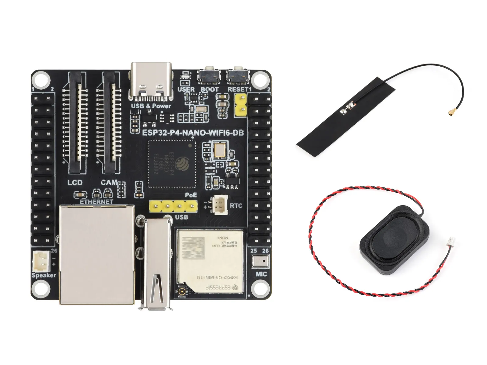
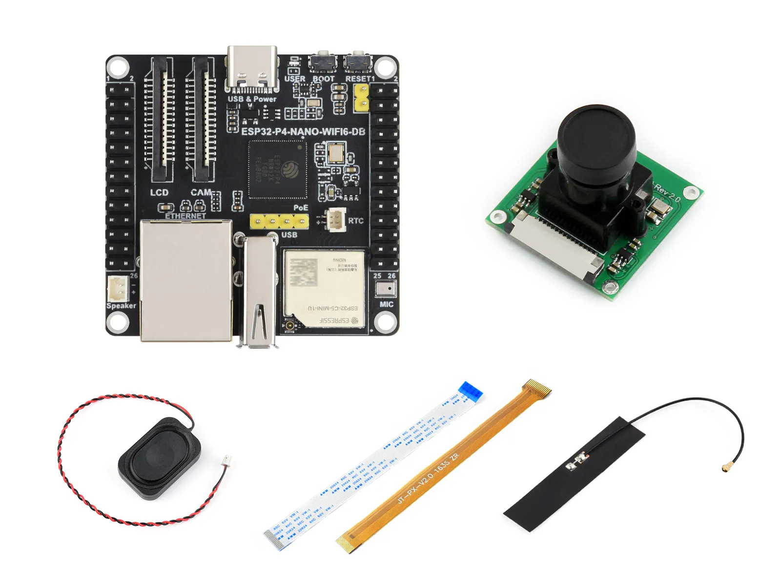
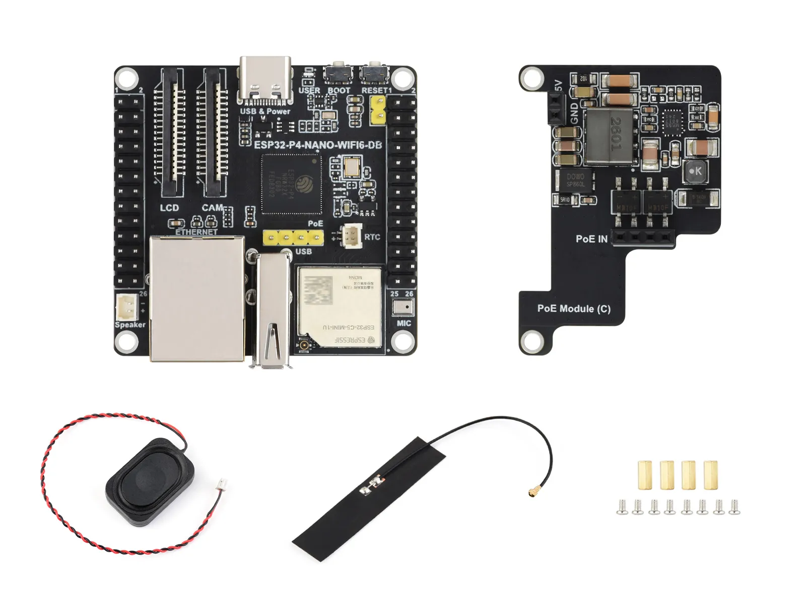
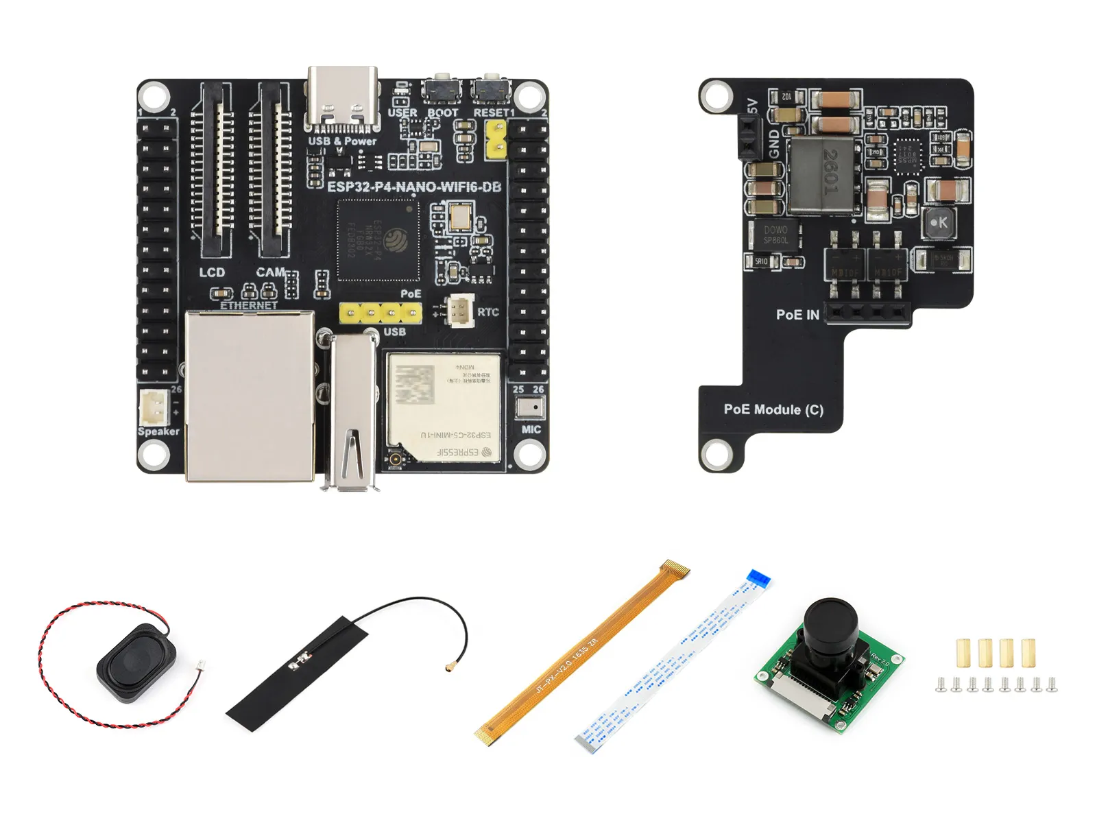
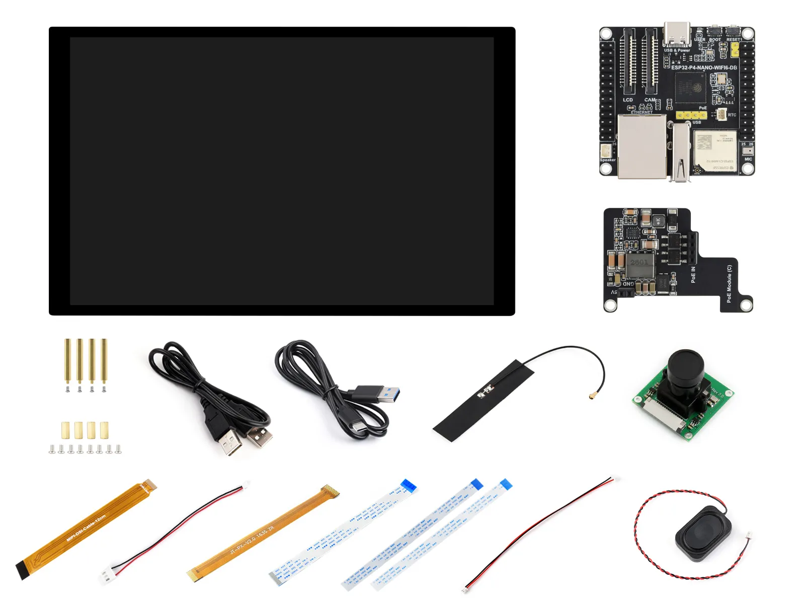
ESP32-P4-NANO-WIFI6-DB is a development board based on the ESP32-P4NRW32X. The board features a dual-core high-performance processor and a single-core low-power processor, and includes an onboard ESP32-C5-MINI-1U wireless module that provides 2.4 GHz / 5 GHz dual-band Wi-Fi 6 and Bluetooth 5 (LE).
The board brings out MIPI-CSI, MIPI-DSI, USB 2.0 OTG, Ethernet, TF, audio, and GPIO interfaces, making it suitable for HMI, edge computing, and I/O expansion applications. Actual functionality is subject to the firmware and software resources provided with this model.
If you are looking for:
- Coding with AI tools: Click Ask AI and select an AI tool to ask questions about this page, or choose Copy page to copy its content and paste it into an AI tool for coding assistance.
- Schematics, datasheets, and example code: See Resources
- Arduino development: See Working with Arduino
- ESP-IDF development: See Working with ESP-IDF
- Troubleshooting: See Product FAQ or contact Technical Support
| SKU | Product |
|---|---|
| 35554 | ESP32-P4-NANO-WIFI6-DB |
| 35555 | ESP32-P4-NANO-WIFI6-DB-KIT-A |
| 35556 | ESP32-P4-NANO-WIFI6-DB-KIT-B |
| 35557 | ESP32-P4-NANO-WIFI6-DB-KIT-C |
| 35559 | ESP32-P4-NANO-WIFI6-DB-KIT-D |
The 10.1inch DSI touchscreen is included only in Kit D. For other kits, if you need a display, you must prepare a compatible display separately; whether the camera module and PoE module are included depends on the corresponding configuration list.
Onboard Resources
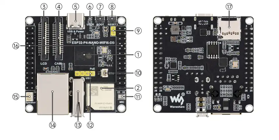
- ESP32-P4NRW32X: Package-on-package with 32 MB PSRAM.
- ESP32-C5-MINI-1U: Provides dual-band Wi-Fi 6 and Bluetooth 5 (LE) via an external antenna.
- Display Interface: MIPI-DSI, 2-lane. Compatible with
5/7/8/10.1-inch DSI screens. - Camera Interface: MIPI-CSI, 2-lane. Compatible with
OV5647camera. - Type-C Port: For 5 V power, program flashing, and serial debugging.
- USER-LED: Power indicator.
- BOOT Button: Press during power-on or reset to enter download mode.
- RESET Button: Resets the board.
- PoE Module Power / External Power Input: For 5 V power input or compatible PoE module.
- RTC Battery Header: For a rechargeable RTC battery (only rechargeable RTC batteries supported).
- Microphone: Onboard audio capture.
- PoE Module Connector: For an optional compatible PoE expansion board.
- Type-A Port: USB 2.0 OTG High-Speed interface.
- 100 Mbps RJ45 Ethernet Port: 100 Mbps Ethernet interface.
- Speaker Header: MX1.25 2P, supports 8 Ω 2 W speakers.
- GPIO Headers: Two 2 × 13, 2.54 mm expansion pin headers.
- TF Card Slot: For local storage and media expansion.
Peripheral Quick Reference
| Module | Device / Function | Interface | Address / Parameters | GPIO / Signals |
|---|---|---|---|---|
| LCD | MIPI-DSI display | MIPI-DSI | 2-lane; supports 5 / 7 / 8 / 10.1-inch panel configurations | LCD reset not connected; backlight controlled via shared I2C |
| Touch | GT911 capacitive touch | I2C | 7-bit address 0x5D / 0x14 | SDA=GPIO7, SCL=GPIO8; RST / INT not connected |
| LCD Backlight | Backlight controller | I2C | 7-bit address 0x45; brightness register 0x96 | SDA=GPIO7, SCL=GPIO8 |
| Camera | MIPI-CSI camera interface | MIPI-CSI + SCCB | 2-lane; camera model and address depend on module documentation | SCCB shared on GPIO7 / GPIO8; XCLK / RESET not connected |
| Audio | ES8311 Codec | I2C + I2S | 7-bit I2C address 0x18; 8-bit write address 0x30; single analog microphone | I2C: SDA=GPIO7, SCL=GPIO8; MCLK=GPIO13, SCLK=GPIO12, WS=GPIO10, DOUT=GPIO9, DIN=GPIO11 |
| Amplifier Control | Onboard speaker amp enable | GPIO | High level to enable | GPIO53 |
| TF Card | SDMMC 4-bit | SDMMC | 4-bit mode | CLK=GPIO43, CMD=GPIO44, D0=GPIO39, D1=GPIO40, D2=GPIO41, D3=GPIO42; power control=GPIO45 |
| Ethernet | IP101GRI PHY | RMII + SMI | PHY address 1; 50 MHz REF_CLK external input | CRS_DV=GPIO28, RXD0=GPIO29, RXD1=GPIO30, MDC=GPIO31, TXD0=GPIO34, TXD1=GPIO35, TX_EN=GPIO49, REF_CLK=GPIO50, RESET=GPIO51, MDIO=GPIO52 |
| ESP32-C5 | ESP-Hosted communication | SDIO | Wi-Fi 6 / Bluetooth 5 (LE) co-processor | CLK=GPIO18, CMD=GPIO19, D0=GPIO14, D1=GPIO15, D2=GPIO16, D3=GPIO17, RESET=GPIO54 |
Pin Definitions
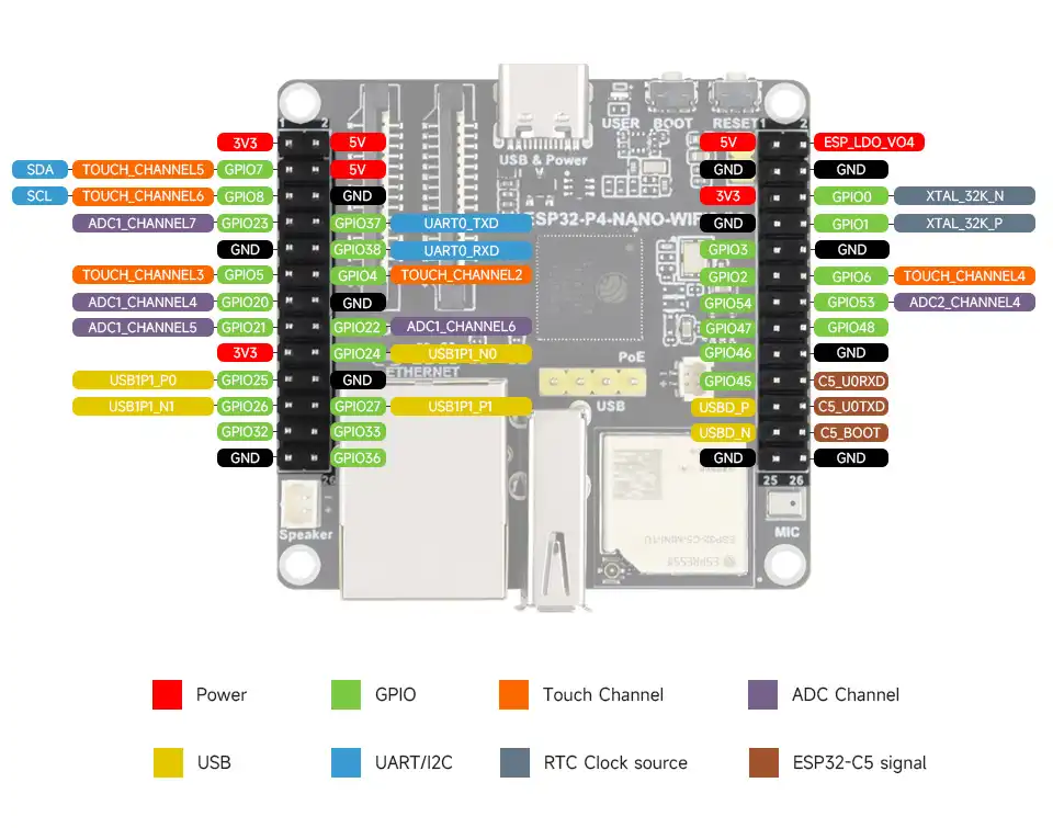
When using the GPIO headers on the ESP32-P4-NANO-WIFI6-DB, note the multiplexed functions marked on the pin diagram. Some GPIOs are already connected to onboard peripherals; before using them as general-purpose I/O, confirm that the corresponding peripheral is not enabled.
Expansion Interface
| Type | Signals |
|---|---|
| Power | 5V / 3V3 / GND |
| I2C | SDA(GPIO7) / SCL(GPIO8) |
| UART | TX(GPIO37) / RX(GPIO38) |
| GPIO | GPIO0 / GPIO1 / GPIO2 / GPIO3 / GPIO4 / GPIO5 / GPIO6 / GPIO20 / GPIO21 / GPIO22 / GPIO23 / GPIO24 / GPIO25 / GPIO26 / GPIO27 / GPIO32 / GPIO33 / GPIO36 / GPIO45 / GPIO46 / GPIO47 / GPIO48 / GPIO53 / GPIO54 |
GPIO Allocation
The table below lists the GPIOs already occupied by onboard circuits and those brought out to expansion headers.
| GPIO | Signal Name | Connected To | Remarks |
|---|---|---|---|
| GPIO0 | GPIO0 | XTAL_32K_N / (reserved pad / pin header) | To use as normal GPIO, consider removing R32 to disable XTAL_32K function |
| GPIO1 | GPIO1 | XTAL_32K_P / (reserved pad / pin header) | To use as normal GPIO, consider removing R36 to disable XTAL_32K function |
| GPIO2 | GPIO2 | Reserved pad / pin header | Expansion header GPIO2 |
| GPIO3 | GPIO3 | Reserved pad / pin header | Expansion header GPIO3 |
| GPIO4 | GPIO4 | Reserved pad / pin header | Expansion header GPIO4 |
| GPIO5 | GPIO5 | Reserved pad / pin header | Expansion header GPIO5 |
| GPIO6 | GPIO | Expansion header / ESP32-C5-MINI-1U | C5 IO02 |
| GPIO7 | I2C SDA | ES8311, GT911, LCD backlight, camera SCCB, expansion header | Shared I2C SDA |
| GPIO8 | I2C SCL | ES8311, GT911, LCD backlight, camera SCCB, expansion header | Shared I2C SCL |
| GPIO9 | I2S DOUT | ES8311 DSDIN | Audio playback data |
| GPIO10 | I2S WS | ES8311 LRCK | Audio frame sync |
| GPIO11 | I2S DIN | ES8311 ASDOUT | Audio capture data |
| GPIO12 | I2S SCLK | ES8311 SCLK | Audio bit clock |
| GPIO13 | I2S MCLK | ES8311 MCLK | Audio master clock |
| GPIO14 | GPIO14 | ESP32-C5-MINI-1U | C5 SDIO D0 |
| GPIO15 | GPIO15 | ESP32-C5-MINI-1U | C5 SDIO D1 |
| GPIO16 | GPIO16 | ESP32-C5-MINI-1U | C5 SDIO D2 |
| GPIO17 | GPIO17 | ESP32-C5-MINI-1U | C5 SDIO D3 |
| GPIO18 | GPIO18 | ESP32-C5-MINI-1U | C5 SDIO CLK |
| GPIO19 | GPIO19 | ESP32-C5-MINI-1U | C5 SDIO CMD |
| GPIO20 | GPIO20 | Reserved pad / pin header | Expansion header GPIO20 |
| GPIO21 | GPIO21 | Reserved pad / pin header | Expansion header GPIO21 |
| GPIO22 | GPIO22 | Reserved pad / pin header | Expansion header GPIO22 |
| GPIO23 | GPIO23 | Reserved pad / pin header | Expansion header GPIO23 |
| GPIO24 | GPIO24 | Reserved pad / pin header | Expansion header GPIO24 / expansion header USB1P1_N0 |
| GPIO25 | GPIO25 | Reserved pad / pin header | Expansion header GPIO25 / expansion header USB1P1_P0 |
| GPIO26 | GPIO26 | Reserved pad / pin header | Expansion header GPIO26 / expansion header USB1P1_N1 |
| GPIO27 | GPIO27 | Reserved pad / pin header | Expansion header GPIO27 / expansion header USB1P1_P1 |
| GPIO28 | GPIO28 | IP101GRI RMII CRS_DV | Carrier sense / receive data valid multiplexed signal, PHY → ESP32-P4 (input) |
| GPIO29 | GPIO29 | IP101GRI RMII RXD0 | Receive data bit 0, PHY → ESP32-P4 (input) |
| GPIO30 | GPIO30 | IP101GRI RMII RXD1 | Receive data bit 1, PHY → ESP32-P4 (input) |
| GPIO31 | GPIO31 | IP101GRI SMI MDC | PHY management interface clock, ESP32-P4 → PHY (output) |
| GPIO32 | GPIO32 | Reserved pad / pin header | Expansion header GPIO32 |
| GPIO33 | GPIO33 | Reserved pad / pin header | Expansion header GPIO33 |
| GPIO34 | GPIO34 | IP101GRI RMII TXD0 | Transmit data bit 0, ESP32-P4 → PHY (output) |
| GPIO35 | GPIO35 | IP101GRI RMII TXD1 / BOOT | Strapping pin; transmit data bit 1, ESP32-P4 → PHY (output) |
| GPIO36 | GPIO36 | Reserved pad / pin header | Strapping pin; external 3.3 V pull-up |
| GPIO37 | UART0_TXD | Expansion header / serial interface | UART0 TX; not recommended for general-purpose use |
| GPIO38 | UART0_RXD | Expansion header / serial interface | UART0 RX; not recommended for general-purpose use |
| GPIO39 | SD_D0 | TF card | SDMMC 4-bit data line |
| GPIO40 | SD_D1 | TF card | SDMMC 4-bit data line |
| GPIO41 | SD_D2 | TF card | SDMMC 4-bit data line |
| GPIO42 | SD_D3 | TF card | SDMMC 4-bit data line |
| GPIO43 | SD_CLK | TF card | SDMMC clock line |
| GPIO44 | SD_CMD | TF card | SDMMC command line |
| GPIO45 | SD_VDD_EN | TF card power control / expansion header | Low to enable; not recommended for general-purpose use while TF function is active |
| GPIO46 | GPIO46 | Reserved pad / pin header | Expansion header GPIO46 |
| GPIO47 | GPIO47 | Reserved pad / pin header | Expansion header GPIO47 |
| GPIO48 | GPIO48 | Reserved pad / pin header | Expansion header GPIO48 |
| GPIO49 | GPIO49 | IP101GRI RMII TX_EN | Transmit enable, ESP32-P4 → PHY (output) |
| GPIO50 | GPIO50 | IP101GRI RMII REF_CLK | 50 MHz RMII reference clock, PHY → ESP32-P4 (input) |
| GPIO51 | GPIO51 | IP101GRI PHY RESET | PHY hardware reset control, ESP32-P4 → PHY (GPIO output) |
| GPIO52 | GPIO52 | IP101GRI SMI MDIO | PHY management interface data, bidirectional |
| GPIO53 | PA_CTRL | NS4150B enable / expansion header | Active high; not recommended for general-purpose use while audio function is active |
| GPIO54 | C5_CHIP_PU | ESP32C5 enable / expansion header | High to enable, low to reset |
LCD and Touch Pins
| Signal | GPIO / Signal | Description |
|---|---|---|
MIPI-DSI | MIPI interface | 2-lane display interface |
LCD_RST | Not connected | No dedicated GPIO for LCD reset |
LCD_BL | I2C 0x45 | Backlight controlled via register 0x96 |
TP_SCL | GPIO8 | GT911 touch I2C SCL, shared bus |
TP_SDA | GPIO7 | GT911 touch I2C SDA, shared bus |
TP_RST | Not connected | GT911 reset signal not connected |
TP_INT | Not connected | GT911 interrupt signal not connected; uses polling mode |
Audio and TF Card
| Signal / Peripheral | GPIO / Signal | Description |
|---|---|---|
I2S_MCLK | GPIO13 | ES8311 master clock |
I2S_SCLK | GPIO12 | ES8311 bit clock |
I2S_WS | GPIO10 | ES8311 frame sync |
I2S_DOUT | GPIO9 | ESP32-P4 output to ES8311 |
I2S_DIN | GPIO11 | ES8311 output to ESP32-P4 |
| Amplifier enable | GPIO53 | Active high |
SD_D0 / SD_D1 | GPIO39 / GPIO40 | SDMMC data lines |
SD_D2 / SD_D3 | GPIO41 / GPIO42 | SDMMC data lines |
SD_CLK / SD_CMD | GPIO43 / GPIO44 | SDMMC clock and command lines |
SD_VDD_EN | GPIO45 | TF card power control, low to enable |
Ethernet Pins
| Signal | GPIO | Direction / Description |
|---|---|---|
RMII_CRS_DV | GPIO28 | IP101GRI → ESP32-P4; carrier sense / receive data valid multiplexed signal |
RMII_RXD0 | GPIO29 | IP101GRI → ESP32-P4; receive data bit 0 |
RMII_RXD1 | GPIO30 | IP101GRI → ESP32-P4; receive data bit 1 |
SMI_MDC | GPIO31 | ESP32-P4 → IP101GRI; PHY management interface clock |
RMII_TXD0 | GPIO34 | ESP32-P4 → IP101GRI; transmit data bit 0 |
RMII_TXD1 | GPIO35 | ESP32-P4 → IP101GRI; transmit data bit 1 |
RMII_TX_EN | GPIO49 | ESP32-P4 → IP101GRI; transmit enable |
RMII_REF_CLK | GPIO50 | IP101GRI → ESP32-P4; 50 MHz RMII reference clock |
PHY_RESET | GPIO51 | ESP32-P4 → IP101GRI; PHY hardware reset control |
SMI_MDIO | GPIO52 | Bidirectional; PHY management interface data |
I2C Device Summary
| Device | Model / Function | I2C Address | I2C Pins | Notes |
|---|---|---|---|---|
| Audio Codec | ES8311 | 7-bit 0x18; 8-bit write address 0x30 | GPIO7 / GPIO8 | Onboard audio capture and playback |
| Touch | GT911 | 0x5D / 0x14 | GPIO7 / GPIO8 | Both addresses are tried; RST / INT not connected |
| LCD Backlight | Backlight controller | 0x45 | GPIO7 / GPIO8 | Brightness register is 0x96 |
| Camera SCCB | External camera module | Depends on module | GPIO7 / GPIO8 | Shares bus with onboard I2C devices |
Precautions
- GPIO7 / GPIO8 are the onboard shared I2C bus. When connecting external I2C devices, confirm that the addresses do not conflict.
- GPIO45 is used for TF card power control, GPIO53 for the audio amplifier, and GPIO54 for ESP32-C5 communication reset; it is not recommended to use these as general-purpose GPIO while the corresponding peripherals are active.
- GPIO28–GPIO31, GPIO34–GPIO35, and GPIO49–GPIO52 are used for Ethernet RMII / SMI and PHY reset; it is not recommended to use them as general-purpose GPIO.
- The LCD reset, GT911 reset, and interrupt signals are not connected; the corresponding control is handled through software in the display or touch drivers.
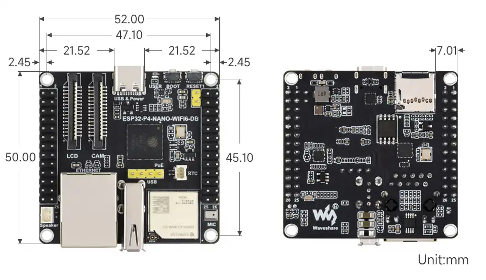
Dimensions
Development Methods
Arduino is generally easier to get started with and more beginner-friendly for hobbyists. ESP-IDF offers a more complete development toolchain and finer-grained system control, making it suitable for complex projects or applications with higher performance requirements.
ESP32-P4 currently has limited adaptation on the Arduino platform. To ensure development stability, it is recommended to use ESP-IDF for development at this stage.
- ESP-IDF, short for Espressif IoT Development Framework, is Espressif's development framework for the ESP series of chips. It is developed using the C language, including a compiler, debugger, and flashing tool, etc., and can be developed via the command lines or through an integrated development environment (such as Visual Studio Code with the Espressif IDF plugin). The plugin offers features such as code navigation, project management, and debugging, etc. We recommend using VS Code for development. For detailed configuration steps, refer to the ESP-IDF (VS Code) Development Environment Setup Guide, which also provides relevant example programs for reference.