ESP32-P4-WIFI6-DEV-KIT
- Development Board
- Kit A
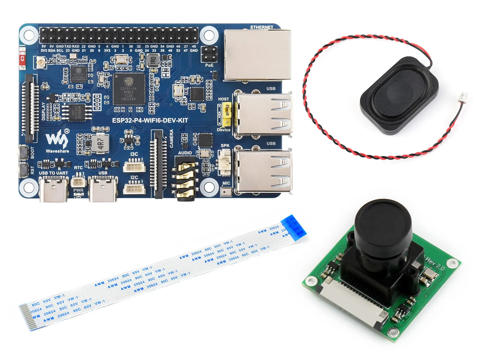
- KIT B
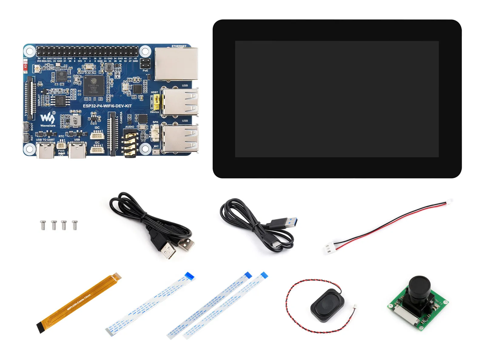
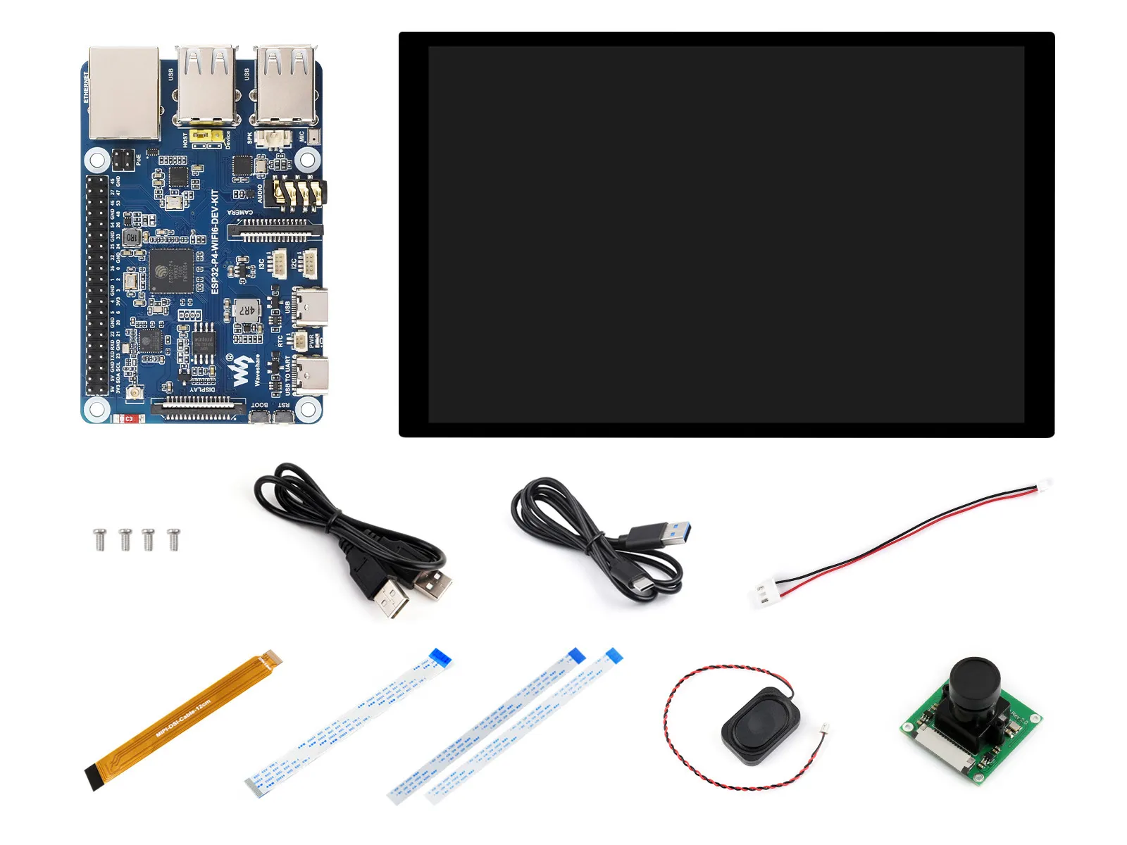
- KIT C
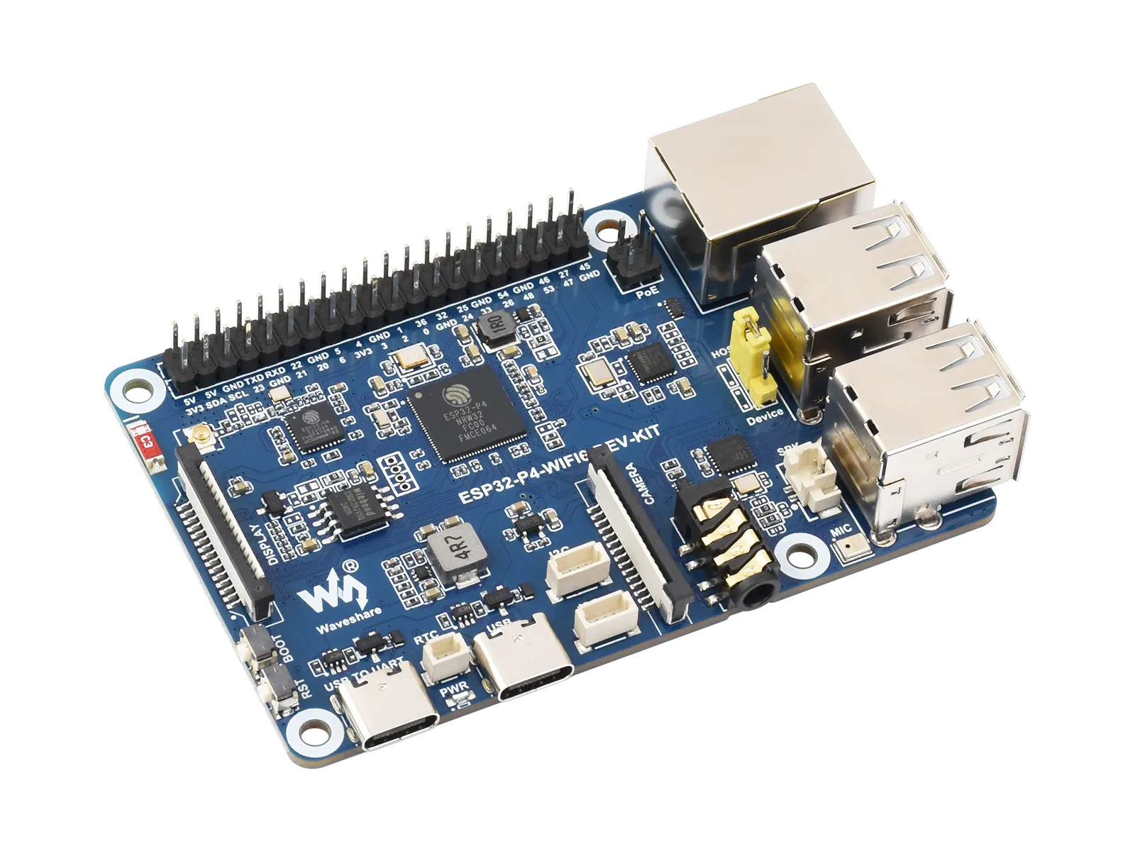
This product is a high-performance development board based on the ESP32-P4, featuring a dual-core plus single-core RISC-V architecture. It supports rich human-machine interaction interfaces, including MIPI-CSI (with an integrated Image Signal Processor, ISP) and MIPI-DSI interfaces, as well as common peripherals such as SPI, I2S, I2C, LED PWM, MCPWM, RMT, ADC, UART, and TWAI. It also features USB OTG 2.0 HS, Ethernet, and SDIO Host 3.0 for high-speed connectivity. The ESP32-P4 chip integrates a digital signature peripheral and a dedicated key management unit to ensure data and operation security. The ESP32-P4-WIFI6-DEV-KIT is designed for high-performance and high-security applications, and fully meets the higher requirements of embedded applications for human-computer interface support, edge computing capabilities, and I/O connectivity features.
| SKU | Product |
|---|---|
| 32054 | ESP32-P4-WIFI6-DEV-KIT |
| 32055 | ESP32-P4-WIFI6-DEV-KIT-A |
| 32056 | ESP32-P4-WIFI6-DEV-KIT-B |
| 32057 | ESP32-P4-WIFI6-DEV-KIT-C |
Features
- Processor
- Equipped with a RISC-V 32-bit dual-core processor (HP system), featuring DSP and ISA extensions, a Floating-Point Unit (FPU), with a main frequency of up to 360 MHz.
- Equipped with a RISC-V 32-bit single-core processor (LP system), with a main frequency of up to 40 MHz.
- Equipped with an ESP32-C6 WIFI/BT co-processor, expanding WIFI 6/Bluetooth 5 and other functions through SDIO
- Memory
- 128 KB of high-performance (HP) system read-only memory (ROM).
- 16 KB of low-power (LP) system read-only memory (ROM).
- 768 KB of high-performance (HP) L2 memory (L2MEM).
- 32 KB of low-power (LP) SRAM.
- 8 KB of system tightly coupled memory (TCM).
- 32 MB PSRAM stacked in the package, plus 16 MB Nor Flash externally
- Peripheral Interfaces
- 2×20 headers bring out 28 remaining programmable GPIOs, supporting a wide range of peripherals
- Onboard Type-A USB 2.0 OTG interface, 100Mbps Ethernet interface, SDIO3.0 TF card slot, Type-C UART programming port for convenient use in different scenarios
- Onboard speaker interface, microphone, 3.5mm headphone jack, the Codec chip and power amplifier chip can be used to achieve the ideal audio function requirements
- Onboard MIPI-CSI high-definition camera interface, supporting Full HD 1080P image capture and encoding, integrated Image Signal Processor (ISP), H.264 video encoder, supports H.264 & JPEG video encoding (1080P @30fps), facilitating applications in computer vision, machine vision, and other fields
- Onboard MIPI-DSI high-definition display interface, integrated Pixel Processing Accelerator (PPA), 2D graphics acceleration controller (2D DMA), supports JPEG image decoding (1080P @30fps), providing strong support for high-definition display and smooth HMI experiences, suitable for applications such as smart home control panels, industrial control panels, and vending machines
- The reserved PoE module interface, making the board's power supply more flexible. With only a single Ethernet cable connected to a PoE device, the board can achieve both networking and power delivery
Hardware Description
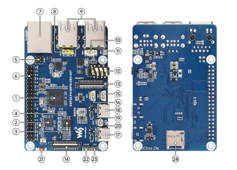
- ESP32-P4NRW32 ESP32-P4 with 32MB stacked PSRAM
- ESP32-C6 SDIO interface protocol, expands ESP32-P4 with Wi-Fi 6, Bluetooth 5 (LE)
- 16MB Nor Flash
- ESP32-C6 UART Pads
- PoE Module Interface Can be connected to an external PoE module for PoE power supply
- 40PIN GPIO Header
- 100M RJ45 Ethernet Port
- USB OTG Function Selection Can switch to HOST to expand USB ports
- USB-A Ports USB OTG 2.0 High Speed interface, function can be switched via jumper cap
- Speaker Header MX1.25 2P connector, supports 8Ω 2W speaker
- SMD Microphone
- 3.5mm Audio Jack Supports audio playback via connected headphones
- Camera Interface MIPI-CSI (2-lane), supports OV5647 camera, etc.
- Display Interface MIPI-DSI (2-lane). For the list of compatible displays, please refer to FAQ
- I2C Interface
- I3C Interface
- Type-C UART Port For power supply, programming, and debugging
- Type-C USB Port For power supply and programming
- RTC Battery Header For connecting a rechargeable RTC battery (only rechargeable batteries supported)
- PWR Power supply indicator
- ESP32-C6 SMD Antenna
- BOOT Button Press during power-up or reset to enter download mode
- RESET Button reset button
- TF Card Slot SDIO 3.0 interface protocol
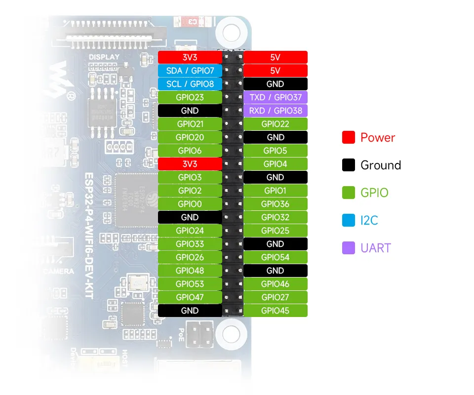
Pinout Definition
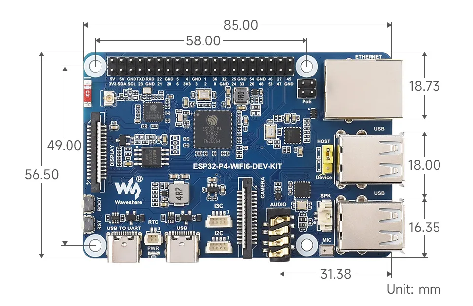
Dimensions
Development Tools
Each of these two development approaches has its own advantages, and developers can choose according to their needs and skill levels. Arduino is suitable for beginners and non-professionals because they are easy to learn and quick to get started. ESP-IDF is a better choice for developers with a professional background or high performance requirements, as it provides more advanced development tools and greater control capabilities for the development of complex projects.
ESP32-P4 currently has limited adaptation on the Arduino platform. To ensure development stability, it is recommended to use ESP-IDF for development at this stage. If you have requirements for using the Arduino platform, you can participate in the discussion on GitHub: Support of Arduino
- ESP-IDF, short for Espressif IoT Development Framework, is a development framework provided by Espressif for the ESP series chips. It is developed using the C language, including a compiler, debugger, and flashing tool, etc., and can be developed via the command lines or through an integrated development environment (such as Visual Studio Code with the Espressif IDF plugin). The plugin offers features such as code navigation, project management, and debugging, etc. We recommend using VS Code for development. For the specific configuration process, please refer to the Working with ESP-IDF. The tutorial also provides relevant example programs for reference.