ESP32-P4-WIFI6-Touch-LCD-4B
- Onboard camera interface
- Onboard Ethernet port + RS485 + 2-ch relay
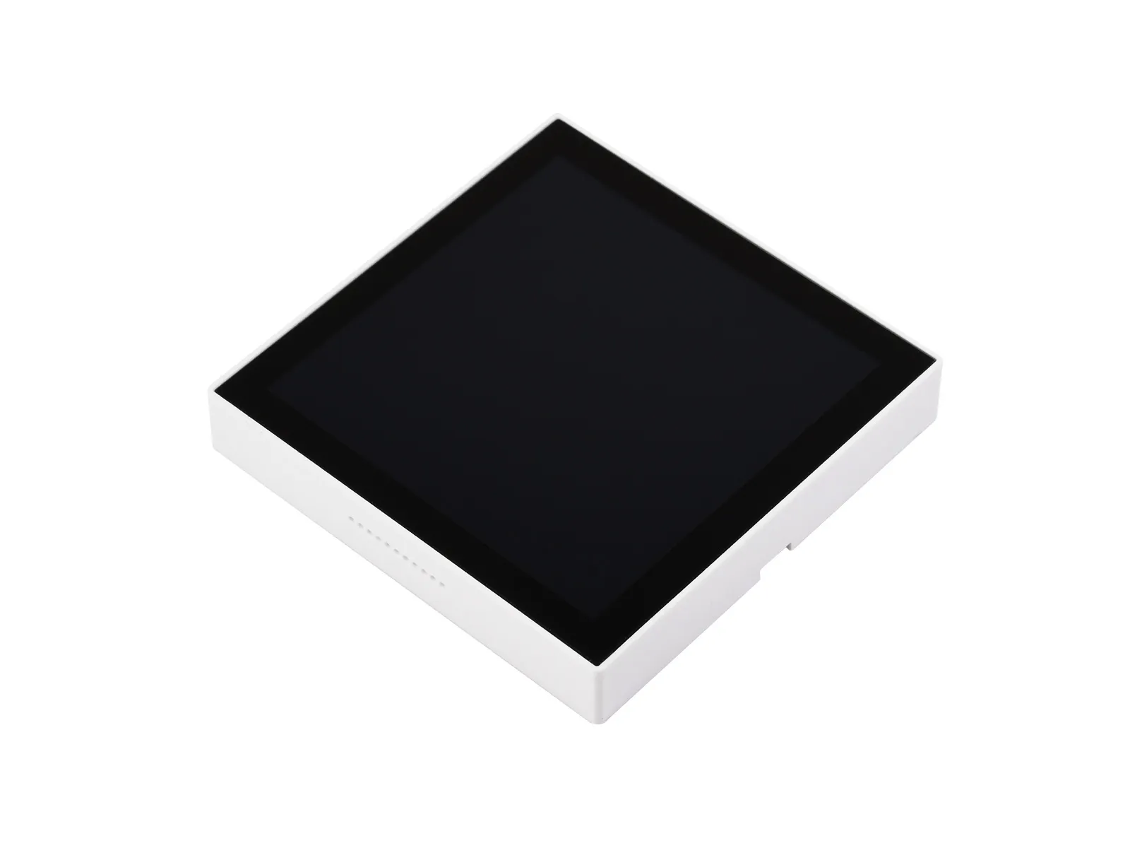
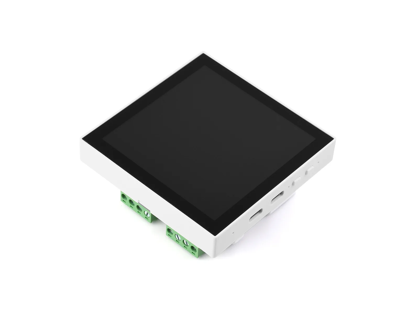
This series is a high-performance development board based on the ESP32-P4 chip. This series adopts a dual-core plus single-core RISC-V architecture design, featuring a built-in 4inch 720 × 720 resolution IPS touch display. It supports rich human-machine interaction interfaces, including MIPI-CSI with an integrated image signal processor (ISP), and USB OTG 2.0 HS port for high-speed connections. The ESP32-P4 chip integrates a digital signature peripheral and a dedicated key management unit to ensure data and operational security. It is designed for high performance and high security applications, and fully meets the higher requirements of embedded applications for human-computer interface support, edge computing capabilities and IO connection features.
| SKU | Product |
|---|---|
| 31416 | ESP32-P4-WIFI6-Touch-LCD-4B |
| 31570 | ESP32-P4-86-Panel-ETH-2RO |
Features
- Processor
- Equipped with a RISC-V 32-bit dual-core processor (HP system), featuring DSP and ISA extensions, a Floating-Point Unit (FPU), with a main frequency of up to 360 MHz.
- Equipped with a RISC-V 32-bit single-core processor (LP system), with a main frequency of up to 40 MHz.
- Equipped with an ESP32-C6 WIFI/BT co-processor, expanding WIFI 6/Bluetooth 5 and other functions through SDIO
- Memory
- 128 KB of high-performance (HP) system read-only memory (ROM).
- 16 KB of low-power (LP) system read-only memory (ROM).
- 768 KB of high-performance (HP) L2 memory (L2MEM).
- 32 KB of low-power (LP) SRAM.
- 8 KB of system tightly coupled memory (TCM).
- 32 MB PSRAM stacked in the package, plus 32 MB Nor Flash externally
- Peripheral Interfaces
- Onboard interfaces include MIPI-CSI, MIPI-DSI, USB 2.0 OTG, Ethernet, SDIO 3.0 TF card slot, dual microphones with echo cancellation, speaker terminal, RTC battery terminal, etc. (different products expose different subsets; refer to the resource introduction)
Hardware Version Comparison
ESP32-P4-WIFI6-Touch-LCD-4B
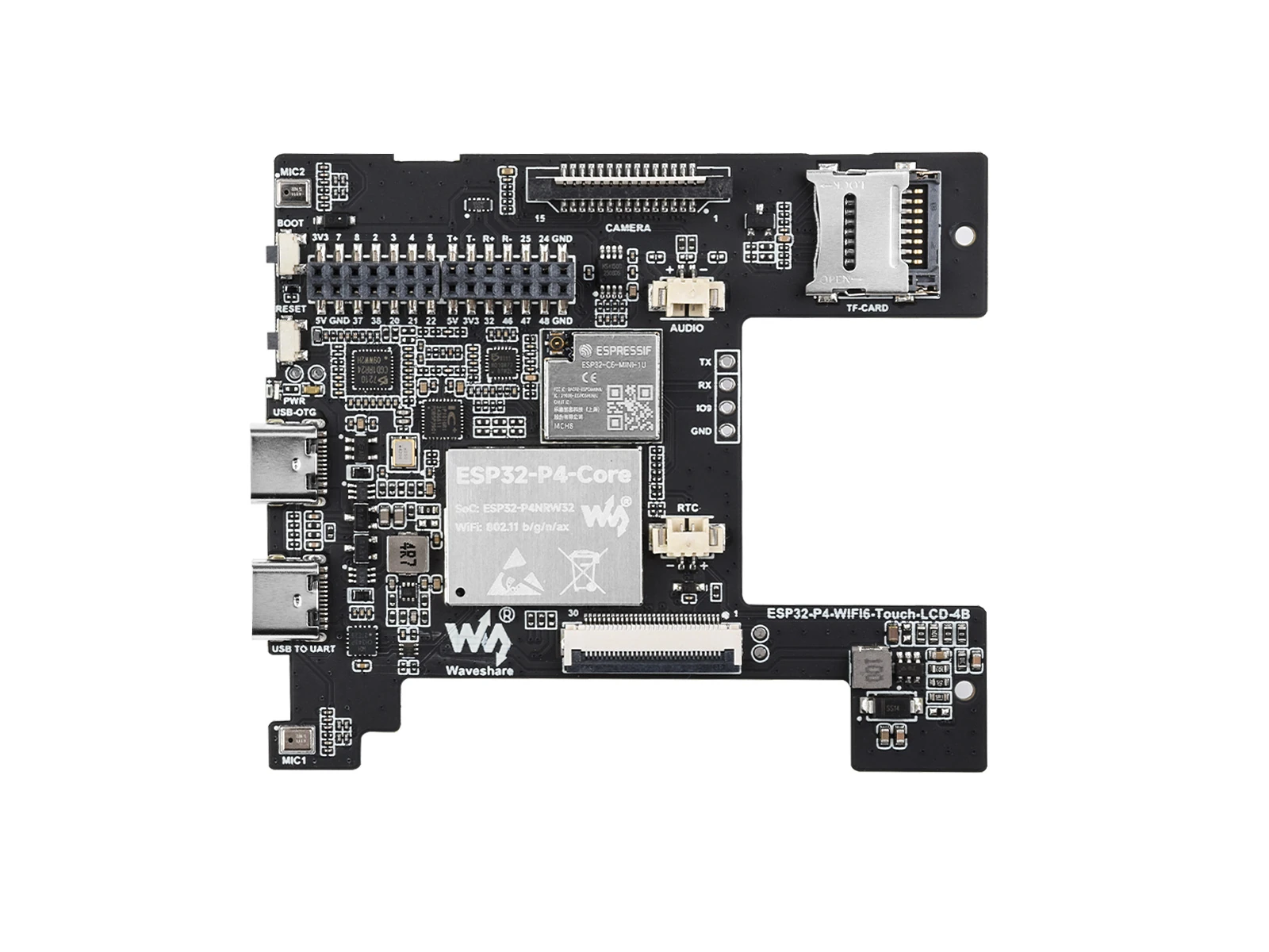
This version is fitted with the 15-pin MIPI CSI camera connector.
ESP32-P4-86-Panel-ETH-2RO
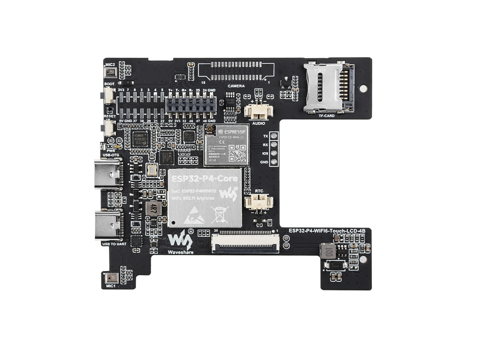
The main PCB does not have the MIPI CSI camera connector fitted. It connects to the 86 Panel Bottom Board, which provides the RJ45 Ethernet port, RS485 interface, and two relays.
The two versions use different main-PCB assemblies and enclosure structures. They cannot share the same 86-type back box.
Onboard Resources
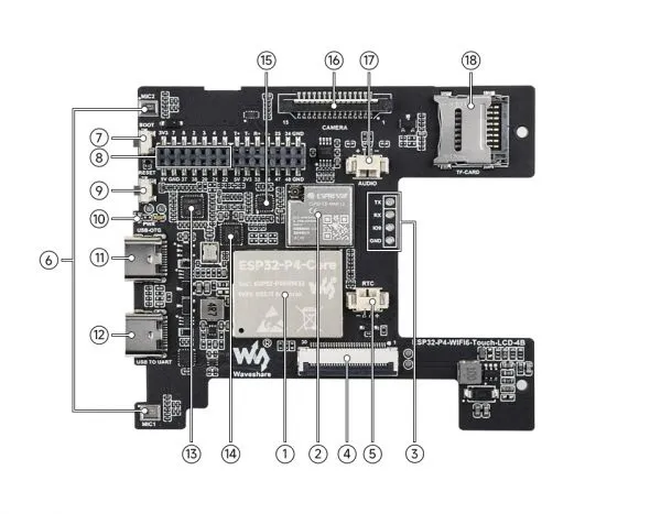
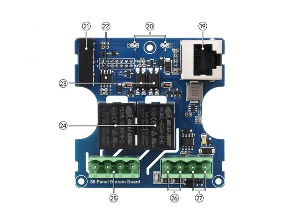
- ESP32-P4-Core Integrates ESP32-P4NRW32 and 32 MB Nor Flash
- ESP32-C6-MINI-1U-H8 Module SDIO interface protocol, expands the development board with Wi-Fi 6, Bluetooth 5 (LE)
- 2.54 mm 4-pin Pads For flashing firmware to the ESP32-C6 module
- MIPI DSI LCD Interface For connecting the MIPI 4-inch screen
- RTC Battery Header For connecting a rechargeable RTC battery (only supports rechargeable RTC batteries)
- Onboard Microphone Microphone input and echo cancellation
- BOOT Button Press during power-up or reset to enter download mode
- Expansion Header (2.0 mm pitch) Can be used to connect the 86 Panel Bottom Board or external I/O
- RESET Button
- PWR LED Indicator Power indicator
- Type-C Interface (USB OTG) USB OTG 2.0 High Speed interface
- Type-C Interface (USB TO UART) For power supply, programming, and debugging
- ES7210 Audio ADC Works with the onboard acoustic echo cancellation circuit for microphone input
- IP101 10/100M Ethernet PHY
- ES8311 Low-Power Audio Codec Chip For audio encoding and decoding
- MIPI CSI Interface 15-pin, 1.0 mm pitch, supports 2-lane MIPI CSI cameras (only available on the ESP32-P4-WIFI6-Touch-LCD-4B version)
- Speaker Header MX1.25 2P connector, supports an 8 Ω, 2 W speaker
- TF Card Slot SDIO 3.0 interface protocol
- 100M RJ45 Ethernet Port
- Relay Indicators
- Power isolation module
- Digital isolator
- Optocoupler isolation
- Relay
- Relay screw terminal 5.08 mm 4-pin
- RS485 screw terminal
- Power screw terminal DC 6-30 V wide-range input
Peripheral Quick Reference
The assignments below are taken from the main-board and 86 Panel Bottom Board schematics linked on the Resources page.
| Module | Device / Function | Interface | GPIO / Signal | Availability |
|---|---|---|---|---|
| LCD | 4-inch 720 x 720 IPS display | 2-lane MIPI DSI | RESET=GPIO27, BL_EN=GPIO33, BL_PWM=GPIO26 | Both versions |
| Touch | GT911 5-point capacitive touch | I2C | SDA=GPIO7, SCL=GPIO8, RST=GPIO23; TP_INT is routed to test point TP2 | Both versions |
| Camera | 15-pin, 1.0 mm pitch camera connector | 2-lane MIPI CSI + I2C | Dedicated CSI lanes; control bus uses GPIO7/GPIO8 | ESP32-P4-WIFI6-Touch-LCD-4B only |
| Wireless | ESP32-C6-MINI-1U-H8 | SDIO / control | GPIO6, GPIO14, GPIO16, GPIO18-GPIO20, GPIO22, GPIO54 | Both versions |
| MicroSD | TF card slot | 4-bit SDIO | D0-D3=GPIO39-GPIO42, CLK=GPIO43, CMD=GPIO44, power control=GPIO45 | Both versions |
| Audio output | ES8311 codec + NS4150B amplifier | I2C + I2S | I2C=GPIO7/GPIO8; I2S=GPIO9-GPIO13; amplifier control=GPIO53 | Both versions |
| Audio input | ES7210 dual-microphone ADC | I2C + I2S/TDM | I2C address 0x40; data and clocks use GPIO10-GPIO13 | Both versions |
| Ethernet PHY | IP101 | RMII | GPIO28-GPIO31, GPIO34/GPIO35, GPIO49-GPIO52 | PHY on both; RJ45 on ESP32-P4-86-Panel-ETH-2RO only |
| RS485 | THVD1406DR / SP3485EEN transceiver | UART, automatic direction control | TXD=GPIO47, RXD=GPIO48 | ESP32-P4-86-Panel-ETH-2RO only |
| Relays | Two optocoupler-isolated relay channels | GPIO | RELAY1=GPIO32, RELAY2=GPIO46 | ESP32-P4-86-Panel-ETH-2RO only |
| USB OTG | ESP32-P4 native USB 2.0 HS | USB | Dedicated USBD_P/USBD_N pins | Both versions |
| USB to UART | CH343P | UART | GPIO37/GPIO38; DTR/RTS also drive the reset/download circuit | Both versions |
Pin Definition
General Expansion Header (P3)
| Pin | Signal | Pin | Signal |
|---|---|---|---|
| 1 | 3V3 | 2 | 5V |
| 3 | GPIO7 / I2C_SDA | 4 | GND |
| 5 | GPIO8 / I2C_SCL | 6 | GPIO37 |
| 7 | GPIO2 | 8 | GPIO38 |
| 9 | GPIO3 | 10 | GPIO20 |
| 11 | GPIO4 | 12 | GPIO21 |
| 13 | GPIO5 | 14 | GPIO22 |
Bottom Board Header (P2)
The P2 header carries Ethernet pairs and control signals between the main PCB and the 86 Panel Bottom Board.
| Pin | Signal | Pin | Signal |
|---|---|---|---|
| 1 | ETH_TX_P / TD_P | 2 | 5V |
| 3 | ETH_TX_N / TD_N | 4 | 3V3 |
| 5 | ETH_RX_P / RD_P | 6 | GPIO32 / RELAY1 |
| 7 | ETH_RX_N / RD_N | 8 | GPIO46 / RELAY2 |
| 9 | USB_IN1_P | 10 | GPIO47 / RS485_TXD |
| 11 | USB_IN1_N | 12 | GPIO48 / RS485_RXD |
| 13 | GND | 14 | GND |
GPIO Allocation
| GPIO | Signal / Connected Device | Notes |
|---|---|---|
| GPIO2-GPIO5 | P3 expansion header | General-purpose expansion pins |
| GPIO6 | ESP32-C6 IO2 | Wireless coprocessor interface |
| GPIO7 | Shared I2C SDA | Touch, camera control, ES8311, and ES7210; also exposed on P3 |
| GPIO8 | Shared I2C SCL | Touch, camera control, ES8311, and ES7210; also exposed on P3 |
| GPIO9 | ES8311 DSDIN | Audio playback data |
| GPIO10 | ES8311 LRCK / ES7210 SDOUT1 | Shared audio interface |
| GPIO11 | ES7210 SDOUT2 | Microphone ADC data |
| GPIO12 | ES8311 ASDOUT / ES7210 LRCK | Shared audio interface |
| GPIO13 | ES8311 / ES7210 SCLK | Audio bit clock |
| GPIO14 | ESP32-C6 IO23 | Wireless coprocessor interface |
| GPIO16 | ESP32-C6 IO22 | Wireless coprocessor interface |
| GPIO18 | ESP32-C6 IO21 | Wireless coprocessor interface |
| GPIO19 | ESP32-C6 IO20 | Wireless coprocessor interface |
| GPIO20 | ESP32-C6 IO19 / P3 | Shared with the expansion header |
| GPIO21 | P3 expansion header | General-purpose expansion pin |
| GPIO22 | ESP32-C6 IO9 / P3 | Shared with the expansion header |
| GPIO23 | TP_RST | GT911 touch reset |
| GPIO24/GPIO25 | USB_IN1_P/USB_IN1_N | Routed to P2 through unpopulated series resistors |
| GPIO26 | LCD_BL_PWM | LCD backlight brightness control |
| GPIO27 | LCD_RESET | LCD reset |
| GPIO28 | IP101 CRS_DV/RX_DV | RMII |
| GPIO29 | IP101 RXD0 | RMII |
| GPIO30 | IP101 RXD1 | RMII |
| GPIO31 | IP101 MDC | RMII management clock |
| GPIO32 | RELAY1 | P2; used by the 86 Panel Bottom Board |
| GPIO33 | BL_EN | LCD backlight boost enable |
| GPIO34 | IP101 TXD0 | RMII |
| GPIO35 | IP101 TXD1 / BOOT button | Shared through the download-mode circuit |
| GPIO37/GPIO38 | CH343P UART / P3 | Programming and debugging serial port, also exposed on P3 |
| GPIO39-GPIO42 | MicroSD D0-D3 | 4-bit SDIO data bus |
| GPIO43 | MicroSD CLK | SDIO clock |
| GPIO44 | MicroSD CMD | SDIO command |
| GPIO45 | MicroSD power control | Controls SD1_VDD |
| GPIO46 | RELAY2 | P2; used by the 86 Panel Bottom Board |
| GPIO47/GPIO48 | RS485 TXD/RXD | P2; used by the 86 Panel Bottom Board |
| GPIO49 | IP101 TXEN | RMII transmit enable |
| GPIO50 | IP101 REF_CLK | RMII reference clock |
| GPIO51 | IP101 RESET | Ethernet PHY reset |
| GPIO52 | IP101 MDIO | RMII management data |
| GPIO53 | PA_CTRL | NS4150B speaker amplifier control |
| GPIO54 | ESP32-C6 CHIP_PU | Wireless coprocessor reset / enable |
Usage Notes
GPIO7/GPIO8are shared by the onboard I2C devices and the P3 header. Check for address conflicts before adding another I2C device.GPIO20,GPIO22,GPIO37, andGPIO38are exposed on P3 but are already connected to onboard functions.GPIO32,GPIO46,GPIO47, andGPIO48become relay and RS485 signals when the 86 Panel Bottom Board is connected.TP_INTis available at test pointTP2and is not connected to an ESP32-P4 GPIO in the referenced schematic.
Dimensions

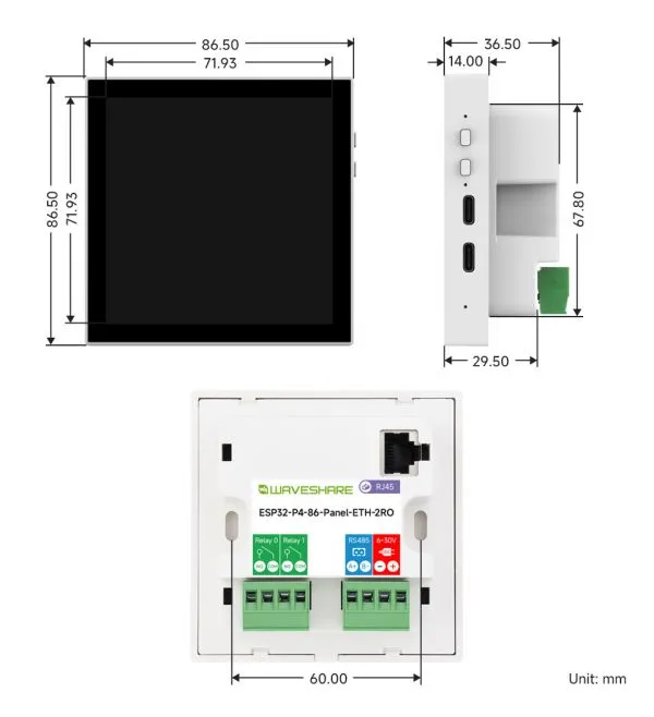
Development Tools
Arduino generally offers a gentler learning curve and may be more approachable for beginners and hobbyists. ESP-IDF provides advanced tooling and finer control over system behavior, making it better suited to complex projects and applications with demanding performance requirements.
Due to the limited support for ESP32-P4 on the Arduino platform, ESP-IDF is currently recommended for development.
- ESP-IDF, short for Espressif IoT Development Framework, is a development framework provided by Espressif for the ESP series chips. It is developed using the C language, including a compiler, debugger, and flashing tool, etc., and can be developed via the command lines or through an integrated development environment (such as Visual Studio Code with the Espressif IDF plugin). The plugin offers features such as code navigation, project management, and debugging, etc. We recommend using VS Code for development. For the specific configuration process, please refer to the Working with ESP-IDF. The tutorial also provides relevant example programs for reference.