AMOLED
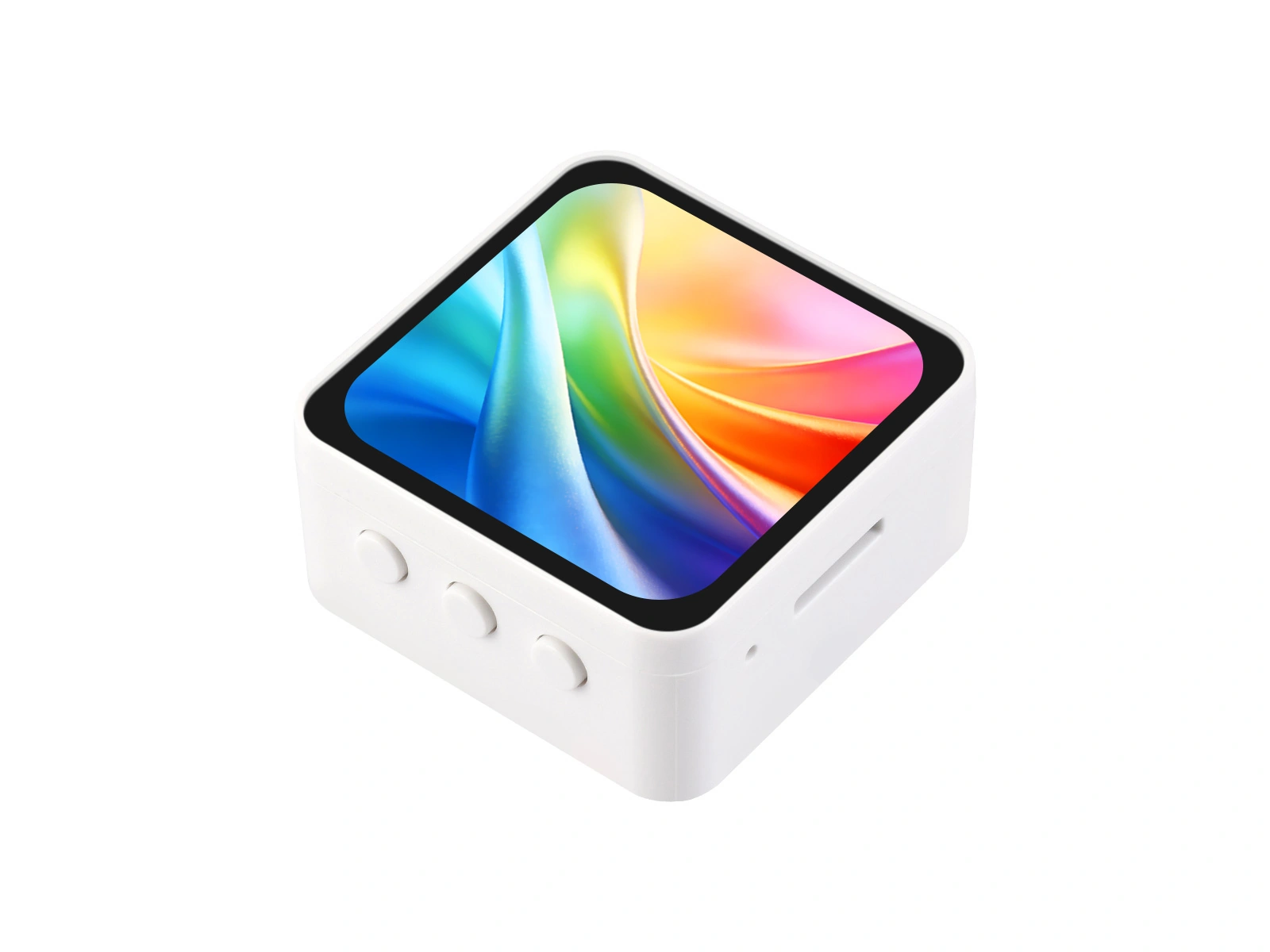
An AMOLED (active-matrix organic light-emitting diode) panel is a self-emissive OLED driven by an active matrix. It provides high contrast, full color, high resolution, and fast response, and this type of display is widely used in smartwatches. As the price of compact AMOLED modules has fallen in recent years, it has become increasingly common to build high-pixel-density color interactive devices on the ESP32 platform.
This page focuses on the bandwidth and memory requirements created by its high resolution.
1. Operating Principle
AMOLED and the PMOLED (passive-matrix OLED) panels described in OLED use the same self-emissive organic-LED principle. Their addressing methods differ:
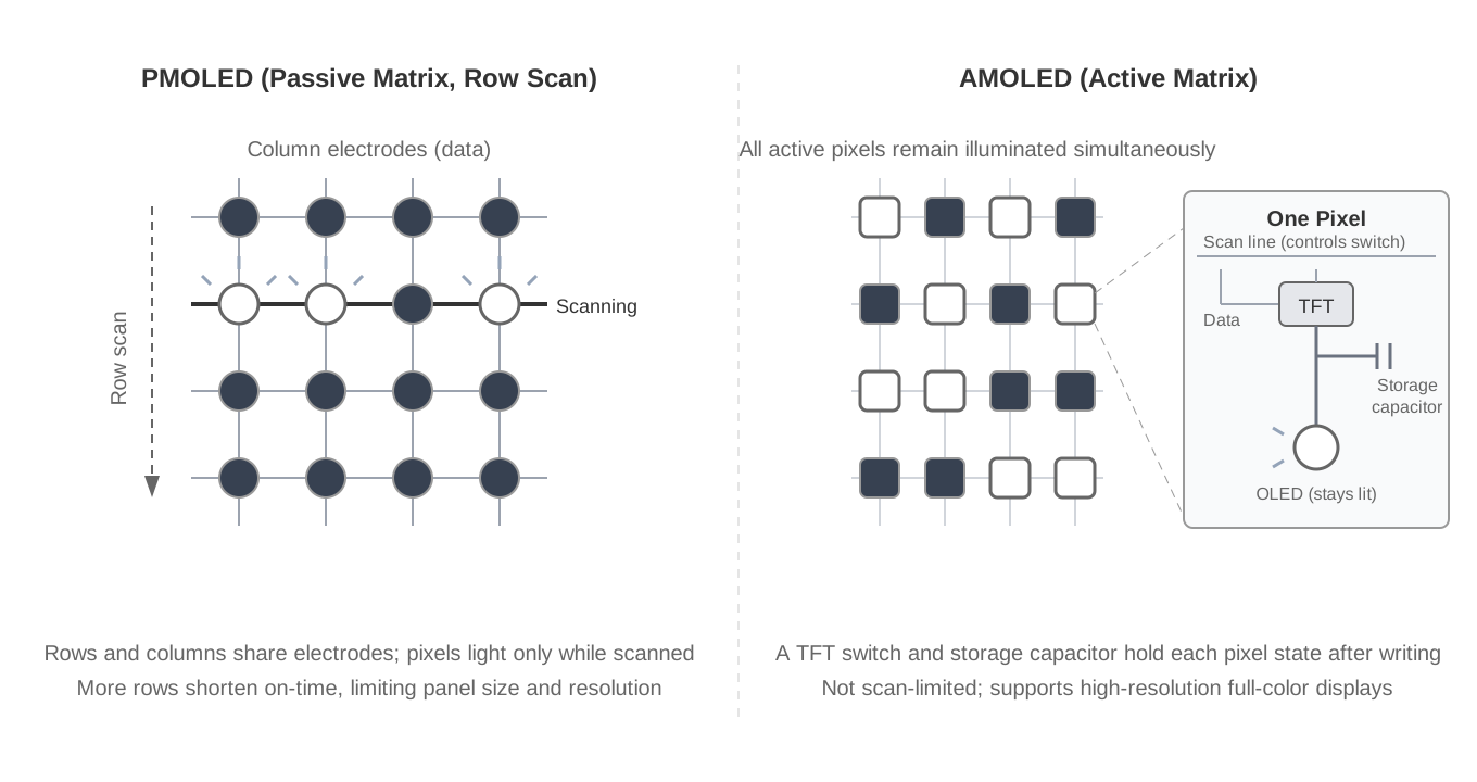
- PMOLED: Rows and columns share electrodes, and only one row is illuminated at a time. As row count increases, each row receives less on-time and requires greater peak current to maintain brightness. This limits brightness and resolution and makes the technology best suited to compact monochrome panels.
- AMOLED: A TFT (thin-film transistor) backplane provides every pixel with a switching transistor and storage capacitor. Once written, a pixel can remain illuminated for the complete frame period. High-resolution, high-brightness, full-color panels are therefore practical.
Black pixels remain completely off, producing very high contrast. Power varies with image content, so a dark interface uses substantially less power than a bright one. This is why smartwatches commonly use watch faces with black backgrounds.
2. Advantages and Limitations
Advantages:
- High contrast and color performance with up to 16.7 million RGB888 colors.
- High resolution and pixel density.
- Fast response and less motion blur than LCD.
- Thin panels that can be cut into round, rounded-corner, and other nonrectangular shapes, making them well suited to watch products.
- Low consumption for dark, always-on interfaces.
Limitations:
- Higher cost than LCD at the same size.
- Burn-in risk from fixed, bright content shown for prolonged periods.
- Greater microcontroller requirements: High resolution increases draw-buffer and interface-bandwidth requirements. A full GUI commonly uses ESP32-S3 with PSRAM (see Display Fundamentals and Interfaces).
3. Common Controllers and Interfaces
AMOLED controllers found in ESP32 products include SH8601, CO5300, and RM690B0. They include GRAM (see Display Fundamentals and Interfaces) and commonly use QSPI. The reason can be seen from the bandwidth estimate described in Display Fundamentals and Interfaces.
For a 2.16-inch, 480×480 display in RGB565 format, one frame is approximately 450 KB, or 3.7 Mbit:
| Interface | Bandwidth at an 80 MHz clock | Theoretical maximum frame rate |
|---|---|---|
| SPI, one data line | 80 Mbps | Approximately 22 FPS |
| QSPI, four data lines | 320 Mbps | Approximately 87 FPS |
These limits count pixel data only. Commands, addresses, chip-select gaps, and software overhead reduce the actual frame rate. Single-line SPI can handle static interfaces and partial updates at this resolution but has little bandwidth for full-screen animation. QSPI transfers four data bits in parallel and is therefore common on compact AMOLED modules with GRAM. Higher-resolution products, such as 720×1280 panels, use MIPI-DSI, which is supported only by ESP32-P4.

Memory requirements depend on draw-buffer size. LVGL (a GUI framework) does not require a complete framebuffer and recommends a buffer of at least roughly one tenth of the screen. Only Direct mode and full-frame double buffering require complete frames. One 480×480 RGB565 frame is 480 × 480 × 2 = 460800 bytes, approximately 450 KB, already close to the ESP32-S3's total on-chip SRAM. Full-frame buffering therefore requires PSRAM, while a partial buffer may not; the board's official LVGL example uses two quarter-screen buffers. When selecting a development board, confirm that its PSRAM capacity is sufficient for the chosen buffering scheme, and enable the PSRAM option that matches the module in the project settings, which is OPI PSRAM for this board.
Two other differences from LCD are important:
- No backlight pin: An AMOLED is self-emissive, so brightness is set with a controller command rather than PWM on a BL pin.
- Some module initialization sequences contain manufacturer-tuned gamma and power parameters. Use the official initialization sequence for the exact panel revision rather than reusing one directly across different modules.
4. Arduino_GFX Example
The Waveshare ESP32-S3-Touch-AMOLED-2.16 includes a 2.16-inch, 480×480 capacitive-touch AMOLED with a CO5300 display controller and CST9220 touch controller. It also integrates power management, an IMU (Inertial Measurement Unit), an RTC (Real-Time Clock), audio, and other peripherals.
4.1 Preparation
- Install the Arduino IDE and ESP32 board support using Arduino IDE Setup.
- Install
GFX Library for ArduinoandU8g2from Library Manager. The former drives the display and the latter supplies fonts. Verify the versions listed below. - Select
ESP32S3 Dev Module.
| Package | Verified version |
|---|---|
| arduino-esp32 | v3.3.10 |
| GFX Library for Arduino | v1.6.6 |
| U8g2 | v2.36.19 |
This chapter covers only the display, so only these two libraries are required. The touch, IMU, RTC, audio, and other peripherals use their own driver libraries. See the corresponding peripheral chapters, or obtain the official examples from Resources and Documents.
4.2 Confirm the Pins
| Signal | GPIO | Description |
|---|---|---|
| LCD_SDIO0 | GPIO4 | QSPI data 0 |
| LCD_SDIO1 | GPIO5 | QSPI data 1 |
| LCD_SDIO2 | GPIO6 | QSPI data 2 |
| LCD_SDIO3 | GPIO7 | QSPI data 3 |
| LCD_SCLK | GPIO38 | QSPI clock |
| LCD_CS | GPIO12 | Chip select |
| LCD_RESET | GPIO39 | Reset |
There is no LCD_BL pin because the AMOLED is self-emissive.
4.3 Example Code
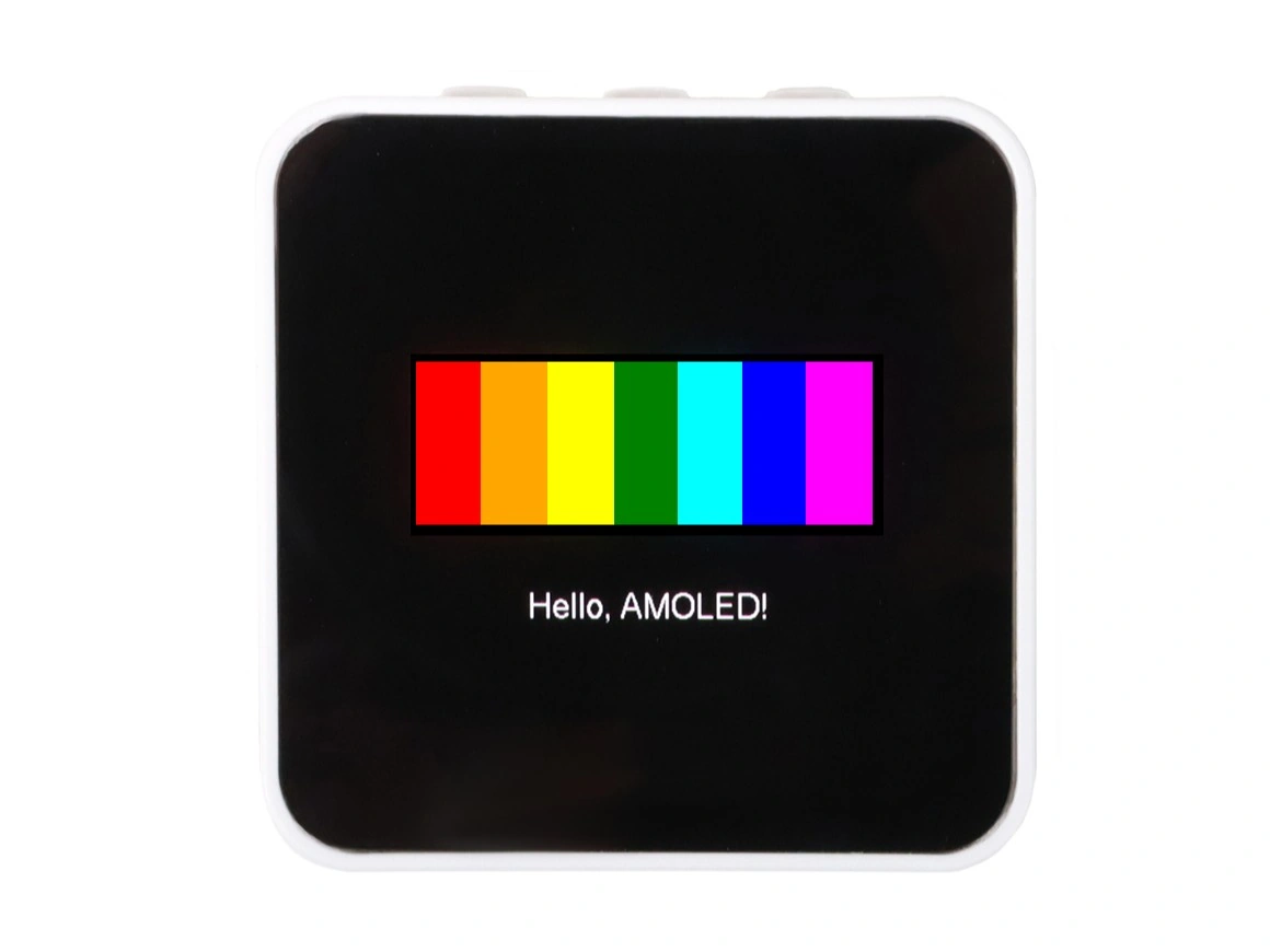
The AMOLED driver code uses exactly the same software layers as the LCD example; only the bus changes to QSPI and the driver class changes to the class for the corresponding IC. After running the following example, the display shows a row of saturated color blocks and a line of text on a pure-black background, which shows how the AMOLED renders black and saturated colors:
#include <U8g2lib.h>
#include <Arduino_GFX_Library.h>

// Pin definitions for ESP32-S3-Touch-AMOLED-2.16
#define LCD_SDIO0 4
#define LCD_SDIO1 5
#define LCD_SDIO2 6
#define LCD_SDIO3 7
#define LCD_SCLK 38
#define LCD_CS 12
#define LCD_RESET 39

#define LCD_WIDTH 480
#define LCD_HEIGHT 480

// Seven 48×120 color blocks centered horizontally.
// Dimensions and the centered starting point are even.
#define SWATCH_COUNT 7
#define SWATCH_WIDTH 48
#define SWATCH_HEIGHT 120
#define SWATCH_X ((LCD_WIDTH - SWATCH_COUNT * SWATCH_WIDTH) / 2)
#define SWATCH_Y 150

// Saturated color blocks on a pure-black background demonstrate AMOLED
// contrast and color performance.
const uint16_t SWATCH_COLORS[SWATCH_COUNT] = {
  RGB565_RED,
  RGB565_ORANGE,
  RGB565_YELLOW,
  RGB565_GREEN,
  RGB565_CYAN,
  RGB565_BLUE,
  RGB565_MAGENTA
};

// Text canvas dimensions.
#define TEXT_CANVAS_WIDTH 200
#define TEXT_CANVAS_HEIGHT 40

// Center the text canvas horizontally below the color blocks.
#define TEXT_CANVAS_X ((LCD_WIDTH - TEXT_CANVAS_WIDTH) / 2)
#define TEXT_CANVAS_Y (SWATCH_Y + SWATCH_HEIGHT + 40)

// 1. QSPI bus: one clock and four data lines.
Arduino_DataBus *bus = new Arduino_ESP32QSPI(
  LCD_CS, LCD_SCLK, LCD_SDIO0, LCD_SDIO1, LCD_SDIO2, LCD_SDIO3);

// 2. CO5300 controller at 480×480.
Arduino_CO5300 *gfx = new Arduino_CO5300(
  bus, LCD_RESET, 0, LCD_WIDTH, LCD_HEIGHT,
  0, 0, 0, 0);

// 3. Local RAM canvas positioned below the color blocks.
Arduino_Canvas *textCanvas = new Arduino_Canvas(
  TEXT_CANVAS_WIDTH, TEXT_CANVAS_HEIGHT, gfx,
  TEXT_CANVAS_X, TEXT_CANVAS_Y);

void setup() {
  if (!gfx->begin()) {
    while (true) {
      delay(1000);
    }
  }

  // Set the display orientation through MADCTL. The library default may not
  // match the panel, so use 0xA0 as in the official example.
  bus->writeC8D8(0x36, 0xA0);

  gfx->fillScreen(RGB565_BLACK);

  // Brightness is a controller command from 0 to 255.
  gfx->setBrightness(255);

  // Draw the color blocks directly; large solid fills do not need a canvas.
  // Keep the rectangles even-aligned for this CO5300 and Arduino_GFX combination.
  for (int i = 0; i < SWATCH_COUNT; i++) {
    gfx->fillRect(
      SWATCH_X + i * SWATCH_WIDTH,
      SWATCH_Y,
      SWATCH_WIDTH,
      SWATCH_HEIGHT,
      SWATCH_COLORS[i]);
  }

  // Allocate the canvas without initializing the display again.
  if (!textCanvas->begin(GFX_SKIP_OUTPUT_BEGIN)) {
    while (true) {
      delay(1000);
    }
  }

  // Draw with the U8g2 Helvetica Regular 18 font in the RAM canvas.
  textCanvas->fillScreen(RGB565_BLACK);
  textCanvas->setFont(u8g2_font_helvR18_tr);
  textCanvas->setTextSize(1);
  textCanvas->setTextColor(RGB565_WHITE);
  textCanvas->setCursor(13, 30);
  textCanvas->print("Hello, AMOLED!");

  // Transfer the complete 200×40 canvas in one operation.
  textCanvas->flush();
}

void loop() {
}
Compared with the LCD example, Arduino_ESP32SPI becomes Arduino_ESP32QSPI, the driver becomes Arduino_CO5300, and backlight GPIO control becomes setBrightness(). u8g2 supplies only font data; Arduino_GFX still drives the panel. Keep setTextSize(1) because u8g2_font_helvR18_tr is already an 18-pixel font.
gfx->begin() uses the Arduino_GFX default 40 MHz QSPI clock. A target such as gfx->begin(80000000) can be tested when more bandwidth is required, but use only a frequency proven stable on the actual hardware.
The solid color blocks are drawn directly. Text is composed in a 200×40 Arduino_Canvas and transferred with one flush(). With this CO5300 and Arduino_GFX combination, compose fine details in a canvas and transfer an aligned rectangle. Direct single-pixel and one-pixel-wide operations can be clipped or omitted, as documented in Arduino_GFX issue #780.
The RGB565 canvas occupies only 200 × 40 × 2 = 16000 bytes and does not require PSRAM. To display more content, adjust the canvas size and output coordinates to match the content. See the Arduino_GFX Canvas Class reference for other canvas formats.
With CO5300 and Arduino_GFX on this board, the starting coordinates, width, and height of each update window must all be even. Arduino_CO5300::writeAddrWindow() writes CASET and PASET without rounding. Odd coordinates or dimensions can be clipped, shifted, or ignored. The official LVGL callback also aligns update regions to even boundaries.
- Draw
fillRectdirectly only with even starting coordinates and dimensions. - Compose circles, diagonal lines, text, and transparent bitmaps in a RAM canvas or framebuffer, then transfer one even-aligned rectangle.
Arduino_CO5300::setRotation() changes MADCTL mirror bits but does not transpose pixels for a 90° or 270° rotation. Handle a portrait/landscape transpose in the application or GUI framework.
4.4 Run the Official Examples
The official Arduino examples are in examples/arduino. Run the examples as needed:
- Basic graphics and random text: Verifies basic display operation.
- ASCII character table: Prints an ASCII character table by row and column, verifying coordinates and display orientation.
- LVGL with AXP2101 power information: Verifies the PMU (Power Management Unit) and basic LVGL output.
- LVGL with QMI8658: Displays live IMU acceleration curves.
- LVGL widgets: Includes touch-controller input—see Touch Input for the touch principle—and automatic screen rotation based on IMU orientation. It provides a reference for a dark-background UI.
4.5 Troubleshooting
| Symptom | Likely cause | Corrective action |
|---|---|---|
| Code compiles but display remains off | Wrong pins or driver class | Check LCD_RESET, LCD_CS, and the product pin tables |
| Allocation failure or LVGL crash | Draw buffers too large or PSRAM disabled | Reduce the buffers or enable OPI PSRAM |
| Brightness remains zero | Brightness command omitted | Call setBrightness() after initialization |
u8g2 text missing at setTextSize(1) | The direct CO5300 drawing path cannot reliably display single pixels and one-pixel-wide elements (Arduino_GFX issue #780) | Draw into Arduino_Canvas, then call flush() |
| Circle or diagonal edge is filled or missing | Odd update-window coordinate or dimension | Use even rectangles and compose nonrectangular graphics in a canvas |
| Persistent image after a fixed UI | Burn-in | Use a dark UI, move bright elements, and dim or turn off the display when idle |