E-Paper
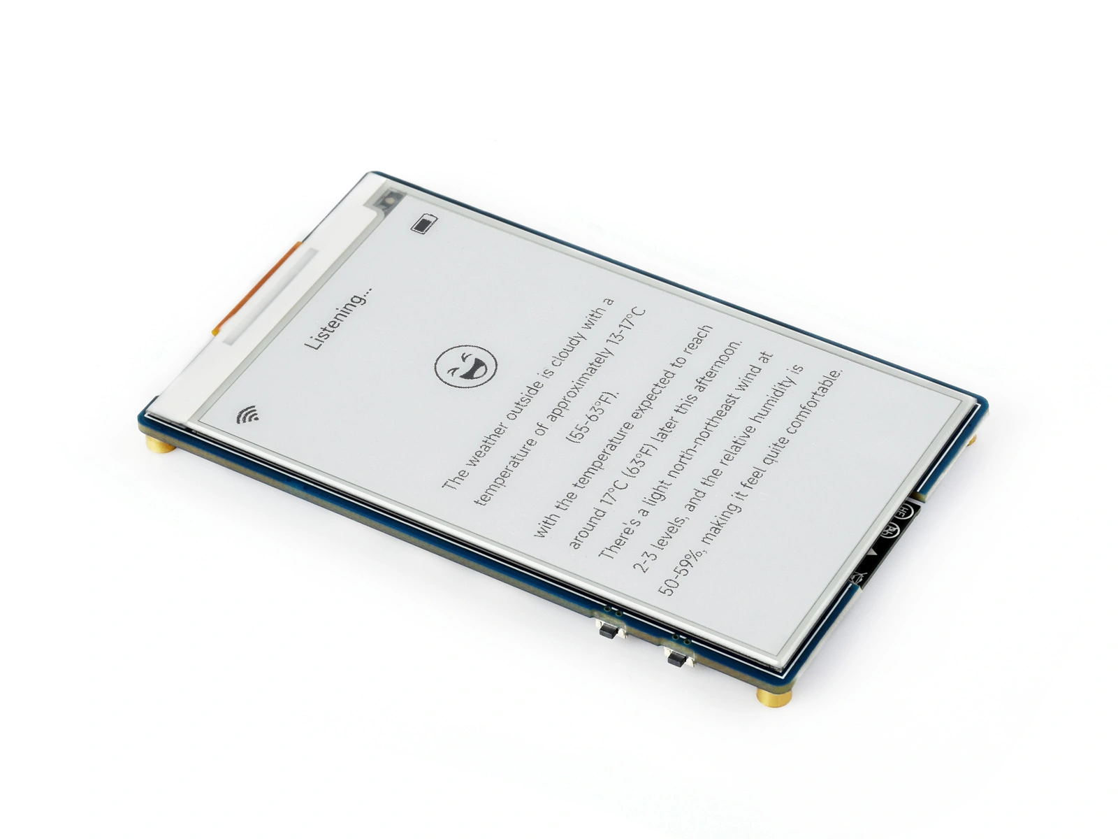
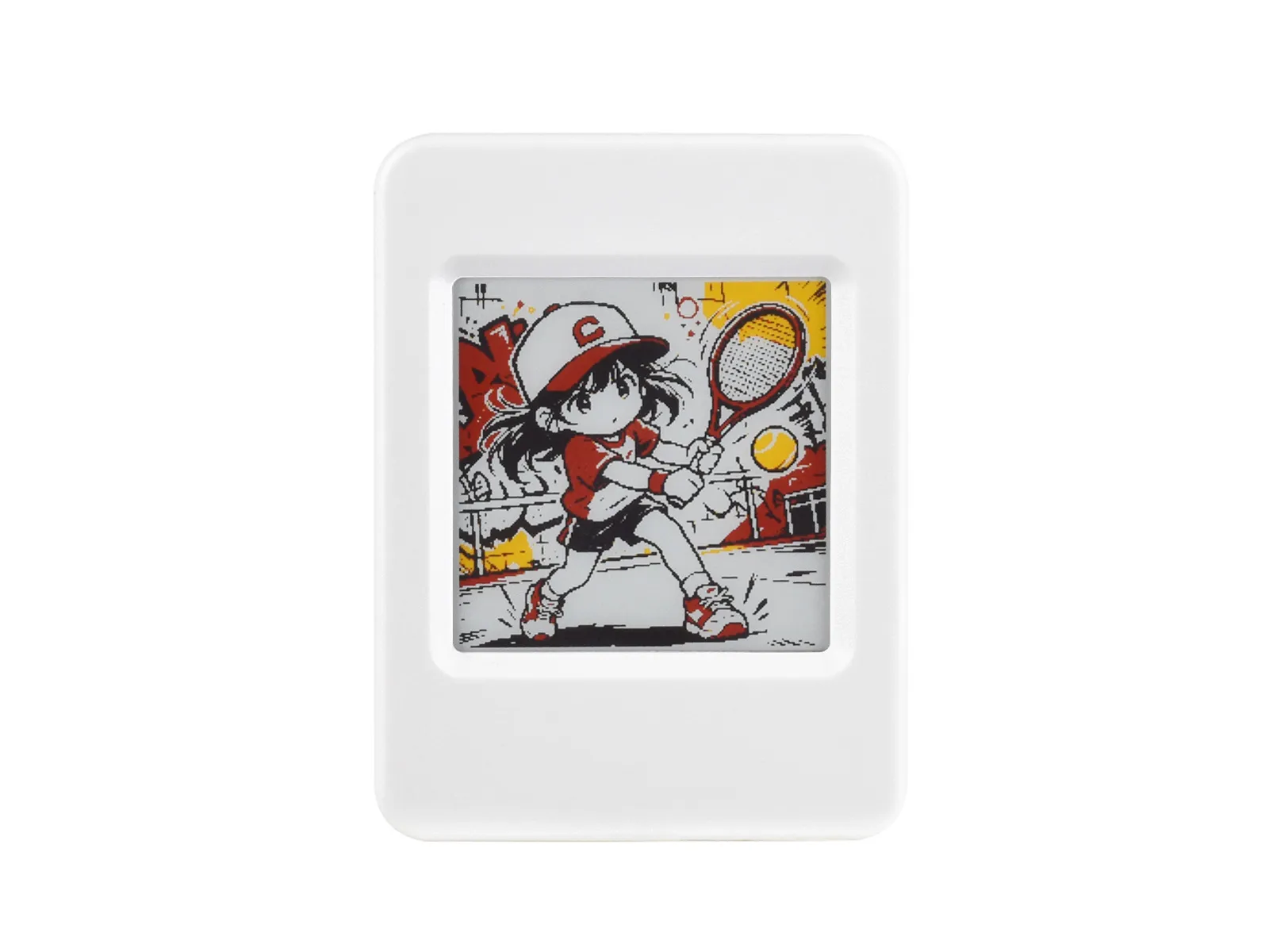
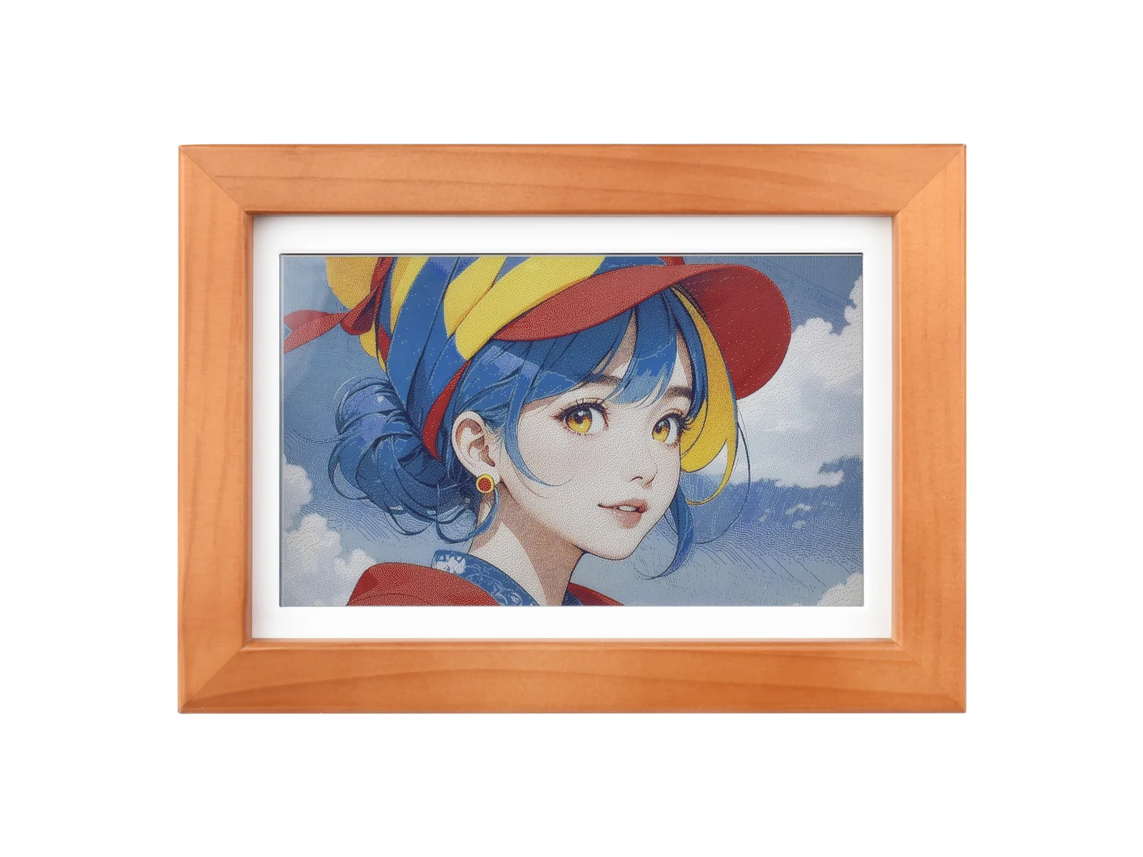
E-Paper (electronic paper, also commonly called an e-ink display) differs significantly from other display technologies: it retains the image even when power is removed and consumes power only while refreshing. Its paper-like appearance and sunlight readability make it suitable for applications in which the image remains unchanged for long periods, such as electronic shelf labels, electronic calendars, and e-readers. The tradeoff is that refreshes take seconds, so E-Paper is not suitable for animation.
This chapter explains how E-Paper forms an image, with particular emphasis on its distinctive full-refresh and partial-refresh mechanisms and the associated ghosting. It then shows how to drive Waveshare E-Paper displays with an ESP32.
1. Display Principle
E-Paper is based on electrophoresis. Consider the most common black-and-white display:

- The display layer is a microcapsule film: countless microcapsules (or microcups) are fixed in a binder and sandwiched between upper and lower electrodes. Each capsule contains suspended negatively charged black particles and positively charged white particles.
- When an electric field is applied between the upper and lower electrodes, the capsules themselves do not move. Only the particles inside them migrate toward opposite electrodes: when the white particles rise to the surface, that area appears white; when the black particles rise, it appears black.
- Once the particles are in position, they remain there after the electric field is removed. This is the bistable characteristic of E-Paper: maintaining an image requires no power, and the content remains visible after power is disconnected.
E-Paper is also a reflective display: it forms an image by reflecting ambient light and has no backlight. The stronger the ambient light, the clearer the image. In darkness it requires external illumination; the front light in an e-reader is an added illumination layer for exactly this purpose.
Color E-Paper extends this principle:
- Three-color displays (black/white/red or black/white/yellow): A third type of charged particle is added to each capsule. The drive waveform is more complex, and refresh time increases significantly.
- Full-color displays: Technologies such as ACeP and Spectra 6 produce color by precisely driving several types of colored particles. The panel can display only a small set of native colors (Spectra 6, for example, provides black, white, red, yellow, green, and blue). A dithering algorithm converts other colors in a photo into spatial mixtures of native-color pixels, which look grainy at close range. These displays refresh even more slowly and have lower color saturation than LCDs, making them suitable for static content such as posters and photo frames—for example, the Spectra 6-based Waveshare ESP32-S3-PhotoPainter.
2. Features and Limitations
Advantages:
- Zero power for a static image: Power is consumed only during a refresh. Keeping an image on screen consumes no power, and the image is not lost when power is removed. Devices such as electronic shelf labels that update only once every few days can run for years on a coin cell.
- Paper-like appearance: Reflective imaging produces no flicker and does not shine light directly into the viewer's eyes, making long reading sessions comfortable.
- Clearly readable in sunlight, with a viewing angle close to 180°.
Limitations:
- Slow refresh: A full refresh takes approximately 2–4 seconds on a black-and-white display and can take 10–30 seconds on displays with three or more colors. The screen flashes several times during the refresh.
- Ghosting: After a fast refresh (partial refresh), a faint trace of the previous image may remain and must be cleared periodically with a full refresh.
- Reduced low-temperature performance: Electrophoretic particles move more slowly at low temperatures. The lower operating-temperature limit of most displays is around 0°C; check the specifications before outdoor winter use.
- Finite refresh life: The number of refresh cycles is limited. Low-frequency updates are not a problem, but the display is unsuitable for frequently refreshed content such as animation or video. See the panel specifications for the exact limits.
E-paper is often used for close-range reading, where text and images dominate; pixel density (PPI, Pixels Per Inch) affects display clarity. In the examples in this chapter, both the 3.97-inch and 7.3-inch displays have a resolution of 800×480, but their pixel densities are approximately 235 PPI and 128 PPI, respectively. When text with the same physical height is displayed, the 7.3-inch display uses fewer pixels, so the stroke edges are more likely to appear jagged.
Both are reflective, low-power displays. Choose E-Paper when the image is largely static and standby time is the priority. Choose RLCD when the content must update in real time, such as a clock's second hand or live data.
3. Refresh Mechanisms: Full and Partial Refresh
The refresh mechanism is the most significant difference between E-Paper and other displays, and it is also the source of most issues encountered in use.
The image data sent by the host controller specifies only the target color of each pixel—for a black-and-white display, whether that pixel should ultimately appear black or white. However, electrophoretic particles need time to migrate through the fluid and cannot change state quickly with a single voltage transition as an LCD pixel can. The driver IC must apply a sequence of voltage pulses with different polarities and durations according to a multi-stage drive waveform to move the particles reliably to their target positions. These waveform parameters are stored in the driver IC as a LUT (look-up table) or written by the driver library during initialization. Different waveforms produce different refresh quality and speed, resulting in two refresh modes:

-
Full refresh: Before writing the new image, the driver moves the entire display back and forth between black and white several times—seen as full-screen flashing—to reset all particles thoroughly. This is slow, but it clears ghosting completely and provides the best image quality. Some driver ICs also provide a fast full refresh, which shortens the waveform and makes the entire screen flash only once. The tradeoff is a less complete particle reset and weaker ghost-clearing performance than a standard full refresh.
-
Partial refresh: Only changed pixels in a specified area are driven to their target states, with no full-screen flashing. On black-and-white displays that support fast partial refresh, the update can take less than one second, making it suitable for small areas such as clock digits or sensor readings. However, the shorter waveform cannot move every particle fully to a stable endpoint at either electrode; some particles stop in intermediate states. After repeated partial refreshes, this error accumulates and produces ghosting. A full refresh is required to drive the particles back and forth and return them to the two endpoints. Check the product documentation to determine whether a panel supports fast partial refresh. Some panels allow a partial window to be configured but still refresh at nearly the same speed and with nearly the same behavior as a full refresh.
At the level of an individual capsule, ghosting can be understood as particles failing to return fully to either electrode:

A general strategy for practical use is:
- Perform one full refresh after power-up to establish a clean baseline image.
- Use partial refresh for frequently updated local areas.
- Perform a full refresh after several partial refreshes (typically every 5–10 updates) or at a regular interval (such as once per hour) to clear accumulated ghosting.
- During a refresh, the driver IC indicates its busy state through the BUSY pin. The program must wait until BUSY is released before starting another operation; the refresh must not be interrupted.
- Do not refresh an E-Paper display continuously at an excessively high rate, as this accelerates display aging. For displays with three or more colors, keep the interval between refreshes at or above the minimum specified on the official product page.
- Before storing a device for an extended period, refresh the screen to white to avoid leaving the same image displayed long enough to create persistent ghosting.
- Do not disconnect power during a refresh. The image may be left in an intermediate state and require a full refresh to recover.
4. Common Driver ICs and Interfaces
E-Paper displays commonly use SPI. DIN carries data, CLK supplies the clock, CS selects the device, DC distinguishes commands from data, and RST resets the driver IC. Compared with a typical SPI display, E-Paper adds a BUSY signal, which is output by the driver IC and read by the host controller to indicate whether a refresh has finished. Common driver ICs include the Solomon Systech SSD168x series and the UltraChip UC81xx series. See the corresponding product page for the IC used by each Waveshare display size.
The E-Paper frame-buffer format depends on the number of colors:
- Black-and-white displays are typically stored at 1 bpp (1 bit per pixel; see Color Depth).
- Three-color displays typically use two 1 bpp frame-buffer planes: one records the black-and-white regions, and the other records the red or yellow regions.
- Four-color displays can be stored at 2 bpp, with each byte recording four pixels.
For example, one frame for the 200×200 four-color display on the ESP32-S3-ePaper-1.54G occupies 200 × 200 × 2 ÷ 8 = 10000 bytes. SPI provides enough bandwidth to transfer this data. E-Paper refreshes slowly because of the physical process of particle migration, not because of data transfer.
5. Arduino + GxEPD2 Driver Examples
This section uses GxEPD2 to drive black-and-white, four-color, and full-color E-Paper displays. The examples are organized by display color type and use the same drawing interface. In every case, the display class, panel driver class, frame-buffer format, and refresh characteristics must match the specific panel.
5.1 General Preparation
- Follow the Arduino IDE Setup tutorial to install Arduino IDE, then install arduino-esp32.
- In Library Manager, search for and install
GxEPD2. When prompted about dependencies, select the option to install all dependencies. See Installing Arduino Libraries for other installation methods.
The examples in this section were verified with the versions in the following table. Panel support may differ between versions. Before using another version, check the GxEPD2 supported-panel list.
| Package | Version or requirement |
|---|---|
| arduino-esp32 | v3.3.10 for this tutorial; v3.2.0 or later |
| GxEPD2 | v1.6.9 for this tutorial; minimum versions for ESP32-S3-ePaper-3.97, ESP32-S3-ePaper-1.54G, and ESP32-S3-PhotoPainter are v1.6.5, v1.6.6, and v1.5.9 respectively |
| Adafruit GFX Library | v1.12.6 |
Unlike the LCD and OLED libraries described earlier, which primarily select a driver by driver IC, GxEPD2 supports individual E-Paper panel models rather than driver IC models. The initialization parameters, color encoding, and refresh waveform must match the panel. Even if two panels use the same driver IC, that alone does not mean one panel's driver class can be used for the other. When using GxEPD2, identify the panel model first, then select its corresponding driver class.
5.2 Black-and-White Display: ESP32-S3-ePaper-3.97
This example uses the ESP32-S3-ePaper-3.97. The board includes a 3.97-inch, 800×480 black-and-white E-Paper display driven by an SSD1677. The display supports fast partial refresh, which is demonstrated in the second example in this section.
Configure the board options as described in Arduino Project Settings for ESP32-S3-ePaper-3.97. The GxEPD2 version requirement for this panel is listed in General Preparation. The display is connected directly to the ESP32-S3, and its signal pins are fixed as follows:
| Signal | GPIO | Description |
|---|---|---|
| EPD_BUSY | GPIO3 | Refresh busy status |
| EPD_DC | GPIO9 | Command/data selection |
| EPD_CS | GPIO10 | SPI chip select |
| EPD_SCLK | GPIO11 | SPI clock |
| EPD_MOSI | GPIO12 | SPI data |
| EPD_RST | GPIO46 | Reset |
The onboard display requires no external wiring. Unlike the ESP32-S3-ePaper-1.54G, this board has no separate display power-control pin. The display is powered whenever the system is powered, so the code does not need to control a power pin.
Example: Drawing a Static Image with GxEPD2
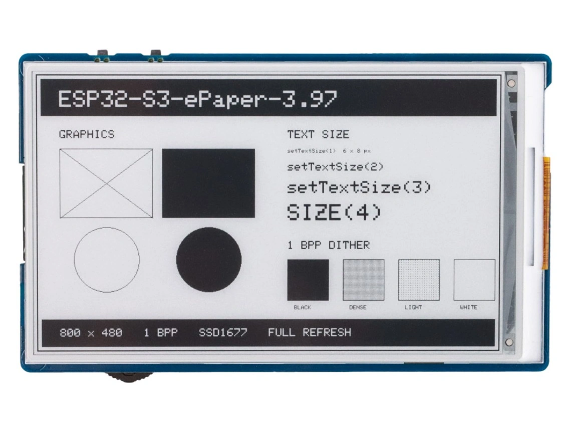
The black-and-white display uses a 1 bpp frame buffer, so one frame occupies 800 × 480 ÷ 8 = 48000 bytes. The ESP32-S3 can hold the complete image in internal RAM. The following example draws a static screen containing geometric shapes, text in four sizes, and a set of halftone-dithered patches.
#include <SPI.h>
#include <GxEPD2_BW.h>

constexpr int EPD_BUSY = 3;
constexpr int EPD_DC = 9;
constexpr int EPD_CS = 10;
constexpr int EPD_SCLK = 11;
constexpr int EPD_MOSI = 12;
constexpr int EPD_RST = 46;

using EpdDriver = GxEPD2_397_GDEM0397T81;
GxEPD2_BW<EpdDriver, EpdDriver::HEIGHT> display(
  EpdDriver(EPD_CS, EPD_DC, EPD_RST, EPD_BUSY));

// Fill a halftone pattern at step intervals to simulate gray with black and white pixels
void fillDither(int x, int y, int w, int h, int step) {
  for (int j = 0; j < h; ++j) {
    for (int i = 0; i < w; ++i) {
      if ((i % step == 0) && (j % step == 0)) {
        display.drawPixel(x + i, y + j, GxEPD_BLACK);
      }
    }
  }
}

void drawStatic() {
  display.fillScreen(GxEPD_WHITE);
  display.setTextWrap(false);

  // Title bar
  display.fillRect(8, 8, 784, 64, GxEPD_BLACK);
  display.setTextColor(GxEPD_WHITE);
  display.setTextSize(4);
  display.setCursor(40, 28);
  display.print("ESP32-S3-ePaper-3.97");

  // Left: geometric shapes
  display.setTextColor(GxEPD_BLACK);
  display.setTextSize(2);
  display.setCursor(40, 96);
  display.print("GRAPHICS");

  display.drawRect(40, 128, 160, 120, GxEPD_BLACK);
  display.fillRect(216, 128, 160, 120, GxEPD_BLACK);
  display.drawCircle(120, 320, 56, GxEPD_BLACK);
  display.fillCircle(296, 320, 56, GxEPD_BLACK);
  display.drawLine(40, 128, 200, 248, GxEPD_BLACK);
  display.drawLine(40, 248, 200, 128, GxEPD_BLACK);

  // Right: different text sizes
  display.setTextSize(2);
  display.setCursor(432, 96);
  display.print("TEXT SIZE");

  display.setTextSize(1);
  display.setCursor(432, 128);
  display.print("setTextSize(1)  6 x 8 px");
  display.setTextSize(2);
  display.setCursor(432, 152);
  display.print("setTextSize(2)");
  display.setTextSize(3);
  display.setCursor(432, 184);
  display.print("setTextSize(3)");
  display.setTextSize(4);
  display.setCursor(432, 224);
  display.print("SIZE(4)");

  // Lower right: 1 bpp provides only black and white; dot density simulates intermediate tones
  display.setTextSize(2);
  display.setCursor(432, 288);
  display.print("1 BPP DITHER");

  const int patchX[] = {432, 528, 624, 720};
  const char *patchLabel[] = {"BLACK", "DENSE", "LIGHT", "WHITE"};
  for (int i = 0; i < 4; ++i) {
    display.drawRect(patchX[i], 320, 72, 72, GxEPD_BLACK);
    display.setTextSize(1);
    display.setCursor(patchX[i] + 12, 400);
    display.print(patchLabel[i]);
  }
  display.fillRect(433, 321, 70, 70, GxEPD_BLACK);
  fillDither(529, 321, 70, 70, 2);
  fillDither(625, 321, 70, 70, 4);

  // Bottom bar
  display.fillRect(8, 424, 784, 48, GxEPD_BLACK);
  display.setTextColor(GxEPD_WHITE);
  display.setTextSize(2);
  display.setCursor(40, 440);
  display.print("800 x 480   1 BPP   SSD1677   FULL REFRESH");

  // Draw the outer border last so the color patches do not cover it
  display.drawRect(0, 0, 800, 480, GxEPD_BLACK);
  display.drawRect(1, 1, 798, 478, GxEPD_BLACK);
}

void setup() {
  // Map the hardware SPI bus to the pins used by the onboard display
  SPI.begin(EPD_SCLK, -1, EPD_MOSI, EPD_CS);

  display.init(115200);
  // Use the standard full-refresh waveform to clear all traces of the previous image
  display.epd2.selectFastFullUpdate(false);
  display.setRotation(0);
  display.setFullWindow();

  uint32_t start = millis();
  display.firstPage();
  do {
    drawStatic();
  } while (display.nextPage());

  Serial.printf("full refresh: %lu ms\n", millis() - start);

  display.hibernate();
}

void loop() {
}
GxEPD2_BW is the black-and-white display class, and GxEPD2_397_GDEM0397T81 is the driver class for this panel. Setting the template parameter to EpdDriver::HEIGHT keeps the complete image in memory. setRotation(0) selects the 800×480 landscape orientation, with the coordinate origin at the upper-left corner.
GxEPD2 enables fast full refresh for this panel by default. It is fast, but it can retain a trace of the previous image, so this example calls selectFastFullUpdate(false) to select a standard full refresh and produce a clean image in one pass. See Full Refresh vs. Partial Refresh for a comparison of the three refresh modes. As in the four-color example, you must call SPI.begin(EPD_SCLK, -1, EPD_MOSI, EPD_CS) before display.init(); otherwise, GxEPD2 will not use the board's onboard display pins.
The four patches in the lower-right corner illustrate the capabilities of a 1 bpp display. The panel provides only black and white. fillDither() places black pixels at different intervals so that the patches appear as different shades of gray at normal viewing distance. The same technique is used to display photos on a black-and-white panel by converting a grayscale image into black-and-white halftone dots; the principle is the same as dithering on a full-color display.
Example: Full Refresh vs. Partial Refresh
The following example displays a continuously incrementing counter in the center of the screen. By default, it uses a partial refresh to update the window containing the counter. The last of every 10 updates uses a full refresh instead. The duration of each refresh is printed to the serial port. The program adds no extra delay and increments the counter immediately after each refresh, so the rate at which the counter advances is the refresh rate.
#include <SPI.h>
#include <GxEPD2_BW.h>

constexpr int EPD_BUSY = 3;
constexpr int EPD_DC = 9;
constexpr int EPD_CS = 10;
constexpr int EPD_SCLK = 11;
constexpr int EPD_MOSI = 12;
constexpr int EPD_RST = 46;

using EpdDriver = GxEPD2_397_GDEM0397T81;
GxEPD2_BW<EpdDriver, EpdDriver::HEIGHT> display(
  EpdDriver(EPD_CS, EPD_DC, EPD_RST, EPD_BUSY));

// Partial-refresh window; x and width are multiples of 8
constexpr int WIN_X = 280;
constexpr int WIN_Y = 180;
constexpr int WIN_W = 240;
constexpr int WIN_H = 120;

// Use a full refresh for every 10th update and partial refresh for the other nine
constexpr int UPDATES_PER_FULL = 10;

uint32_t counter = 0;

// Static background, drawn only during a full refresh
void drawFrame() {
  display.fillScreen(GxEPD_WHITE);
  display.setTextWrap(false);

  display.fillRect(8, 8, 784, 56, GxEPD_BLACK);
  display.setTextColor(GxEPD_WHITE);
  display.setTextSize(3);
  display.setCursor(40, 26);
  display.print("FULL vs PARTIAL REFRESH");

  display.setTextColor(GxEPD_BLACK);
  display.setTextSize(2);
  display.setCursor(WIN_X, WIN_Y - 40);
  display.print("UPDATE COUNT");

  // Draw the border outside the partial-refresh window so it is not redrawn
  display.drawRect(
    WIN_X - 8, WIN_Y - 8, WIN_W + 16, WIN_H + 16, GxEPD_BLACK);

  display.setTextSize(2);
  display.setCursor(40, 400);
  display.print("full refresh every 10 updates");

  display.drawRect(0, 0, 800, 480, GxEPD_BLACK);
}

// Counter, drawn during both partial and full refreshes
void drawCounter() {
  display.setTextColor(GxEPD_BLACK);
  display.setTextSize(7);
  display.setCursor(WIN_X + 24, WIN_Y + 32);
  display.print(counter);
}

// Full refresh: redraw the entire screen
uint32_t refreshFull() {
  uint32_t start = millis();
  display.setFullWindow();
  display.firstPage();
  do {
    drawFrame();
    drawCounter();
  } while (display.nextPage());
  return millis() - start;
}

// Partial refresh: redraw only the window containing the counter
uint32_t refreshPartial() {
  uint32_t start = millis();
  display.setPartialWindow(WIN_X, WIN_Y, WIN_W, WIN_H);
  display.firstPage();
  do {
    display.fillScreen(GxEPD_WHITE);
    drawCounter();
  } while (display.nextPage());
  return millis() - start;
}

void setup() {
  SPI.begin(EPD_SCLK, -1, EPD_MOSI, EPD_CS);

  display.init(115200);
  display.setRotation(0);

  // Perform one full refresh after power-up to establish a clean baseline image
  Serial.printf("full    refresh #%lu: %lu ms\n", counter, refreshFull());
}

void loop() {
  // Add no delay, so continuous updates reveal the speed difference between the two modes
  ++counter;

  if (counter % UPDATES_PER_FULL == 0) {
    Serial.printf("full    refresh #%lu: %lu ms\n", counter, refreshFull());
  } else {
    Serial.printf("partial refresh #%lu: %lu ms\n", counter, refreshPartial());
  }
}
The code implements the general strategy described under Refresh Mechanisms:
setFullWindow()andsetPartialWindow(x, y, w, h)determine the mode and area of the current refresh. The partial-refresh window'sxcoordinate and width should be multiples of 8 so that they align with the eight pixels stored in each frame-buffer byte.- During a partial refresh,
fillScreen()affects only the current window. The counter border is therefore drawn outside the window so that it is not refreshed repeatedly. - Partial refresh relies on the previous-frame data retained in the driver IC to calculate changes, so the program first performs a full refresh after power-up to establish a baseline image.
- The last of every 10 updates uses a full refresh and redraws the complete screen. In this example, the partial-refresh area is small and the interval is short, so the default fast full refresh is sufficient to keep the image clean. If ghosting has already become obvious, use a standard full refresh instead.
GxEPD2 enables fast full refresh for this panel by default (useFastFullUpdate is true in the driver class). In testing, the waveform took 1.70 seconds for a fast full refresh and 370 ms for a partial refresh. Including image-data transfer and driver power-up, the total time printed by this example was approximately 2.46 seconds for a full refresh and 420 ms for a partial refresh, making partial refresh about six times faster. display.init(115200) enables GxEPD2 diagnostic output. The _Update_Part and _Update_Full values printed to the serial port are waveform durations in microseconds. Total duration is also affected by the partial-window size and SPI clock.
Call display.epd2.selectFastFullUpdate(false) after display.init() to switch to standard full refresh; its measured waveform duration was 2.10 seconds. The three refresh modes are summarized below:
| Refresh Mode | GxEPD2 Usage | Waveform Duration | Behavior During Refresh | Ghosting |
|---|---|---|---|---|
| Standard full refresh | selectFastFullUpdate(false) + setFullWindow() | 2.10 s | The full screen flashes back and forth several times | Cleared completely |
| Fast full refresh | Default + setFullWindow() | 1.70 s | The full screen flashes once | A trace of the previous image may remain |
| Partial refresh | setPartialWindow() | 370 ms | No flashing; content is replaced directly | Accumulates with each refresh |
The first refresh after power-up performs two full refreshes. When GxEPD2 first writes to display memory, it refreshes the entire screen to white and then refreshes the actual image to establish a clean baseline. As a result, the total duration of #0 shown in the serial output is approximately twice that of later full refreshes (4.52 seconds measured in this example and 5.39 seconds in the first example using standard full refresh). This is normal.
Ghosting visibility depends on the number of accumulated partial refreshes and the area in which the image is inverted. In this example, the digit area is small and a full refresh occurs every 10 updates, so obvious ghosting is usually not visible. When large black-and-white areas are inverted repeatedly, ghosting appears as faint residue around the edges of the inverted region. The default fast full refresh is then insufficient to clear the residue; switch to a standard full refresh so that the back-and-forth drive returns the particles to the two electrodes.
Whether traces of the previous image carry over into the new image depends mainly on the state in which the last refresh left the particles. After a standard full refresh, the particles have been driven to the two electrodes and any accumulated error has been cleared, so subsequent refreshes will not reveal traces of older images. After many partial refreshes, particles remain in intermediate states. If only a fast full refresh is then performed, traces of the previous image remain in the new one, especially across large solid-black or solid-white areas.
Monochrome Pixel Encoding and Display Memory
ESP32-S3-ePaper-3.97 uses 1 bpp (one bit per pixel) image data. Each byte of display memory records eight horizontally adjacent pixels, from the most significant bit to the least significant bit:
| Color | GxEPD2 color constant | Bit value | Description |
|---|---|---|---|
| Black | GxEPD_BLACK | 0 | The drive waveform moves black particles to the surface |
| White | GxEPD_WHITE | 1 | The drive waveform moves white particles to the surface |
One complete frame at 800×480 occupies 800 × 480 ÷ 8 = 48000 bytes, approximately 46.9 KB, which fits entirely in the ESP32-S3 internal SRAM. For a partial refresh, use multiples of 8 for the window's starting x coordinate and width so that the window stays aligned with display-memory byte boundaries.
Using the Waveshare Official Library
The Waveshare official example includes the EPD_3in97 driver, the GUI_Paint graphics library, fonts, and image data. The basic call sequence is:
DEV_Module_Init();
EPD_3IN97_Init();
EPD_3IN97_Display_Base(image);     // Full refresh; also writes the baseline frame required for partial refresh
EPD_3IN97_Display_Partial(image, x_start, y_start, x_end, y_end);
EPD_3IN97_Sleep();
EPD_3IN97_Init_Fast() and EPD_3IN97_Display_Fast() select the fast full-refresh waveform. The driver also provides EPD_3IN97_Init_4GRAY() and EPD_3IN97_Display_4Gray(), which use a multi-stage waveform to display four grayscale levels on the same panel, at the cost of a longer refresh time and no partial-refresh support. See the ESP32-S3-ePaper-3.97 official example for the complete program, and the ESP32-S3-ePaper-3.97 Arduino tutorial for development-environment and upload settings.
Refresh and Sleep
display.hibernate() places the display driver in deep sleep for the lowest power consumption, but the previous-frame data in the driver IC then becomes invalid. To refresh after hibernation, reinitialize the driver and perform a full refresh before resuming partial refresh. Applications that require ongoing partial refreshes, such as clocks or sensor readouts, should keep the driver powered and call hibernate() only when no update will be needed for an extended period.
- Content outside the partial-refresh window is not updated. Use a full refresh when changing the screen layout.
- This example refreshes continuously to demonstrate the speed difference. In a real product, control the refresh interval according to the required update rate.
- Before an extended period of non-use, refresh the display to white and then call
hibernate().
5.3 Four-Color Display: ESP32-S3-ePaper-1.54G
This example uses the ESP32-S3-ePaper-1.54G. The board includes a 1.54-inch, 200×200 four-color E-Paper display that can show black, white, yellow, and red. The model with the G suffix is the four-color version; the ESP32-S3-ePaper-1.54 without G is the black-and-white version. The two versions use different drivers and have different refresh times.
Configure the board options as described in Arduino Project Settings for ESP32-S3-ePaper-1.54G. The GxEPD2 version requirement for this panel is listed in General Preparation. The display is connected directly to the ESP32-S3, and its signal and power-control pins are fixed as follows:
| Signal | GPIO | Description |
|---|---|---|
| EPD_PWR | GPIO6 | Display power control; low enables power and high disables it |
| EPD_BUSY | GPIO8 | Refresh busy status |
| EPD_RST | GPIO9 | Reset |
| EPD_DC | GPIO10 | Command/data selection |
| EPD_CS | GPIO11 | SPI chip select |
| EPD_SCLK | GPIO12 | SPI clock |
| EPD_MOSI | GPIO13 | SPI data |
The onboard display requires no external wiring. EPD_PWR controls display power. After a refresh is complete and the display has entered sleep, drive it high to turn off display power.
Example: Drawing a Four-Color Price Tag with GxEPD2
GxEPD2 uses the Adafruit GFX drawing API, so functions such as fillRect(), fillCircle(), drawRect(), and print() can be combined to construct an image. The following example turns the display into an electronic price tag while demonstrating all four native colors—red, yellow, black, and white—along with different text sizes and geometric shapes.
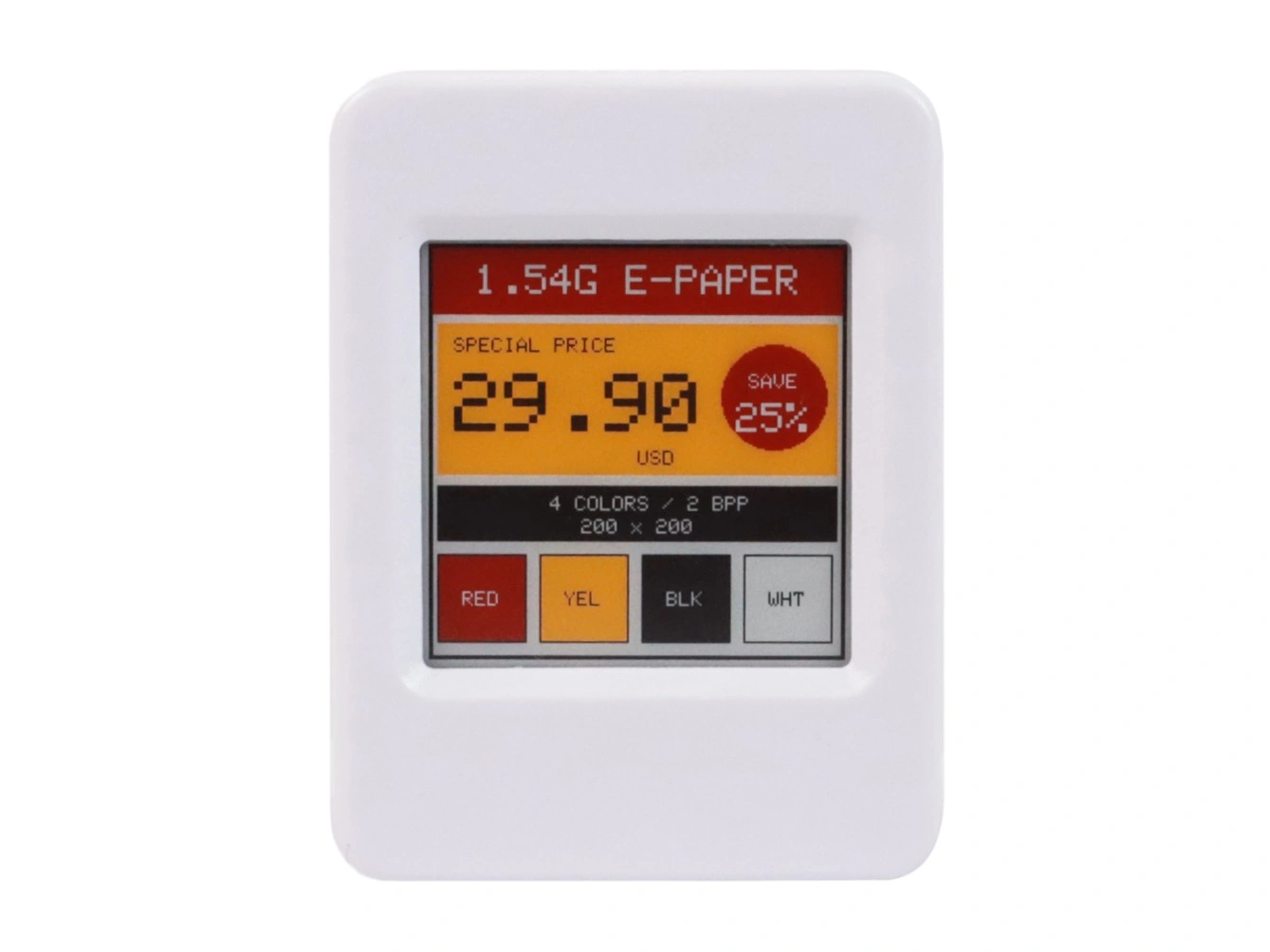
#include <SPI.h>
#include <GxEPD2_4C.h>

constexpr int EPD_PWR = 6;
constexpr int EPD_BUSY = 8;
constexpr int EPD_RST = 9;
constexpr int EPD_DC = 10;
constexpr int EPD_CS = 11;
constexpr int EPD_SCLK = 12;
constexpr int EPD_MOSI = 13;

using EpdDriver = GxEPD2_154c_GDEM0154F51H;
GxEPD2_4C<EpdDriver, EpdDriver::HEIGHT> display(
  EpdDriver(EPD_CS, EPD_DC, EPD_RST, EPD_BUSY));

void drawShowcase() {
  display.fillScreen(GxEPD_WHITE);
  display.setTextWrap(false);

  // Red title bar
  display.fillRect(2, 2, 196, 32, GxEPD_RED);
  display.setTextColor(GxEPD_WHITE);
  display.setTextSize(2);
  display.setCursor(22, 10);
  display.print("1.54G E-PAPER");

  // Yellow price-tag body
  display.fillRect(4, 38, 192, 73, GxEPD_YELLOW);
  display.setTextColor(GxEPD_BLACK);
  display.setTextSize(1);
  display.setCursor(12, 45);
  display.print("SPECIAL PRICE");

  display.setTextSize(4);
  display.setCursor(12, 62);
  display.print("29.90");

  display.setTextSize(1);
  display.setCursor(100, 99);
  display.print("USD");

  // Red discount badge
  display.fillCircle(165, 73, 25, GxEPD_RED);
  display.setTextColor(GxEPD_WHITE);
  display.setTextSize(1);
  display.setCursor(153, 62);
  display.print("SAVE");
  display.setTextSize(2);
  display.setCursor(147, 76);
  display.print("25%");

  // Black specification bar
  display.fillRect(4, 116, 192, 27, GxEPD_BLACK);
  display.setTextColor(GxEPD_WHITE);
  display.setTextSize(1);
  display.setCursor(58, 121);
  display.print("4 COLORS / 2 BPP");
  display.setCursor(73, 132);
  display.print("200 x 200");

  // Four native colors
  const int swatchY = 149;
  const int swatchW = 43;
  const int swatchH = 43;
  const int swatchX[] = {4, 53, 102, 151};
  const uint16_t swatchColor[] = {
    GxEPD_RED, GxEPD_YELLOW, GxEPD_BLACK, GxEPD_WHITE
  };
  const uint16_t labelColor[] = {
    GxEPD_WHITE, GxEPD_BLACK, GxEPD_WHITE, GxEPD_BLACK
  };
  const char *label[] = {"RED", "YEL", "BLK", "WHT"};

  display.setTextSize(1);
  for (int i = 0; i < 4; ++i) {
    display.fillRect(
      swatchX[i], swatchY, swatchW, swatchH, swatchColor[i]);
    display.drawRect(
      swatchX[i], swatchY, swatchW, swatchH, GxEPD_BLACK);
    display.setTextColor(labelColor[i]);
    display.setCursor(swatchX[i] + 12, swatchY + 18);
    display.print(label[i]);
  }

  // Draw the outer border last so the color patches do not cover it
  display.drawRect(0, 0, 200, 200, GxEPD_BLACK);
  display.drawRect(1, 1, 198, 198, GxEPD_BLACK);
}

void setup() {
  pinMode(EPD_PWR, OUTPUT);
  digitalWrite(EPD_PWR, LOW);  // Turn on display power
  delay(10);

  // Map the hardware SPI bus to the pins used by the onboard display
  SPI.begin(EPD_SCLK, -1, EPD_MOSI, EPD_CS);

  display.init(115200);
  display.setRotation(0);
  display.setFullWindow();

  display.firstPage();
  do {
    drawShowcase();
  } while (display.nextPage());

  display.hibernate();
  digitalWrite(EPD_PWR, HIGH);  // Turn off display power
}

void loop() {
}
GxEPD2_4C is the four-color display class, and GxEPD2_154c_GDEM0154F51H is the driver class for this panel. A complete frame buffer occupies only 10000 bytes, so the template parameter is set to EpdDriver::HEIGHT to keep the complete image in memory. firstPage() and nextPage() form the GxEPD2 paged-drawing loop. With a full frame buffer, the loop runs only once, but retaining this form also allows the code to be changed to use a paged buffer later.
The ESP32-S3 can route SPI signals to different GPIOs. You must call SPI.begin(EPD_SCLK, -1, EPD_MOSI, EPD_CS) before display.init(); otherwise, GxEPD2 will not use the board's onboard display pins. GPIO6 is the display power-control pin and is not managed by GxEPD2. Drive it low before initialization and high after display.hibernate().
Four-Color Pixel Encoding and Display Memory
The ESP32-S3-ePaper-1.54G uses 2 bpp image data. Each byte stores four horizontally adjacent pixels in order from the most significant bits to the least significant bits:
| Color | GxEPD2 color constant | Encoding |
|---|---|---|
| Black | GxEPD_BLACK | 00 |
| White | GxEPD_WHITE | 01 |
| Yellow | GxEPD_YELLOW | 10 |
| Red | GxEPD_RED | 11 |
For example, if four consecutive pixels are black, white, yellow, and red, their data is 00 01 10 11, or 0x1B. One frame at 200×200 occupies 200 × 200 × 2 ÷ 8 = 10000 bytes, approximately 9.8 KB, so the complete image fits in internal SRAM. GxEPD2 handles pixel packing internally. When using the Adafruit GFX drawing API, pass the corresponding color constant directly.
Using the Waveshare Official Library
The Waveshare official example includes the EPD_1in54g driver, the GUI_Paint graphics library, fonts, and image data. It is useful for checking hardware operation, examining the low-level initialization sequence, or continuing development within an existing Waveshare example project. The basic call sequence is:
DEV_Module_Init();
EPD_1IN54G_Init_Fast();
EPD_1IN54G_Display(image);
EPD_1IN54G_Sleep();
Keep the complete project directory containing the .ino, driver, and resource files. See the ESP32-S3-ePaper-1.54G official example for the complete program, and the ESP32-S3-ePaper-1.54G Arduino tutorial for development-environment and upload settings.
Refresh and Sleep
This display takes approximately 20 seconds for a standard full refresh and approximately 15 seconds for a fast full refresh. The GxEPD2 driver allows a partial window to be configured, but this panel does not support the fast partial refresh commonly available on black-and-white displays (see Full Refresh vs. Partial Refresh), so it is unsuitable for frequently updated dynamic content. In the Waveshare official library, EPD_1IN54G_Init_Fast() selects the fast waveform, but EPD_1IN54G_Display() still refreshes the complete screen.
- Leave at least 180 seconds between refreshes. Frequent refreshes may affect image quality and display life.
- After displaying the image, place the display driver in deep sleep: call
display.hibernate()with GxEPD2 orEPD_1IN54G_Sleep()with the Waveshare official library. Then driveEPD_PWR(GPIO6) high to turn off display power. - The display no longer processes image data after entering sleep. Before the next refresh, drive
EPD_PWRlow again and reinitialize the display driver.
5.4 Full-Color Display: ESP32-S3-PhotoPainter
This example uses the ESP32-S3-PhotoPainter. It includes a 7.3-inch, 800×480 E Ink Spectra 6 display that can show six native colors directly: black, white, green, blue, red, and yellow. Other colors must be produced through dithering; see Displaying Mixed Colors with Dithering.
This display uses the GxEPD2 GxEPD2_730c_GDEP073E01 panel driver class and requires GxEPD2_7C.h. The GxEPD2 version requirement for this panel is listed in General Preparation.
In Arduino IDE Library Manager, search for and install XPowersLib. This library configures the onboard AXP2101 power-management IC so that ALDO4 supplies 3.3 V to the E-Paper display.
The ESP32-S3-PhotoPainter's EPD_VCC is connected to ALDO4 on the AXP2101. Before using the display, set this output to 3.3 V and enable it.
The display and AXP2101 are connected directly to the ESP32-S3, so no external wiring is required. In Arduino IDE, select Tools > Board > esp32 > ESP32S3 Dev Module, then configure the following options:
- Flash Size:
16MB (128Mb) - PSRAM:
OPI PSRAM - USB CDC On Boot:
Enabled
The onboard interface pins are fixed as follows:
| Signal | GPIO | Description |
|---|---|---|
| EPD_DC | GPIO8 | Command/data selection |
| EPD_CS | GPIO9 | SPI chip select |
| EPD_SCLK | GPIO10 | SPI clock |
| EPD_MOSI | GPIO11 | SPI data |
| EPD_RST | GPIO12 | Reset |
| EPD_BUSY | GPIO13 | Refresh busy status |
| PMU_SDA | GPIO47 | AXP2101 I2C data |
| PMU_SCL | GPIO48 | AXP2101 I2C clock |
Example: Drawing a Six-Color Concentric-Circle Composition with GxEPD2
The following example uses only the GxEPD2 and Adafruit GFX graphics interfaces; it does not read an SD card or external image. The main image is a 5 × 3 array of concentric circles. Each cell consists of a background color and three concentric circles. A table defines the color combinations, and nested loops generate the image. A color chart at the bottom lists the six native colors. This type of solid-color composition requires no dithering and makes it easy to compare the contrast of different color combinations directly on the display.
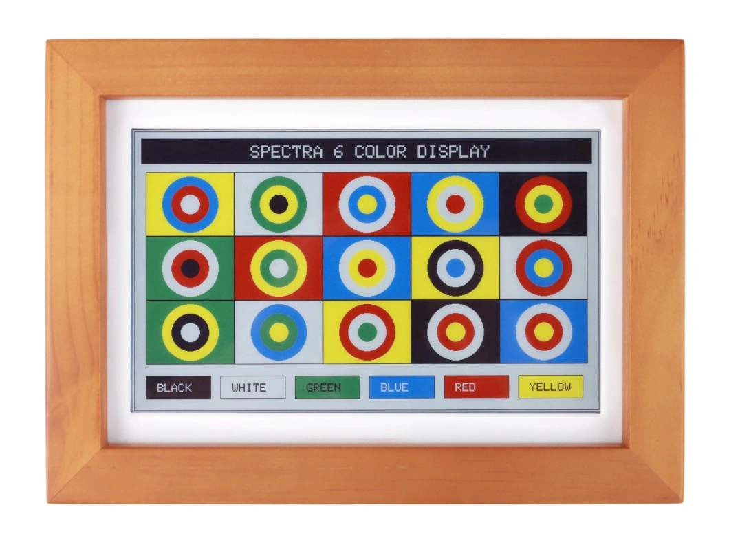
#include <SPI.h>
#include <Wire.h>

#define XPOWERS_CHIP_AXP2101
#include <XPowersLib.h>
#include <GxEPD2_7C.h>

constexpr int PMU_SDA = 47;
constexpr int PMU_SCL = 48;

constexpr int EPD_DC = 8;
constexpr int EPD_CS = 9;
constexpr int EPD_SCLK = 10;
constexpr int EPD_MOSI = 11;
constexpr int EPD_RST = 12;
constexpr int EPD_BUSY = 13;

using EpdDriver = GxEPD2_730c_GDEP073E01;

// Buffer 40 lines at a time: 800 × 40 × 4 ÷ 8 = 16000 bytes
GxEPD2_7C<EpdDriver, 40> display(
  EpdDriver(EPD_CS, EPD_DC, EPD_RST, EPD_BUSY));

XPowersPMU power;

bool initEpaperPower() {
  if (!power.begin(
        Wire, AXP2101_SLAVE_ADDRESS, PMU_SDA, PMU_SCL)) {
    Serial.println("AXP2101 initialization failed.");
    return false;
  }

  // Set and enable the 3.3 V supply for the E-Paper display
  if (!power.setALDO4Voltage(3300)) {
    Serial.println("Failed to set ALDO4 to 3.3 V.");
    return false;
  }

  if (!power.enableALDO4()) {
    Serial.println("Failed to enable ALDO4.");
    return false;
  }

  delay(10);
  return true;
}

void drawPalette() {
  const uint16_t colors[] = {
    GxEPD_BLACK, GxEPD_WHITE, GxEPD_GREEN,
    GxEPD_BLUE, GxEPD_RED, GxEPD_YELLOW
  };
  const uint16_t labelColors[] = {
    GxEPD_WHITE, GxEPD_BLACK, GxEPD_BLACK,
    GxEPD_WHITE, GxEPD_WHITE, GxEPD_BLACK
  };
  const char *labels[] = {
    "BLACK", "WHITE", "GREEN", "BLUE", "RED", "YELLOW"
  };

  display.setTextSize(2);
  for (int i = 0; i < 6; ++i) {
    const int16_t x = 20 + i * 128;
    display.fillRect(x, 420, 112, 40, colors[i]);
    display.drawRect(x, 420, 112, 40, GxEPD_BLACK);
    display.setTextColor(labelColors[i]);
    display.setCursor(x + 20, 433);
    display.print(labels[i]);
  }
}

void drawCirclesGrid() {
  // Color combination for each cell: background, outer ring, middle ring, inner circle
  const uint16_t cellColors[15][4] = {
    {GxEPD_YELLOW, GxEPD_BLUE, GxEPD_RED, GxEPD_WHITE},
    {GxEPD_WHITE, GxEPD_GREEN, GxEPD_YELLOW, GxEPD_BLACK},
    {GxEPD_RED, GxEPD_WHITE, GxEPD_BLUE, GxEPD_YELLOW},
    {GxEPD_BLUE, GxEPD_YELLOW, GxEPD_WHITE, GxEPD_RED},
    {GxEPD_BLACK, GxEPD_RED, GxEPD_YELLOW, GxEPD_GREEN},
    {GxEPD_GREEN, GxEPD_WHITE, GxEPD_RED, GxEPD_BLACK},
    {GxEPD_RED, GxEPD_YELLOW, GxEPD_GREEN, GxEPD_WHITE},
    {GxEPD_BLUE, GxEPD_WHITE, GxEPD_YELLOW, GxEPD_RED},
    {GxEPD_YELLOW, GxEPD_BLACK, GxEPD_WHITE, GxEPD_BLUE},
    {GxEPD_WHITE, GxEPD_RED, GxEPD_BLUE, GxEPD_YELLOW},
    {GxEPD_GREEN, GxEPD_YELLOW, GxEPD_BLACK, GxEPD_WHITE},
    {GxEPD_WHITE, GxEPD_BLUE, GxEPD_GREEN, GxEPD_YELLOW},
    {GxEPD_YELLOW, GxEPD_RED, GxEPD_WHITE, GxEPD_GREEN},
    {GxEPD_BLACK, GxEPD_WHITE, GxEPD_RED, GxEPD_YELLOW},
    {GxEPD_BLUE, GxEPD_WHITE, GxEPD_RED, GxEPD_YELLOW},
  };

  const int16_t originX = 20;
  const int16_t originY = 70;
  const int16_t cellW = 152;
  const int16_t cellH = 110;
  const int16_t radius[] = {48, 32, 16};

  for (int row = 0; row < 3; ++row) {
    for (int col = 0; col < 5; ++col) {
      const uint16_t *colors = cellColors[row * 5 + col];
      const int16_t x = originX + col * cellW;
      const int16_t y = originY + row * cellH;
      const int16_t cx = x + cellW / 2;
      const int16_t cy = y + cellH / 2;

      display.fillRect(x, y, cellW, cellH, colors[0]);
      for (int ring = 0; ring < 3; ++ring) {
        display.fillCircle(cx, cy, radius[ring], colors[ring + 1]);
      }
      display.drawRect(x, y, cellW, cellH, GxEPD_BLACK);
    }
  }
}

void drawColorStudy() {
  display.fillScreen(GxEPD_WHITE);
  display.setTextWrap(false);

  // Black title bar
  display.fillRect(12, 12, 776, 44, GxEPD_BLACK);
  display.setTextColor(GxEPD_WHITE);
  display.setTextSize(3);
  display.setCursor(200, 24);
  display.print("SPECTRA 6 COLOR DISPLAY");

  // 5 × 3 concentric-circle array
  drawCirclesGrid();

  // Outer border and color chart
  display.drawRect(0, 0, 800, 480, GxEPD_BLACK);
  drawPalette();
}

void setup() {
  Serial.begin(115200);
  delay(100);

  if (!initEpaperPower()) {
    Serial.println("EPD power initialization failed.");
    while (true) {
      delay(1000);
    }
  }

  // Initialize the E-Paper display using the onboard SPI pins
  SPI.begin(EPD_SCLK, -1, EPD_MOSI, EPD_CS);
  display.epd2.selectSPI(
    SPI, SPISettings(4000000, MSBFIRST, SPI_MODE0));

  display.init(115200);
  // Rotate the image to match the board's viewing orientation
  display.setRotation(2);
  display.setFullWindow();

  // Draw in pages and refresh the full screen
  display.firstPage();
  do {
    drawColorStudy();
  } while (display.nextPage());

  // Put the display into sleep after the refresh completes
  display.hibernate();
  Serial.println("PhotoPainter refresh completed.");
}

void loop() {
}
setup() first initializes the AXP2101, sets ALDO4 to 3.3 V, and enables the output before initializing SPI and the E-Paper display. If PMIC initialization, voltage setting, or output enabling fails, the program stops before display initialization to avoid accessing the display while the state of EPD_VCC is uncertain. To match the board's viewing orientation, the example uses setRotation(2) to rotate the image by 180°.
The six native colors can be drawn directly without dithering. Mixed colors such as orange, purple, and shades of gray are covered in the next example.
Example: Displaying Mixed Colors with Dithering
Dithering takes advantage of the eye's spatial color mixing. Several native colors are interleaved across adjacent pixels in selected proportions, producing the appearance of non-native colors at a normal viewing distance. The simplest case mixes two colors: red and yellow in a 1:1 checkerboard pattern appear orange, while black and white in different proportions produce different shades of gray. Varying the ratio continuously approximates a gradient. Full-color E-Paper displays use exactly this method to show photos: a conversion algorithm maps every photo pixel to a spatial combination of native colors. The pattern looks grainy up close, but the colors blend more naturally as viewing distance increases.
Common dithering algorithms fall into two categories:
- Ordered dithering: A fixed threshold matrix, such as a Bayer matrix, is consulted for each pixel to decide which native color it should use. This method is simple, can be calculated in real time on a microcontroller, and produces a regular pattern. It is suitable for programmatically drawn content such as color blocks and gradients.
- Error diffusion: Algorithms such as Floyd–Steinberg distribute the color-approximation error from each pixel proportionally to neighboring pixels. The resulting grain distribution looks more natural and is better suited to photographs, but requires more computation. Images are therefore usually converted offline on a PC before being written to the device.
You do not need to implement these algorithms yourself to display photographs. The official ESP32-S3-PhotoPainter example includes the complete workflow for converting photographs and reading images from an SD card. Using that example directly is recommended; see the product Wiki.
The following program uses ordered dithering to draw a mixed-color demonstration image. The upper half contains six mixed-color patches. At the top of each patch, the two native solid colors used in the mix are shown side by side; below them is the result of mixing the two with 1:1 dithering. The six pairs collectively use all six native colors. The lower half contains two gradient bars, one from black to white and one from red to yellow, with solid colors at both ends. After the refresh finishes, the pixel pattern in the mixed areas and in the middle sections of the gradient bars is visible up close; at a greater viewing distance, the mixed areas appear as uniform intermediate colors. The board settings, onboard interface, power supply, and initialization sequence are the same as in the previous example.
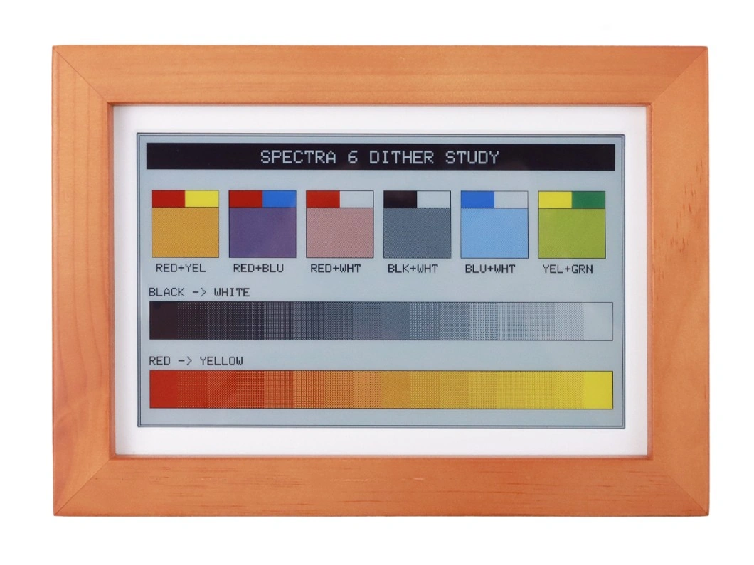
#include <SPI.h>
#include <Wire.h>

#define XPOWERS_CHIP_AXP2101
#include <XPowersLib.h>
#include <GxEPD2_7C.h>

constexpr int PMU_SDA = 47;
constexpr int PMU_SCL = 48;

constexpr int EPD_DC = 8;
constexpr int EPD_CS = 9;
constexpr int EPD_SCLK = 10;
constexpr int EPD_MOSI = 11;
constexpr int EPD_RST = 12;
constexpr int EPD_BUSY = 13;

using EpdDriver = GxEPD2_730c_GDEP073E01;

// Buffer 40 lines at a time: 800 × 40 × 4 ÷ 8 = 16000 bytes
GxEPD2_7C<EpdDriver, 40> display(
  EpdDriver(EPD_CS, EPD_DC, EPD_RST, EPD_BUSY));

XPowersPMU power;

bool initEpaperPower() {
  if (!power.begin(
        Wire, AXP2101_SLAVE_ADDRESS, PMU_SDA, PMU_SCL)) {
    Serial.println("AXP2101 initialization failed.");
    return false;
  }

  // Set and enable the 3.3 V supply for the E-Paper display
  if (!power.setALDO4Voltage(3300)) {
    Serial.println("Failed to set ALDO4 to 3.3 V.");
    return false;
  }

  if (!power.enableALDO4()) {
    Serial.println("Failed to enable ALDO4.");
    return false;
  }

  delay(10);
  return true;
}

// Standard 4×4 Bayer threshold matrix; its 16 positions contain every value from 0 to 15
const uint8_t kBayer4x4[4][4] = {
  { 0,  8,  2, 10},
  {12,  4, 14,  6},
  { 3, 11,  1,  9},
  {15,  7, 13,  5},
};

// Dither-fill a rectangle, mixing colorB into colorA at a ratio of level/16
void fillRectDithered(int16_t x, int16_t y, int16_t w, int16_t h,
                      uint16_t colorA, uint16_t colorB, uint8_t level) {
  for (int16_t dy = 0; dy < h; ++dy) {
    for (int16_t dx = 0; dx < w; ++dx) {
      const uint16_t color =
        level > kBayer4x4[dy & 3][dx & 3] ? colorB : colorA;
      display.drawPixel(x + dx, y + dy, color);
    }
  }
}

// Six mixed-color patches: two native solid colors above, with their 1:1 dithered mix below
void drawMixedSwatches() {
  const uint16_t mixes[6][2] = {
    {GxEPD_RED, GxEPD_YELLOW},   // Orange
    {GxEPD_RED, GxEPD_BLUE},     // Purple
    {GxEPD_RED, GxEPD_WHITE},    // Pink
    {GxEPD_BLACK, GxEPD_WHITE},  // Gray
    {GxEPD_BLUE, GxEPD_WHITE},   // Light blue
    {GxEPD_YELLOW, GxEPD_GREEN}, // Yellow-green
  };
  const char *labels[6] = {
    "RED+YEL", "RED+BLU", "RED+WHT",
    "BLK+WHT", "BLU+WHT", "YEL+GRN"
  };

  display.setTextSize(2);
  display.setTextColor(GxEPD_BLACK);
  for (int i = 0; i < 6; ++i) {
    const int16_t x = 20 + i * 128;
    display.fillRect(x, 90, 56, 28, mixes[i][0]);
    display.fillRect(x + 56, 90, 56, 28, mixes[i][1]);
    fillRectDithered(x, 118, 112, 84, mixes[i][0], mixes[i][1], 8);
    display.drawRect(x, 90, 112, 112, GxEPD_BLACK);
    display.drawFastHLine(x, 118, 112, GxEPD_BLACK);
    display.setCursor(x + 8, 212);
    display.print(labels[i]);
  }
}

// 16-step dithered gradient; the first step is pure colorA and the last is pure colorB
void drawGradientBar(int16_t x, int16_t y, int16_t w, int16_t h,
                     uint16_t colorA, uint16_t colorB) {
  const int16_t stepW = w / 16;
  for (int i = 0; i < 16; ++i) {
    // Map steps 0–15 to dithering levels 0–16
    fillRectDithered(x + i * stepW, y, stepW, h,
                     colorA, colorB, i * 16 / 15);
  }
  display.drawRect(x, y, w, h, GxEPD_BLACK);
}

void drawDitherStudy() {
  display.fillScreen(GxEPD_WHITE);
  display.setTextWrap(false);

  // Black title bar
  display.fillRect(12, 12, 776, 44, GxEPD_BLACK);
  display.setTextColor(GxEPD_WHITE);
  display.setTextSize(3);
  display.setCursor(202, 24);
  display.print("SPECTRA 6 DITHER STUDY");

  drawMixedSwatches();

  display.setTextSize(2);
  display.setTextColor(GxEPD_BLACK);
  display.setCursor(16, 252);
  display.print("BLACK -> WHITE");
  drawGradientBar(16, 274, 768, 64, GxEPD_BLACK, GxEPD_WHITE);

  display.setCursor(16, 366);
  display.print("RED -> YELLOW");
  drawGradientBar(16, 388, 768, 64, GxEPD_RED, GxEPD_YELLOW);

  display.drawRect(0, 0, 800, 480, GxEPD_BLACK);
}

void setup() {
  Serial.begin(115200);
  delay(100);

  if (!initEpaperPower()) {
    Serial.println("EPD power initialization failed.");
    while (true) {
      delay(1000);
    }
  }

  // Initialize the E-Paper display using the onboard SPI pins
  SPI.begin(EPD_SCLK, -1, EPD_MOSI, EPD_CS);
  display.epd2.selectSPI(
    SPI, SPISettings(4000000, MSBFIRST, SPI_MODE0));

  display.init(115200);
  // Rotate the image to match the board's viewing orientation
  display.setRotation(2);
  display.setFullWindow();

  // Draw in pages and refresh the full screen
  display.firstPage();
  do {
    drawDitherStudy();
  } while (display.nextPage());

  // Put the display into sleep after the refresh completes
  display.hibernate();
  Serial.println("Dither study refresh completed.");
}

void loop() {
}
Six-Color Pixel Encoding and Display Memory
The GxEPD2_7C page buffer stores pixels at 4 bpp, so one byte records two pixels: the first pixel occupies the high four bits, and the second occupies the low four bits. GxEPD2 first converts color constants to page-buffer encoding, after which the GxEPD2_730c_GDEP073E01 driver converts them to the panel's native encoding.
| Color | GxEPD2 Color Constant | Page-Buffer Encoding | Panel-Native Encoding |
|---|---|---|---|
| Black | GxEPD_BLACK | 0000 (0x0) | 0000 (0x0) |
| White | GxEPD_WHITE | 0001 (0x1) | 0001 (0x1) |
| Green | GxEPD_GREEN | 0010 (0x2) | 0110 (0x6) |
| Blue | GxEPD_BLUE | 0011 (0x3) | 0101 (0x5) |
| Red | GxEPD_RED | 0100 (0x4) | 0011 (0x3) |
| Yellow | GxEPD_YELLOW | 0101 (0x5) | 0010 (0x2) |
The mapping above is based on the GxEPD2_7C.h and GxEPD2_730c_GDEP073E01.cpp files for the GxEPD2 version listed in General Preparation. The table lists only the six colors used here. For example, if two consecutive pixels are green and red, the page-buffer data is 0010 0100, or 0x24. Before sending it to the panel, the driver converts it to 0110 0011, or 0x63. You do not need to handle this conversion manually when using the Adafruit GFX drawing interface. You need to arrange pixels according to the panel-native encoding only when writing native image data directly.
A complete 800×480 frame buffer requires 800 × 480 × 4 ÷ 8 = 192000 bytes, approximately 187.5 KB. Both examples above set the template parameter to 40 and use paged rendering, buffering only 40 lines at a time for a total of 16000 bytes. firstPage() and nextPage() draw each page in sequence and complete the full-screen refresh.
Using the Waveshare Official Library
The Waveshare official photo-frame project provides a complete implementation for the ESP32-S3-PhotoPainter, covering AXP2101 power configuration, SD card FATFS file access, image conversion through dithering, and the display refresh sequence. The basic call sequence is:
DEV_Module_Init();      // Initialize the hardware and the AXP2101 PMIC
EPD_7IN3E_Init();       // Initialize the 7.3-inch Spectra 6 E-Paper display
EPD_7IN3E_Show();       // Read and display an image; six-color conversion and dithering are handled internally
EPD_7IN3E_Sleep();      // Put the display driver into sleep after the refresh completes
The official project already integrates the Floyd–Steinberg error-diffusion algorithm and SD card image cycling, which suits building a photo frame directly or checking the low-level driver. For the complete program, see the ESP32-S3-PhotoPainter official repository. For development environment and firmware flashing instructions, see the ESP32-S3-PhotoPainter Wiki.
Refresh and Sleep
A standard full refresh on a full-color E-Paper display takes a long time, approximately 30 seconds. During a refresh, wait for EPD_BUSY to be released; do not reset the device or disconnect power. After nextPage() completes the full-screen refresh, call display.hibernate() to place the display driver in deep sleep.
If you use another E-Paper display, consult its product documentation to determine whether it supports partial refresh, the permitted partial-refresh area, and the minimum interval between refreshes.
- A full-color E-Paper refresh takes a long time and drives the waveform through several inversion stages. Leave an adequate interval between refreshes, such as no less than 180 seconds, so that frequent refreshes do not accelerate panel aging.
- Always put the display driver into deep sleep after the image is shown: call
display.hibernate()with GxEPD2 orEPD_7IN3E_Sleep()with the Waveshare official library. display.hibernate()manages only the display driver IC. Whole-device low-power operation also requires ESP32-S3 deep sleep and, where applicable, switching off peripheral supplies through the AXP2101.- Refresh the display to white before disconnecting power for long-term storage.
5.5 Troubleshooting
| Symptom | Common Cause | Solution |
|---|---|---|
| The display still shows the previous image after uploading | E-Paper retains its image without power, so the screen does not change at all if the program fails to run | Re-upload using the Arduino project settings from the corresponding product page (board model, USB CDC On Boot, Flash Size, Partition Scheme, and PSRAM), then reset the board or reconnect USB. No serial output is an indication that the program is not running |
| The display does not respond | Display power is not enabled; SPI pins have not been remapped | Enable display power as described in the board documentation (it may be controlled by a GPIO or power-management IC). Confirm that SPI.begin() is called with the correct pins before display.init() |
| The program stalls during initialization or the refresh never finishes | The BUSY pin is incorrect, so the driver waits indefinitely for the busy state to be released | Verify the BUSY pin number. GxEPD2 prints Busy Timeout to the serial port when the wait times out, which can be used as a diagnostic |
| The driver class is not found during compilation | The GxEPD2 version is too old to support the panel | Upgrade GxEPD2. The black-and-white ESP32-S3-ePaper-3.97 panel requires v1.6.5 or later, the four-color ESP32-S3-ePaper-1.54G panel requires v1.6.6 or later, and the six-color ESP32-S3-PhotoPainter panel requires v1.5.9 or later |
| The image refreshes, but the content is incorrect (gray, wrong colors, or mirrored) | The panel driver class does not match the actual panel | Select the driver class by panel model, not by driver IC model |
| Photographs on the full-color display look grainy up close and less vivid than the sample image | The six-color panel uses dithering to simulate non-native colors; this is part of its normal display principle | See Displaying Mixed Colors with Dithering. Increase the viewing distance to make the color mixing look more natural |
| Ghosting appears after several partial refreshes | Error from partial refresh accumulates; this is normal | Perform one full refresh to clear it. Follow the refresh-mechanism strategy and perform a full refresh periodically; see Full Refresh vs. Partial Refresh for code |
| A trace of the previous image remains after a full refresh | The panel driver uses fast full refresh by default, so the particles are not reset completely | On panels that provide fast full refresh, call display.epd2.selectFastFullUpdate(false) to switch to standard full refresh |
| The display cannot refresh after sleep | After hibernate(), the driver is in deep sleep and no longer responds to data | Turn display power back on (if it was previously turned off) and reinitialize the display driver |
| Refreshes slow down and ghosting increases at low temperatures | Electrophoretic particles move more slowly at low temperatures | Confirm that the ambient temperature is within the display's specified operating range |