LCD
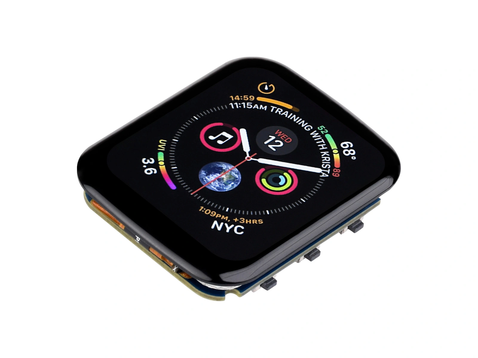
LCDs (liquid-crystal displays) are widely used in ESP32 projects. They support full color, are available in many sizes and resolutions, cost relatively little, and have mature driver support. An LCD is a practical starting point when an application does not require a more specialized display technology.
This page covers the operating principles and controllers used by the color active-matrix TFT LCDs commonly found in ESP32 projects. Segment LCDs and monochrome dot-matrix LCDs are outside its scope. Read Display Fundamentals and Interfaces first if you are unfamiliar with the shared concepts.
1. Operating Principle
Most LCDs are transmissive. The liquid crystals do not emit light; a backlight beneath the panel provides the light, and the liquid-crystal layer controls how much passes through.
A reflective LCD (RLCD) uses ambient light and requires no backlight. It is covered separately in RLCD.
The following sections begin with the structure of a pixel and then explain how an LCD controls color.
1.1 Pixel Structure and Arrangement
Under magnification, each LCD pixel consists of three narrow red, green, and blue subpixels placed side by side. A vertical RGB stripe is the most common arrangement, but the physical order is not necessarily R, G, B.

A 240×320 panel therefore contains 720 (240×3) subpixel columns and 320 rows. A subpixel is the smallest controllable unit on the panel. Each has its own electrode. The color filter above it is fixed, so the subpixel cannot change color; only its brightness can be varied.
The color of one pixel is set by controlling the brightness of its three subpixels. All three at maximum brightness produce white; all three off produce black; red alone produces red; and red plus green produces yellow. At a normal viewing distance, the eye combines the three subpixels into a single perceived color.
1.2 How a Subpixel Controls Light
Several panel layers work together to control brightness. The liquid-crystal layer acts as a voltage-controlled light valve. Voltage changes the orientation of the molecules, which changes the polarization of the transmitted light. Polarizers turn that change into a change in brightness.
Liquid-crystal alignment differs among panel technologies. The following simplified twisted-nematic (TN) example shows the layers directly involved in light control, from the backlight to the viewing surface:

- Backlight: LEDs and a light guide provide uniform white light.
- Vertical polarizer: Converts the unpolarized light from the backlight into vertically polarized light.
- Liquid-crystal layer: The molecules form a twisted arrangement that rotates the polarization of passing light. Applying voltage aligns the molecules with the electric field. Higher voltage reduces the twist and therefore reduces the rotation.
- Horizontal polarizer: Its transmission axis is perpendicular to the first polarizer. A complete 90° liquid-crystal twist rotates the light so it passes through and produces maximum brightness. With no twist, the light remains vertical and is blocked. Intermediate angles transmit part of the light, allowing continuously variable brightness.
- Color filter: A fixed filter above each subpixel passes only its assigned color.
The two polarizers are perpendicular. Without the liquid-crystal layer, the second polarizer would block the light and the panel would remain black. In combination, the backlight supplies light, the polarizers define its orientation, the liquid crystals control transmission, and the color filters select red, green, or blue.
1.3 From Pixel Data to Color
In RGB565, a 16-bit pixel assigns 5 bits to red, 6 to green, and 5 to blue. This provides 32 brightness levels for red and blue and 64 for green. See Color Depth for the reason behind this allocation. The controller converts each component into the voltage applied to the corresponding subpixel:
| RGB565 pixel value | R / G / B components | Subpixel state | Displayed color |
|---|---|---|---|
0xFFFF | 31 / 63 / 31 | All transmit maximum light | White |
0x0000 | 0 / 0 / 0 | All block light | Black |
0xF800 | 31 / 0 / 0 | Red transmits | Red |
0xFFE0 | 31 / 63 / 0 | Red and green transmit | Yellow |
The microcontroller writes pixel values to the controller's graphics RAM (GRAM; see Display Fundamentals and Interfaces). The controller then generates the subpixel voltages and scans the panel.
This principle explains two inherent LCD characteristics:
- Black is not perfectly black: The backlight remains on, and the liquid crystals cannot block every trace of light. Black therefore appears gray and contrast is lower than on a self-emissive OLED or AMOLED.
- Power varies little with image content: At a fixed brightness, the continuously operating backlight accounts for most module power. Changing the image has much less effect than it does on an OLED or AMOLED.
1.4 TN and IPS
Two liquid-crystal arrangements are common in embedded panels. In a TN (Twisted Nematic) panel, the molecules twist between the upper and lower substrates and untwist as voltage is applied, as illustrated in How a Subpixel Controls Light. An IPS (In-Plane Switching) panel places both electrodes on the same substrate, and its molecules rotate mainly in a plane parallel to the panel. The optical state of an IPS panel therefore changes less with viewing direction, providing wider viewing angles and better color reproduction.
| Panel type | Viewing angle | Color reproduction | Cost |
|---|---|---|---|
| TN | Narrow; colors shift and wash out off-axis | Fair | Low |
| IPS | Nearly full viewing angle | Good | Slightly higher |
2. Advantages and Limitations
Advantages:
- Full-color output suitable for GUIs such as LVGL.
- Mature products from below 1 inch to more than 7 inches.
- Generally the lowest-cost full-color panel technology, with extensive driver and library support.
- No OLED-style burn-in, making LCD suitable for static content shown for long periods.
Limitations:
- The backlight consumes power continuously. It can be dimmed with PWM through the module's BL pin, but LCD is not ideal for an always-on battery-powered device.
- Limited contrast and gray-looking black.
- Only moderate readability in direct sunlight because ambient light overwhelms the backlight.
For lower power or better outdoor readability, compare RLCD and e-paper in the display overview.
3. Common Controllers and Interfaces
An LCD module typically consists of a panel, backlight, display controller, and FPC. The microcontroller communicates with the display controller rather than directly with the panel. The controller model matters more than the physical display size because it determines the initialization commands, supported interfaces, and maximum resolution.
| Controller | Common panel resolutions | Common interfaces | Typical displays |
|---|---|---|---|
| ST7735S | 80×160 / 128×160 | SPI | 0.96–1.8-inch compact displays |
| GC9A01 | 240×240 | SPI | 1.28-inch round displays |
| ST7789 | 240×240 / 240×280 / 240×320 | SPI / I80 | Common 1.3–2.4-inch displays |
| ST7796 | 320×480 | SPI / I80 | 3.5–4-inch displays |
| AXS15231B | 320×480 / 172×640 | QSPI | 3.49–3.5-inch displays |
| ST77916 | 360×360 | QSPI | 1.85-inch round or square displays |
Important details:
-
SPI, I80, and QSPI controllers usually receive pixels and scan the panel internally. An RGB panel is scanned continuously by ESP32-S3, ESP32-S31, or ESP32-P4 and uses a different driver architecture.
-
A controller may support multiple interfaces, but the panel FPC determines which one is exposed by a module. Check the product page.
-
The panel resolution can be smaller than the controller's GRAM. A 240×280 panel using ST7789, whose GRAM is 240×320, maps to GRAM rows 20–299. The driver sets the display window from the start row and display height: the start row is 20, and the final row is
20 + 280 - 1 = 299. The remaining 20 rows do not need a separate setting. Incorrect offsets shift the image or corrupt its edges.
4. Arduino_GFX Example
The same structure applies to any ESP32 board. This example uses the Waveshare ESP32-S3-Touch-LCD-1.69, which includes a 1.69-inch 240×280 IPS panel driven by ST7789V2. For another board or module, change the pin definitions and display-controller class, then adjust the resolution and offset parameters for the actual panel.
The example uses the open-source GFX Library for Arduino. It supports SPI, QSPI, I80, RGB, and many common display controllers.
4.1 Install the Library
In the Arduino IDE Library Manager, search for and install GFX Library for Arduino. See Installing Arduino Libraries for other installation methods.
4.2 Confirm the Pins
The ESP32-S3-Touch-LCD-1.69 display is connected directly to the microcontroller:
| Signal | GPIO | Description |
|---|---|---|
| LCD_DC | GPIO4 | Command/data selection |
| LCD_CS | GPIO5 | Chip select |
| LCD_CLK | GPIO6 | SPI clock |
| LCD_DIN | GPIO7 | SPI MOSI |
| LCD_RST | GPIO8 | Reset |
| LCD_BL | GPIO15 | Backlight control |
4.3 Example Code
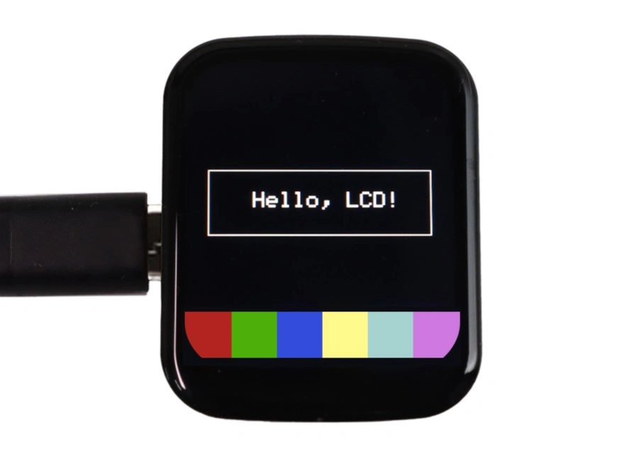
After building and uploading the following example, the display shows “Hello, LCD!”, a white outline, and red, green, blue, yellow, cyan, and magenta blocks on a black background.
#include <Arduino_GFX_Library.h>

// Pin definitions for ESP32-S3-Touch-LCD-1.69 or ESP32-S3-LCD-1.69
#define LCD_DC 4
#define LCD_CS 5
#define LCD_CLK 6
#define LCD_DIN 7
#define LCD_RST 8
#define LCD_BL 15

// 1. Create the SPI bus object.
Arduino_DataBus *bus = new Arduino_ESP32SPI(
    LCD_DC, LCD_CS, LCD_CLK, LCD_DIN, GFX_NOT_DEFINED /* MISO not required */);

// 2. Create an ST7789 display object for a 240×280 inverted panel
//    with a 20-row GRAM offset.
Arduino_GFX *gfx = new Arduino_ST7789(
    bus, LCD_RST, 0 /* initial rotation */, true /* enable inversion */,
    240 /* width */, 280 /* height */,
    0 /* column offset 1 */, 20 /* row offset 1 */,
    0 /* column offset 2 */, 20 /* row offset 2 */);

void setup() {
  // 3. Initialize the display.
  gfx->begin();

  // 4. Turn on the backlight (HIGH is maximum brightness; connect this pin to LEDC PWM for brightness control).
  pinMode(LCD_BL, OUTPUT);
  digitalWrite(LCD_BL, HIGH);

  // 5. Clear the display.
  gfx->fillScreen(RGB565_BLACK);

  // 6. Draw text.
  gfx->setTextColor(RGB565_WHITE);
  gfx->setTextSize(2);
  gfx->setCursor(60, 120);
  gfx->println("Hello, LCD!");

  // 7. Draw a white rectangular outline.
  gfx->drawRect(20, 100, 200, 60, RGB565_WHITE);

  // 8. Draw color blocks along the bottom.
  int blockY = 230;
  int blockW = 40;
  int blockH = 40;

  gfx->fillRect(0,   blockY, blockW, blockH, RGB565_RED);
  gfx->fillRect(40,  blockY, blockW, blockH, RGB565_GREEN);
  gfx->fillRect(80,  blockY, blockW, blockH, RGB565_BLUE);
  gfx->fillRect(120, blockY, blockW, blockH, RGB565_YELLOW);
  gfx->fillRect(160, blockY, blockW, blockH, RGB565_CYAN);
  gfx->fillRect(200, blockY, blockW, blockH, RGB565_MAGENTA);
}

void loop() {
}
Arduino_DataBus handles bus transfers, while Arduino_ST7789 handles display-controller commands. This corresponds to the layers described in Display Fundamentals and Interfaces. gfx->begin() performs reset and initialization. The drawing API then sets write windows and transfers pixels.
Only the pin definitions and constructors are hardware-specific. After initialization, the drawing code is independent of the display. You can reuse this configuration in the library's drawing examples or call the drawing API from your own application. To find other examples, search for the library name in the IDE's Examples menu.
The fourth Arduino_ST7789 argument is named ips and controls the display-inversion state during initialization: true sends INVON, while false sends INVOFF. Many ST7789 IPS panels require inversion for correct colors. If black and white or red and cyan appear swapped, try the other value.
row_offset1 and row_offset2 provide display-window start-address compensation for two rotation groups. Rotations 0/1 use row_offset1, while rotations 2/3 use row_offset2; after rotation, the offset applies to the corresponding coordinate axis. Both row offsets are 20 in this example. The panel and GRAM are both 240 pixels wide, so both column offsets are 0.
The offset in this example happens to be half the height difference, but that result applies only to this panel. Determine offsets from the active region's position and the rotation direction. For example, configurations in the official library use a row offset of 80 for some 240×240 panels and column offsets of 52 and 53 for a 135×240 panel. Use the product example, panel documentation, or graphics-library configuration for the actual module.
See the Arduino_GFX Data Bus Class and Display Class pages for supported buses, controllers, and constructor arguments.
4.4 Rotate the Display
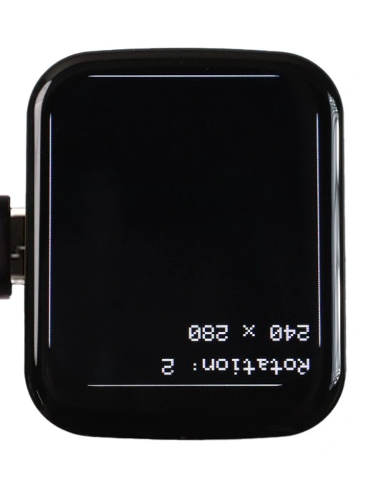
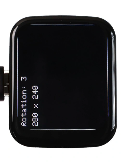
ST7789V2 uses the MADCTL register to change row and column scan direction. Arduino_GFX accepts rotation values from 0 through 3 in the constructor and setRotation(), representing orientations 90° apart. The library updates the coordinate system and GRAM offsets; logical width and height are exchanged in landscape orientations.
| Rotation | Relative to rotation 0 | Logical resolution |
|---|---|---|
0 | 0° | 240×280 |
1 | 90° | 280×240 |
2 | 180° | 240×280 |
3 | 270° | 280×240 |
The third constructor argument sets the initial rotation. Change 0 to 1 or 3 for a fixed landscape layout. Use setRotation() when the orientation must change after initialization.
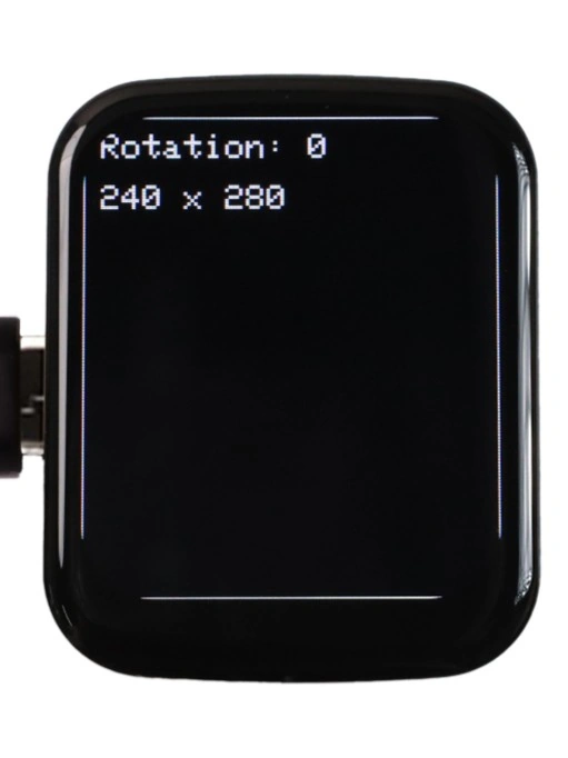
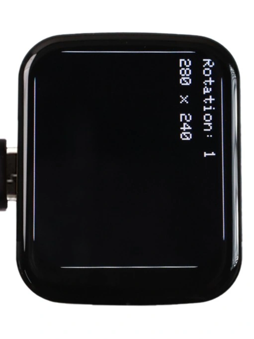
The following program changes orientation every two seconds and redraws its border and text in the new coordinate system. The four orientations appear as follows:
| Rotation 0 | Rotation 1 | Rotation 2 | Rotation 3 |
|---|---|---|---|
 |  |  |  |
#include <Arduino_GFX_Library.h>

// Pin definitions for ESP32-S3-Touch-LCD-1.69 or ESP32-S3-LCD-1.69
#define LCD_DC 4
#define LCD_CS 5
#define LCD_CLK 6
#define LCD_DIN 7
#define LCD_RST 8
#define LCD_BL 15

// Create the SPI bus object.
Arduino_DataBus *bus = new Arduino_ESP32SPI(
    LCD_DC, LCD_CS, LCD_CLK, LCD_DIN, GFX_NOT_DEFINED /* MISO not required */);

// Create an ST7789 display object for a 240×280 inverted panel
// with a 20-row GRAM offset.
Arduino_GFX *gfx = new Arduino_ST7789(
    bus, LCD_RST, 0 /* initial rotation */, true /* enable inversion */,
    240 /* width */, 280 /* height */,
    0 /* column offset 1 */, 20 /* row offset 1 */,
    0 /* column offset 2 */, 20 /* row offset 2 */);

void drawRotationDemo(uint8_t rotation) {
  gfx->setRotation(rotation);
  gfx->fillScreen(RGB565_BLACK);

  gfx->drawRect(0, 0, gfx->width(), gfx->height(), RGB565_WHITE);
  gfx->setTextColor(RGB565_WHITE);
  gfx->setTextSize(2);
  gfx->setCursor(10, 10);
  gfx->print("Rotation: ");
  gfx->println(rotation);

  gfx->setCursor(10, 40);
  gfx->print(gfx->width());
  gfx->print(" x ");
  gfx->println(gfx->height());
}

void setup() {
  gfx->begin();

  pinMode(LCD_BL, OUTPUT);
  digitalWrite(LCD_BL, HIGH);
}

void loop() {
  static uint8_t rotation = 0;

  drawRotationDemo(rotation);
  rotation = (rotation + 1) % 4;
  delay(2000);
}
setRotation() writes MADCTL to change the controller's addressing direction and updates the library's logical coordinate system. It does not rotate pixels already stored in GRAM, so clear and redraw the display after changing orientation.
4.5 Troubleshooting
| Symptom | Likely cause | Corrective action |
|---|---|---|
| White screen / no image | Incorrect wiring or pin definitions; backlight disabled | Check the pin table and confirm that BL is high |
| Shifted image or corrupted edge | Incorrect GRAM offsets | Use the constructor offsets from the product example or panel documentation |
| All colors inverted | Inversion setting does not match the panel | Change the ips argument or call invertDisplay() |
| Red and blue swapped | RGB/BGR subpixel order mismatch | Set the color-order option provided by the driver class |
| Correct image but slow updates | Update region is too large or SPI bandwidth is insufficient | Reduce the update area first. You may test gfx->begin(80000000) for an 80 MHz SPI clock, but this exceeds the ST7789V2 specified write timing; return to the default 40 MHz if operation is unstable. |