LED Matrix
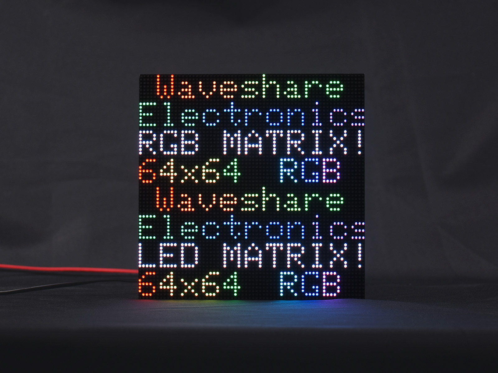
An LED matrix consists of many individually packaged RGB LEDs arranged in rows and columns, with each LED package forming one pixel. Unlike LCD and OLED displays, which integrate the pixel structure into the panel, common HUB75 matrix modules use relatively large, individually packaged LEDs with clearly visible spacing between pixels, known as pixel pitch. Their high brightness and modular construction make them suitable for signs, information displays, scoreboards, and other applications viewed from a distance.
Full-color LED matrices with a HUB75 interface are commonly used in embedded systems. This chapter explains the imaging principle of an LED matrix and the HUB75 row-scanning mechanism. It then demonstrates how to drive a Waveshare RGB-Matrix-P2.5-64x64 with an ESP32-S3-RGB-Matrix driver board.
Before reading this chapter, review the color-depth and framebuffer concepts in Display Fundamentals and Interfaces.
1. Display Principle
A full-color LED matrix is an M×N array of LEDs. Each pixel is a single package containing red, green, and blue light-emitting dies (1R1G1B), which mix their light to produce full color.
The large number of pixels makes it impractical to wire each pixel separately—a 64×64 display has 4096 pixels and 12288 light-emitting dies. An LED matrix therefore uses row/column scanning and shift registers, which is also the operating principle of the HUB75 interface:
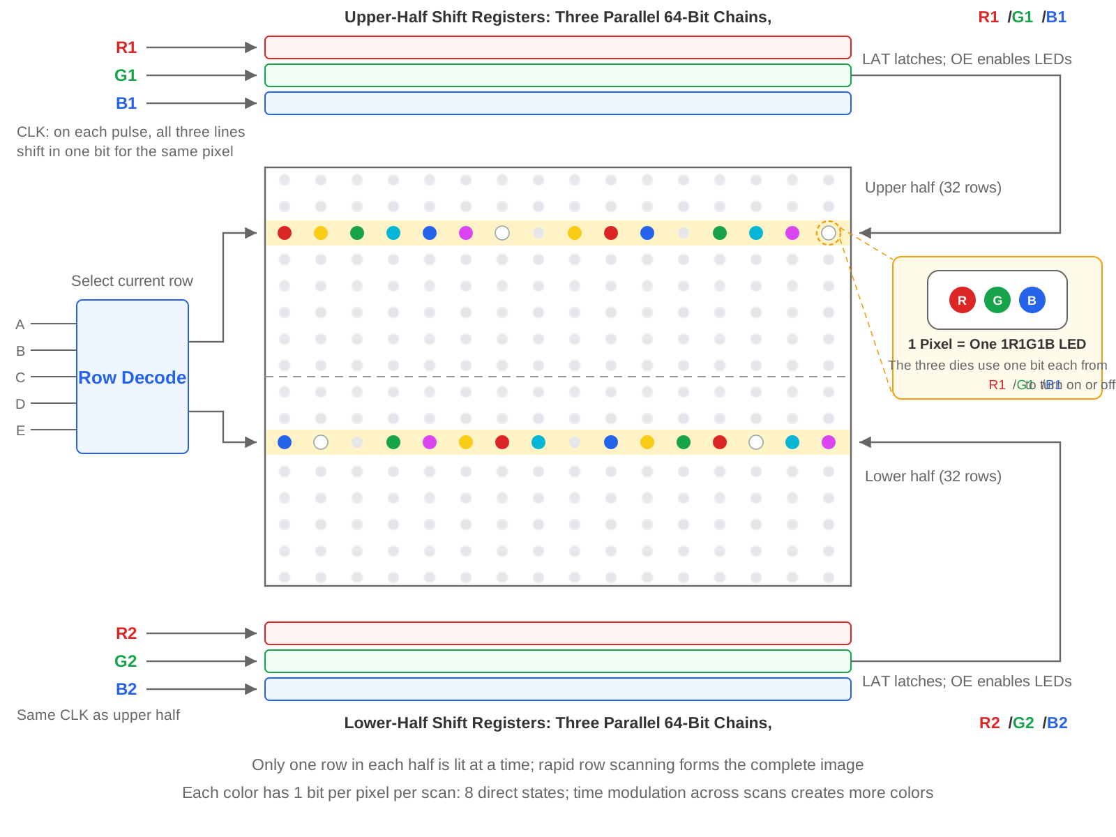
- Column data is shifted in serially: The display is divided into upper and lower halves vertically.
R1/G1/B1are three parallel data lines corresponding to three independent red, green, and blue shift chains for the upper half. On everyCLKpulse, each chain shifts in one bit, providing the three color bits for the same pixel. Filling one complete row requires one clock pulse per column.R2/G2/B2load data for the current row in the lower half in the same way. - Address lines select the current scan row: The
A/B/C/D/Erow-address lines are decoded to select the current pair of scan rows, one in each half of the display. - Latch and enable: After a complete row has been shifted in,
LATlatches the shift-register contents to the outputs.OE(Output Enable, active low) controls whether the row is illuminated.
At any instant, only one row in each half of the display is illuminated. Rapid row-by-row scanning combined with persistence of vision creates the complete image. The host controller must keep this "scanning" process running continuously; if it stops, the image cannot be maintained. This differs from an SPI display: an SPI display's driver IC includes display memory, so it can maintain an image after the host writes a frame. An LED matrix instead requires the host to refresh it repeatedly at high speed. The ESP32 uses I2S or an LCD parallel peripheral together with DMA (Direct Memory Access) to perform this continuous refresh automatically in the background without CPU intervention for every row. This is the key to driving an LED matrix smoothly.
Another important point is how grayscale is produced. Each color data line carries only one bit, so each die can only be on or off during a single scan, yielding only 2³ = 8 colors directly. A richer color range is created with BCM (Binary Code Modulation) dimming. The driver splits a color value into multiple bitplanes, scans each bitplane repeatedly, and assigns illumination time according to each bit's weight. The eye blends these intervals into continuous grayscale.
The display's scan ratio determines how many address lines it uses. The RGB-Matrix-P2.5-64x64 uses 1/32 scan: its 64 rows are divided into upper and lower halves of 32 rows each, requiring five address lines (A/B/C/D/E, 2⁵ = 32). A lower-resolution 64×32 display uses 1/16 scan and only four address lines (A/B/C/D, 2⁴ = 16), leaving E disconnected.
In interface naming, a connector using only A through D is called HUB75, while one that adds E is often called HUB75E. Both use a 16-pin ribbon cable. Vendor naming is inconsistent, so this chapter uses HUB75 as the general term.
Pixel pitch is the distance between the centers of adjacent pixels and is a key LED-matrix specification. P2.5 means a pitch of 2.5 mm. A smaller number indicates denser pixels: at the same 64×64 resolution, a P2.5 display measures 160×160 mm, while a P3 display measures 192×192 mm. An LED matrix's native resolution is determined by its physical LED count. The package size, PCB routing, and thermal spacing of the individually packaged LEDs all have lower limits, so pixel density is significantly lower than that of an LCD or OLED panel of the same size.
2. Features and Limitations
Advantages:
- Can achieve very high brightness, making it suitable for long viewing distances and bright environments.
- Modular design. HUB75 cascade connectors allow modules to be tiled in integer multiples to form a larger display, while individual modules remain easy to install, replace, and maintain.
- Full-color, emissive display with a wide viewing angle (≥140°).
- Some models use GOB (Glue On Board) encapsulation to improve impact, moisture, and dust resistance.
Limitations:
- Large pixel pitch produces obvious grain and uncomfortably high brightness at close range. A suitable viewing distance is required for a good visual result.
- Each pixel is an individually packaged LED, resulting in low resolution and pixel density. The display is unsuitable for fine text and graphics.
- The image depends on continuous high-speed refresh, and DMA buffers consume a substantial amount of internal RAM. Usage increases with resolution and color depth; even one 64×64 module requires tens of kilobytes.
- High power and current consumption. At full white and maximum brightness, current can reach several amperes. The RGB-Matrix-P2.5-64x64 is rated at 5 V / 4 A and ≤20 W and requires a separate 5 V power supply.
- Requires a dedicated HUB75 driving solution, making wiring and power delivery more complex than for a small display module.
3. Interface and Driver Options
The HUB75 interface is the de facto standard for full-color LED matrices. It uses a 16-pin (2×8) ribbon cable with the following main signals:
| Signal | Meaning |
|---|---|
| R1 / G1 / B1 | Red/green/blue data for the upper half |
| R2 / G2 / B2 | Red/green/blue data for the lower half |
| A / B / C / D / E | Row-address lines (E is used only by 1/32-scan displays, which use the HUB75E interface) |
| CLK | Shift clock |
| LAT (STB) | Latch |
| OE | Output enable (active low) |
| GND | Ground |
The HUB75 ribbon cable carries control signals and a ground reference; it does not supply the LEDs with 5 V operating power. Power the matrix through the dedicated 5 V connector on the display or driver board, such as the VH4 connector on the RGB-Matrix-P2.5-64x64, using a supply that meets the display's rated current. Never draw the LEDs' operating current from a host GPIO, a 3.3 V pin, or the ordinary 5 V pin on a development board.
Driver options: As described under Display Principle, the host must refresh the matrix continuously at high speed. The ESP32 series performs this work automatically in the background using a high-speed parallel peripheral with DMA:
- The original ESP32 uses the I2S peripheral's LCD parallel mode.
- The ESP32-S3 uses its LCD parallel peripheral with GDMA (General DMA Controller; see the ESP32-S3 Technical Reference Manual) for better performance.
The Waveshare ESP32-S3-RGB-Matrix driver board integrates the ESP32-S3, a HUB75 ribbon-cable connector, and the display power connector. You can connect the matrix directly, without designing the signal wiring or power circuitry yourself. The examples in this chapter use this driver board.
4. Arduino + ESP32-HUB75-MatrixPanel-DMA Driver Example
ESP32-HUB75-MatrixPanel-DMA is a community-maintained HUB75 matrix driver library. It uses an ESP32 parallel peripheral with DMA to refresh the display automatically in the background and is a popular Arduino option for driving these panels. The I2S names in the library's header and class names are retained from the earlier implementation for the original ESP32 I2S peripheral; they are historical names, and the ESP32-S3 implementation actually uses the LCD parallel peripheral. The drawing API inherits from Adafruit GFX, so functions such as drawRect(), drawCircle(), and print() work the same way as in other common graphics libraries.
This section uses a Waveshare ESP32-S3-RGB-Matrix driver board with an RGB-Matrix-P2.5-64x64 display. The panel has a 64×64 resolution, uses 1/32 scan, has conventional shift-register driver ICs, and scans the upper and lower halves in parallel. For another conventional 1/16- or 1/32-scan display, confirm the resolution, cascade count, and pin configuration. Panels with unusual row decoding, pixel mapping, or driver ICs with internal PWM also require a different driver type or VirtualMatrixPanel.
4.1 Install the Library
In Library Manager, search for and install ESP32 HUB75 LED MATRIX PANEL DMA Display. If prompted to install dependency libraries, install those as well. See Installing Arduino Libraries for other installation methods.
4.2 Confirm the Pins
The ESP32-S3-RGB-Matrix driver board connects its HUB75 signals to fixed ESP32-S3 GPIOs:
| HUB75 Signal | GPIO | HUB75 Signal | GPIO |
|---|---|---|---|
| R1 | 4 | R2 | 7 |
| G1 | 5 | G2 | 15 |
| B1 | 6 | B2 | 16 |
| A | 18 | B | 8 |
| C | 3 | D | 42 |
| E | 9 | CLK | 41 |
| LAT | 40 | OE | 2 |
No manual signal wiring is required with this driver board. Connect the matrix's HUB75 ribbon cable to the corresponding connector on the driver board and connect the display to a 5 V supply. The PCB traces and HUB75 interface already provide a common ground between the display and host, so no separate ground wire is needed. The library's default ESP32-S3 pins happen to match this driver board except for E, but the example still declares every pin explicitly to demonstrate manual pin assignment and the required signal order. When wiring another development board manually, change pins in the example to match the actual connections.
4.3 Example Code
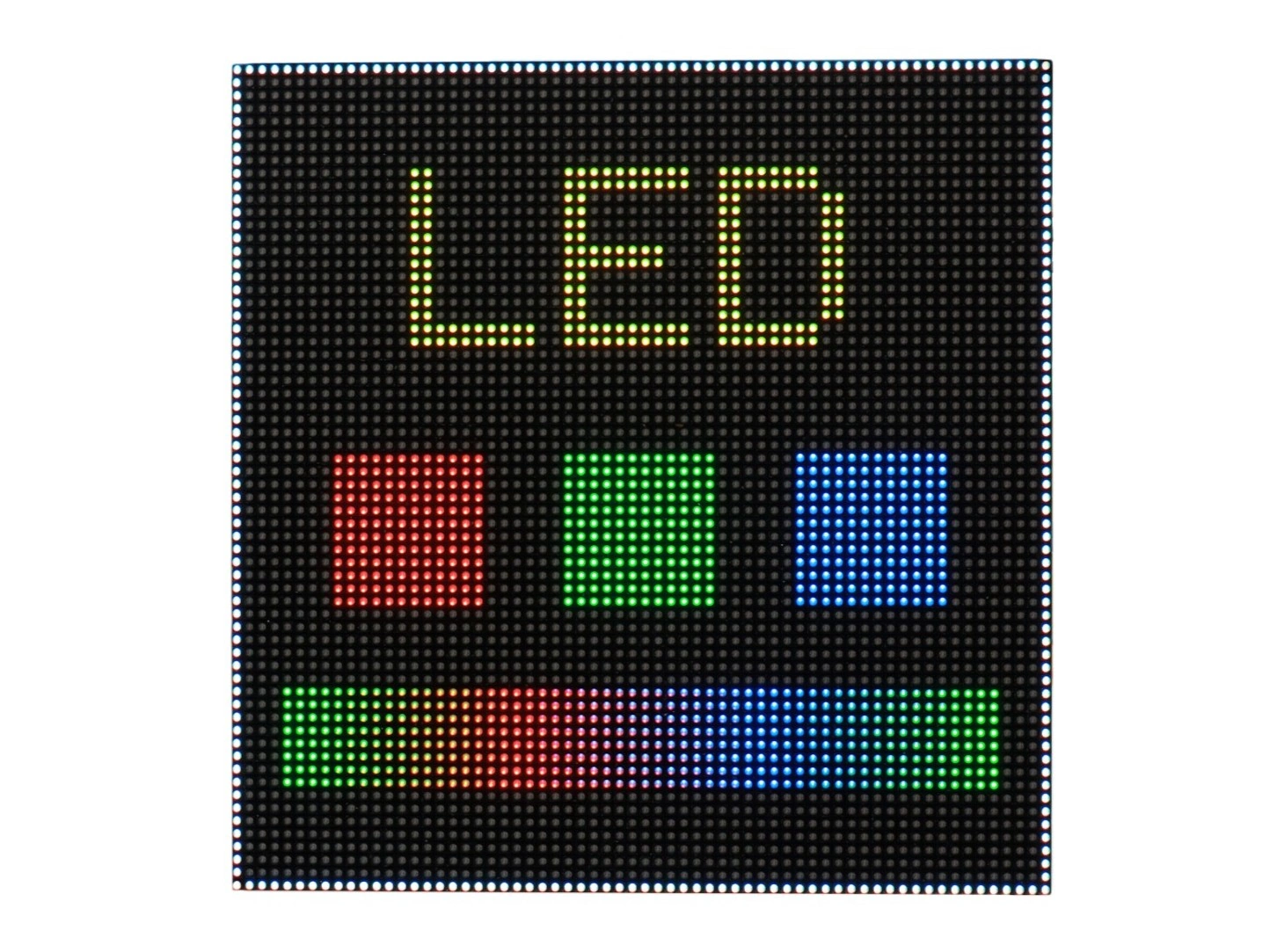
After uploading the following example, the panel shows, from top to bottom, a centered yellow LED title, red, green, and blue color blocks, and a rainbow gradient, all surrounded by a white border. The primary-color blocks verify the R/G/B channel wiring, and the gradient shows full-color transitions.
#include <ESP32-HUB75-MatrixPanel-I2S-DMA.h>

// 1. Display parameters: one 64×64 panel, no cascade
#define PANEL_RES_X 64   // Width of one panel in pixels
#define PANEL_RES_Y 64   // Height of one panel in pixels
#define PANEL_CHAIN 1    // Number of cascaded panels

MatrixPanel_I2S_DMA *dma_display = nullptr;

// 2. Gradient color: input 0–255, output a color cycling from green to red to blue
uint16_t colorWheel(uint8_t pos) {
  if (pos < 85) {
    return dma_display->color565(pos * 3, 255 - pos * 3, 0);
  } else if (pos < 170) {
    pos -= 85;
    return dma_display->color565(255 - pos * 3, 0, pos * 3);
  } else {
    pos -= 170;
    return dma_display->color565(0, pos * 3, 255 - pos * 3);
  }
}

void setup() {
  Serial.begin(115200);

  // 3. HUB75 pins: list the actual ESP32-S3-RGB-Matrix board connections in order
  HUB75_I2S_CFG::i2s_pins pins = {
    4, 5, 6,       // R1, G1, B1
    7, 15, 16,     // R2, G2, B2
    18, 8, 3, 42,  // A, B, C, D
    9,             // E: required for a 1/32-scan display
    40, 2, 41      // LAT, OE, CLK
  };

  // 4. Construct the configuration: panel width, panel height, cascade count, and pins
  HUB75_I2S_CFG mxconfig(PANEL_RES_X, PANEL_RES_Y, PANEL_CHAIN, pins);
  // This display uses conventional shift-register column drivers
  mxconfig.driver = HUB75_I2S_CFG::SHIFTREG;
  // Change the clock sampling edge; the default shifts the complete image by one pixel
  mxconfig.clkphase = false;

  // 5. Initialize and set brightness (0–255); higher brightness draws more current
  dma_display = new MatrixPanel_I2S_DMA(mxconfig);
  if (!dma_display->begin()) {
    Serial.println("HUB75 DMA buffer allocation failed.");
    while (true) {
      delay(1000);
    }
  }
  // 90 is an example value, not a universal brightness setting; check the 5 V supply current before increasing it.
  dma_display->setBrightness8(90);
  dma_display->clearScreen();

  // 6. White border around the edge of the display
  dma_display->drawRect(0, 0, PANEL_RES_X, PANEL_RES_Y,
                        dma_display->color565(255, 255, 255));

  // 7. Center the title at the top: at text size 2, each character is 12 pixels wide;
  //    "LED" is 36 pixels wide, so the starting x coordinate is (64 - 36) / 2 = 14
  dma_display->setTextSize(2);
  dma_display->setTextColor(dma_display->color565(255, 255, 0));
  dma_display->setCursor(14, 8);
  dma_display->print("LED");

  // 8. Three 12×12 primary-color blocks in the middle, evenly spaced with equal margins
  dma_display->fillRect( 8, 30, 12, 12, dma_display->color565(255, 0, 0));
  dma_display->fillRect(26, 30, 12, 12, dma_display->color565(0, 255, 0));
  dma_display->fillRect(44, 30, 12, 12, dma_display->color565(0, 0, 255));

  // 9. Rainbow gradient at the bottom: draw one vertical line per sampled color
  for (int x = 4; x < 60; x++) {
    uint8_t pos = (x - 4) * 255 / 55;
    dma_display->drawFastVLine(x, 48, 8, colorWheel(pos));
  }
}

void loop() {
  // Static image: DMA refreshes continuously in the background; no repeated drawing is required
}
Key points:
- Display parameters must match the physical display:
PANEL_RES_XandPANEL_RES_Yare the resolution of one panel.PANEL_CHAINis the number of panels cascaded horizontally on the same HUB75 data chain; use 1 for a single panel. Two 64×64 panels, for example, form a 128×64 logical canvas. For a 2×2, serpentine, or other two-dimensional arrangement, useVirtualMatrixPanelto map the coordinates. - Pin configuration must match the driver board: The 14 entries in
pinsmust remain in the fixed orderR1/G1/B1,R2/G2/B2,A/B/C/D,E,LAT/OE/CLK; do not rearrange them. This is a 1/32-scan display, so theEaddress line must be configured. If it is omitted, only half the image may appear or the image may be corrupted.driverandclkphaseare not pins:driver = SHIFTREGindicates conventional shift-register column drivers and is also the library default; specifying it makes the configuration explicit.clkphasecontrols the clock edge on which data is sampled. The library default istrue, but this display requiresfalse. With the default, the complete image shifts horizontally by one pixel, so the border is missing on one side and an extra column appears on the other. If another panel shows a similar horizontal shift or ghosting, this parameter is a useful place to start. - Check the return value of
begin(): It returnsfalseif DMA-buffer allocation fails. Increasing resolution, adding cascaded panels, increasing color depth, or enabling double buffering may leave insufficient internal RAM for the buffers. The screen then remains blank, and checking the return value identifies the problem directly through the serial output. - Brightness directly affects current:
setBrightness8()accepts 0–255. Higher brightness and more illuminated pixels increase current draw, so ensure the 5 V supply can provide enough current. The library also produces grayscale with the BCM dimming described under Display Principle; setting brightness too low reduces the available grayscale levels. - This example uses RGB565 color values: The Adafruit GFX-compatible interface represents colors as 16-bit RGB565 values.
color565(R, G, B)accepts three 0–255 channel values and converts them to RGB565. The library also provides functions such asdrawPixelRGB888()that accept RGB888 data directly, and color depth itself is configurable; when resources permit, the output can provide up to 8 bits per channel.colorWheel()maps a position from 0–255 to a repeating green→red→blue gradient, a common color-generation technique for LED-matrix demonstrations that is also useful for flowing rainbow animations. - Low-resolution layouts require pixel-accurate planning: A 64×64 canvas leaves little room. Check the coordinates and dimensions of every element. The default Adafruit GFX font occupies 6×8 pixels per character at size 1 and 12×16 at size 2. This example centers the title using 3 characters × 12 pixels = 36 pixels to calculate its starting coordinate. The margins around the color blocks and gradient are calculated in the same way to prevent overlap and keep the layout symmetrical.
- The drawing API matches Adafruit GFX:
drawRect(),fillRect(),drawFastVLine(),setCursor(), andprint()work the same way as in other Adafruit GFX-based libraries. - Do not refresh repeatedly in
loop(): Drawing calls write directly to the DMA buffer, and the hardware continuously sends that buffer to the display in the background. To create animation, update the buffer contents inloop(). If the animation flickers or tears, enable double buffering withmxconfig.double_buff = trueand callflipDMABuffer()after drawing each frame.
4.4 Troubleshooting
| Symptom | Common Cause | Solution |
|---|---|---|
| The display is completely dark | No 5 V supply; HUB75 ribbon cable is loose or reversed; begin() returned false | Check the display's 5 V supply; check the cable connection and orientation; inspect the serial output for a buffer-allocation failure |
| The image is dim, flickers, or looks red | The 5 V supply cannot provide enough current, or the power cable has excessive voltage drop | Use a higher-current 5 V supply or reduce brightness; use thicker power wires |
| Content in the upper and lower halves is misaligned or colors are corrupted | The scan ratio or pin configuration does not match the display | Check the display's scan ratio; verify PANEL_RES_Y and every pin assignment |
| The complete image is shifted or clipped | PANEL_RES_X/Y or the cascade count is incorrect | Correct the resolution and PANEL_CHAIN to match the physical display |
| Some rows remain dark | Address-line (A/B/C/D/E) wiring or configuration is incorrect | Check the address lines; the 64×64, 1/32-scan display in this example requires E |
| Pixels are shifted horizontally or ghosted | Clock phase is incorrect; blanking during latch transitions is insufficient | Toggle mxconfig.clkphase (this display requires false); use setLatBlanking() to adjust blanking if necessary |
| Geometry is correct, but colors are tinted incorrectly | R/G/B pin order is incorrect | Check the R1/G1/B1 and R2/G2/B2 pins |