OLED
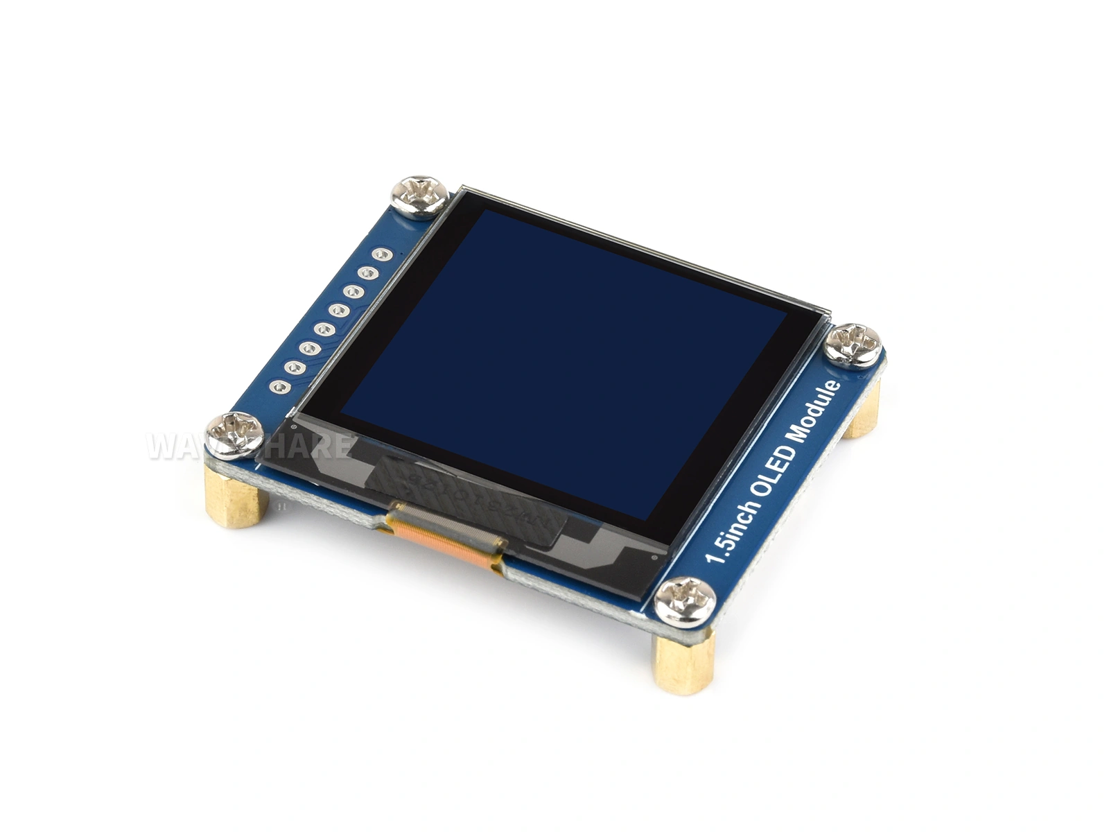
Each pixel in an OLED (organic light-emitting diode) display produces its own light, so the panel requires no backlight.
Embedded projects commonly use small 0.96–1.5-inch monochrome OLED modules. They require few connections, consume little power, and provide high contrast, making them a practical choice for status information and introductory projects.
This page explains how OLEDs work, introduces common controllers, and uses u8g2, the de facto standard graphics library for monochrome embedded displays.
1. Operating Principle
Each OLED pixel is a microscopic organic LED whose brightness varies with current. This is fundamentally different from an LCD's backlight and light-valve structure:

- An unlit pixel is truly black. An LCD backlight remains on and some light leaks through a black pixel. An OLED black pixel is unpowered, producing high contrast and deep black.
- Power depends on image content. More illuminated pixels and greater brightness increase consumption. Dark interfaces consume relatively little power.
OLED panels use one of two addressing methods:
- PMOLED (passive-matrix OLED): Pixels share row and column electrodes, and only one row is driven at a time. Rapid row scanning produces a complete image through persistence of vision. As row count increases, each row receives less on-time and needs greater peak current to maintain brightness. This limits practical size and resolution, so most PMOLED products are below 3 inches. The compact modules discussed on this page are PMOLEDs.
- AMOLED (active-matrix OLED): Each pixel has its own TFT (thin-film transistor) circuit and can remain illuminated continuously. This supports larger, higher-resolution, full-color panels. See AMOLED.
PMOLED is the default for compact monochrome modules and may not be called out explicitly. AMOLED is generally identified in the product name or by its controller.
2. Advantages and Limitations
Advantages:
- High contrast, deep black, and clear small text.
- Self-emissive pixels and wide viewing angles.
- Fast response with little motion blur.
- Low power for dark content because black pixels are off.
- Simple module interfaces; I2C requires only SDA and SCL.
Limitations:
- Compact sizes and low resolutions. Common modules range from 0.42 to 2.42 inches, with 0.96–1.5 inches and approximately 128×64 pixels being most common.
- Usually monochrome in white, blue, or yellow. Some modules provide two colors or grayscale; full-color PMOLED is uncommon.
- Risk of burn-in: Organic material degrades with cumulative illumination time. Avoid displaying completely static content indefinitely; periodically move content, reduce brightness, or turn off the panel.
- Moderate readability in direct sunlight.
3. Common Controllers and Interfaces
| Controller | Resolution | Characteristics | Typical display |
|---|---|---|---|
| SSD1306 | 128×64 | Most common and extensively documented | 0.91 / 0.96 inch |
| SH1106 | 128×64 | Similar to SSD1306, but GRAM is 132 columns wide—four columns wider than the visible area. Using an SSD1306 constructor shifts the image. | 1.3 inch |
| SSD1309 | 128×64 | Similar to SSD1306 and often used in larger monochrome modules | 2.42 inch |
| SSD1327 | 128×128 | 16 grayscale levels | 1.5 inch |
These controllers support both I2C and SPI, but a module exposes the interface selected by its board design. Some Waveshare modules use solder-jumper resistors to switch interfaces; check the corresponding product page for the factory-default interface. Other modules are fixed to one interface at manufacture.
- I2C: Requires only SDA and SCL and can share the bus with other devices. Its lower bandwidth limits complete-screen refresh rate.
- SPI: Uses DIN, CLK, CS, DC, and RST but is substantially faster and better suited to animation.
The 1-bpp GRAM in controllers such as SSD1306 and SH1106 uses page addressing: each page is eight pixel rows high, and one byte represents eight vertically adjacent pixels in a column. A grayscale SSD1327 instead uses 4 bpp, storing two adjacent pixel values in each byte. See Color Depth for the bpp notation. u8g2 maintains its own draw buffer and converts it to the controller-specific layout during transfer, so application code does not need to manage these formats.

4. Arduino and u8g2 Example
u8g2 supports nearly every common monochrome controller, including SSD1306, SH1106, and SSD1327, and includes hundreds of fonts. The RLCD example also uses u8g2.
This example uses the Waveshare 1.5inch OLED Module. It has an SSD1327 controller, 128×128 resolution, and 16 grayscale levels. u8g2 drives it as a black-and-white display, as explained below. The I2C connection can be used with any ESP32 board. For another module, change the pins and constructor.
4.1 Constructors and Buffer Modes
u8g2 selects the controller, module, buffer mode, and interface through its constructor class name:
U8G2_<controller>_<module>_<buffer mode>_<interface>
For example, U8G2_SSD1327_WS_128X128_F_HW_I2C specifies an SSD1327, a Waveshare (WS) 128×128 module, full-buffer mode (F), and hardware I2C. Matching the constructor to the exact module is the most important step when using u8g2. Two modules using the same controller can require different initialization parameters, GRAM offsets, or scan directions. If no exact entry exists, begin with a constructor using the same controller and resolution and verify the result. See the u8g2 setup reference.
| Mode | Code | Memory for 128×64 | Drawing pattern |
|---|---|---|---|
| Full buffer | F | Complete 1 KB frame | Draw freely, then call sendBuffer() |
| Page buffer | 1 / 2 | 128 / 256 bytes | Repeat drawing inside a firstPage()/nextPage() loop |
Page buffers target very small microcontrollers such as AVR devices. ESP32 has enough memory to use a full buffer in this example.
u8g2 is a 1-bpp graphics library. Calls such as drawStr() and drawBox() distinguish only on and off. Although SSD1327 supports 16 grayscale levels in 4-bpp GRAM, u8g2 maps an on pixel to maximum intensity. To render gradients or antialiased grayscale text, write the SSD1327's 4-bpp GRAM directly or use a library with a grayscale framebuffer.
4.2 Install the Library
Search for and install U8g2 in Library Manager. See Installing Arduino Libraries for other methods.
4.3 Confirm the Pins
The Waveshare 1.5inch OLED Module ships in 4-wire SPI mode, with BS1 and BS2 connected to GND. Before using the I2C wiring and code below, move the BS1 and BS2 resistor links to VCC as shown on the product Wiki. DIN then becomes SDA and CLK becomes SCL; CS and DC remain disconnected. The default I2C address is 0x3D. BS3 selects 0x3C when connected to GND.
This example uses the Waveshare ESP32-S3-Zero and matches the wiring in Arduino I2C Communication:
| Development-board pin | OLED module | Description |
|---|---|---|
| GPIO 1 | DIN (SDA) | I2C data |
| GPIO 2 | CLK (SCL) | I2C clock |
| 3.3V | VCC | Positive supply |
| GND | GND | Ground |
On another ESP32 board, select available I2C pins and update SDA_PIN and SCL_PIN. Avoid pins assigned to flash, PSRAM, boot configuration, or onboard peripherals. Using the default UART pins also interferes with serial output.
4.4 Example Code
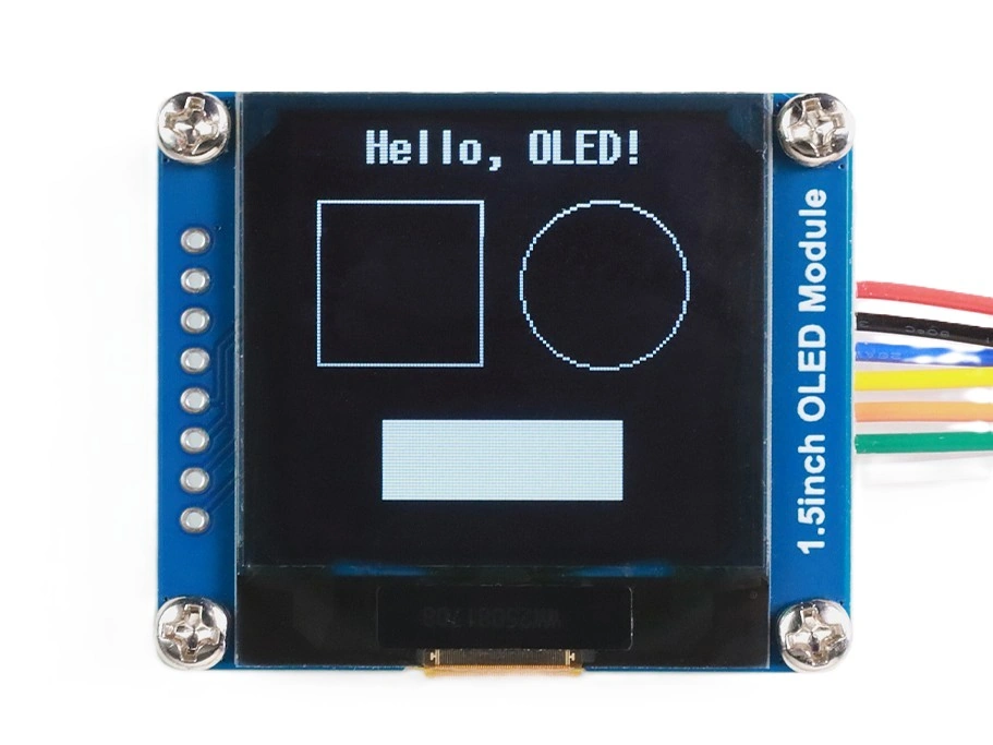
After uploading the following example, the module shows, from top to bottom, a centered title, an outlined rectangle and circle, and a filled rectangle, separated by blank space.
#include <U8g2lib.h>

#define SDA_PIN 1
#define SCL_PIN 2

// 1. SSD1327, Waveshare 128×128, full buffer, hardware I2C.
//    U8G2_R0 means no rotation. ESP32 pins can be passed here.
U8G2_SSD1327_WS_128X128_F_HW_I2C u8g2(U8G2_R0, /* reset= */ U8X8_PIN_NONE,
                                      /* clock= */ SCL_PIN, /* data= */ SDA_PIN);

void setup() {
  // 2. The module defaults to 0x3D. u8g2 expects the 8-bit address.
  u8g2.setI2CAddress(0x3D << 1);
  u8g2.begin();

  // 3. Clear the buffer.
  u8g2.clearBuffer();

  // 4. Center the title using its measured width.
  u8g2.setFont(u8g2_font_7x14B_tr);
  const char *title = "Hello, OLED!";
  int titleW = u8g2.getStrWidth(title);
  u8g2.drawStr((128 - titleW) / 2, 13, title);

  // 5. Draw an outline and circle side by side.
  u8g2.drawFrame(8, 24, 50, 50);
  u8g2.drawCircle(94, 49, 25);

  // 6. Draw a filled rectangle.
  u8g2.drawBox(28, 90, 72, 24);

  // 7. Transfer the buffer.
  u8g2.sendBuffer();
}

void loop() {
  // Static image; no repeated refresh is required.
}
Key points:
- Draw first, then call
sendBuffer(): Drawing calls modify the memory buffer. The standard update sequence isclearBuffer()→ draw →sendBuffer(). - The font controls text size and does not wrap or scale automatically: In
u8g2_font_7x14B_tr,7x14gives the approximate character dimensions. A 128-pixel row fits about 18 characters of this font. See the u8g2 font list. - Measure text with
getStrWidth(): Proportional fonts vary by character. Measure the string before calculating its starting coordinate. - I2C address: This module defaults to
0x3D. If initialization produces no image, run the I2C scanner to verify the address.
4.5 Troubleshooting
| Symptom | Likely cause | Corrective action |
|---|---|---|
| No image | Wrong I2C address or wiring | Scan the bus and check SDA/SCL |
| Image shifted by two pixels or noisy edge | SH1106 module using an SSD1306 constructor | Use the SH1106 constructor |
| Only part of the image appears | Page-buffer constructor without a firstPage()/nextPage() loop | Use a full-buffer (F) constructor or the page loop |
| Text missing | sendBuffer() or setFont() omitted | Follow clear → draw → send and set the font |
| Text clipped or overlapping shapes | Coordinates do not account for actual font size | Measure with getStrWidth() and leave adequate spacing |
| Persistent image after prolonged use | Burn-in | Avoid leaving completely static content on indefinitely |