RLCD
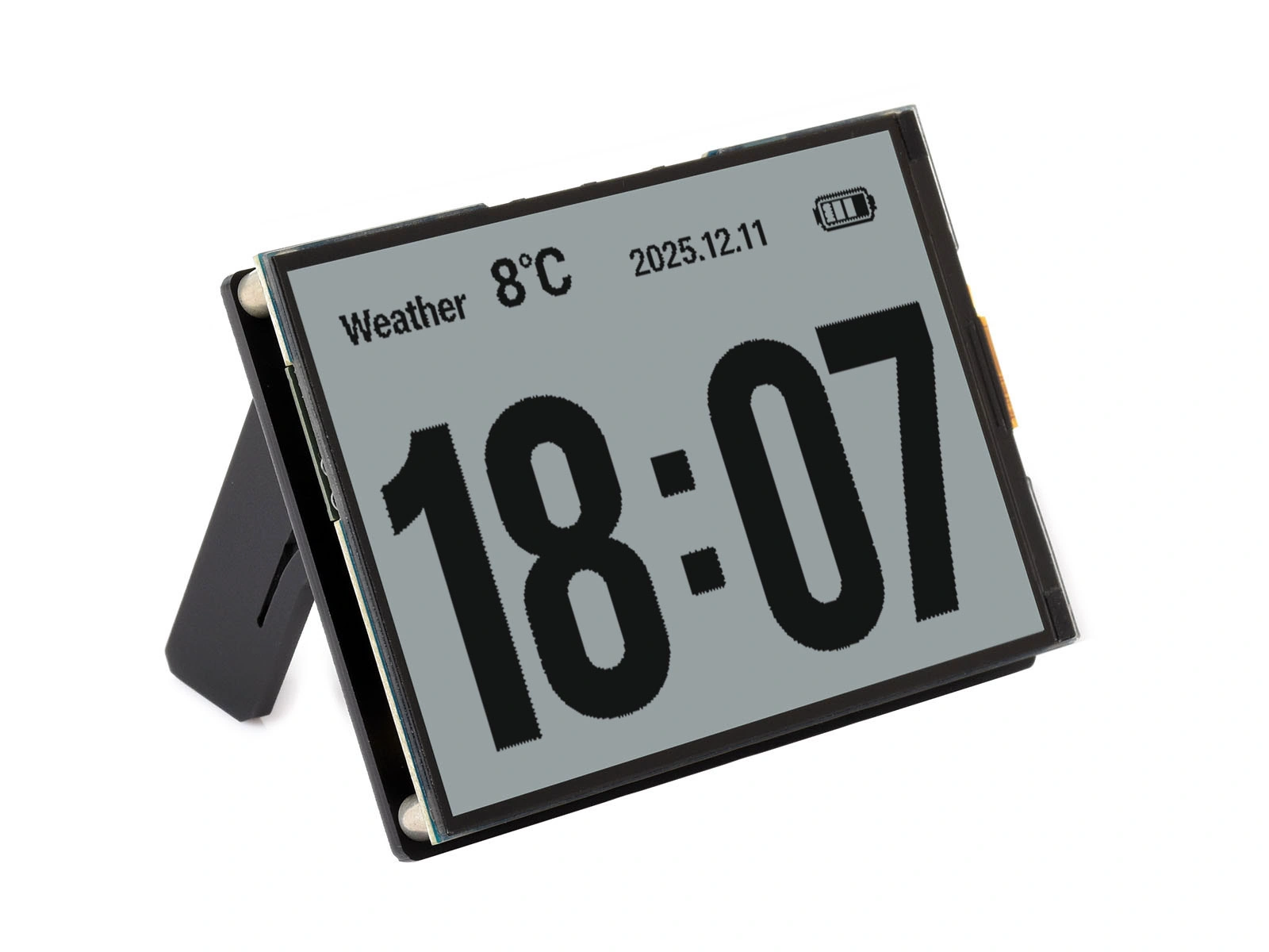
An RLCD (reflective liquid-crystal display) is an LCD that reflects ambient light instead of using a backlight. Its appearance is similar to e-paper, but its refresh rate is comparable to a conventional LCD. RLCD is suited to applications that need e-paper-like power consumption and sunlight readability together with real-time updates, such as always-on clocks, electronic calendars, and outdoor instruments.
Read the LCD operating-principle section first. Both technologies use liquid crystals to control light.
1. Operating Principle
Both transmissive and reflective LCDs use the liquid-crystal layer as a light valve. The difference is the source of the light:
- Transmissive LCD: Light comes from a backlight beneath the panel and passes once through the liquid-crystal layer.
- Reflective LCD: A reflector replaces the backlight. Ambient light enters from the front, passes through the liquid crystals, reflects, and passes through the layer again. A transmitting pixel reflects light and appears bright; a blocking pixel appears dark.

This has two immediate consequences:
- The display becomes clearer as ambient light increases. Direct sunlight can overpower the backlight of a conventional LCD, while it gives an RLCD its best readability.
- The display cannot be seen without ambient light. It requires external illumination in the dark. Some products add an optional front light.
An RLCD has no backlight and does not emit light like a conventional LCD. A relatively dim appearance is normal and does not indicate a fault. Readability improves with ambient light, and the lack of a backlight can reduce eye strain during prolonged use.
Low-power RLCD products commonly use one of two technologies:
- Low-power reflective LCD using a TFT backplane: The TFT (Thin Film Transistor) backplane works with the display controller to reduce power when the image is unchanged while retaining fast updates.
- Memory-in-Pixel (MIP): Each pixel contains a 1-bit storage element and uses almost no power to retain an image. Sharp Memory LCDs used in outdoor sports watches are a common example.
2. Advantages and Limitations
Advantages:
- Very low power: Removing the backlight cuts static display power by one or two orders of magnitude compared with a conventional LCD, making RLCD suitable for battery-powered always-on devices.
- Fast updates: Millisecond liquid-crystal response supports animation and real-time data. Unlike e-paper, RLCD does not suffer from e-paper ghosting.
- Sunlight readability: A reflective image becomes clearer in stronger light.
- Paper-like viewing: No backlight shines toward the viewer.
Limitations:
- Depends on ambient light: A front light or external illumination is required in the dark.
- Limited color: Most current panels are monochrome, and color RLCDs are less saturated than conventional LCDs.
- Moderate contrast: Reflective efficiency limits contrast compared with e-paper and OLED.
- Fewer sizes and drivers are available than for conventional LCDs.
| Requirement | Better-suited technology |
|---|---|
| Full-color indoor GUI | LCD / AMOLED |
| Nearly static image and maximum standby time (price tags and calendar covers) | E-paper |
| Always-on, real-time updates, outdoor readability, and battery power | RLCD |
3. Drivers and Interfaces
To a microcontroller, an RLCD resembles an SPI LCD. Its controller includes GRAM (see Display Fundamentals and Interfaces), receives commands and pixels over SPI, and follows the reset, initialization, write-window, and pixel-transfer sequence described in that page.
The main difference is pixel format. Monochrome RLCD GRAM uses 1 bpp (1 bit per pixel; see Color Depth). One 300×400 frame occupies only 300 × 400 ÷ 8 = 15000 bytes, compared with 240000 bytes for RGB565 at the same resolution. SPI can therefore achieve a high frame rate while retaining low power consumption.
Sitronix ST7305 and ST7306 are examples of low-power reflective-LCD controllers that support low-power modes and window updates. Waveshare board examples already encapsulate the controller layer, so applications normally do not access these registers directly.
3.1 Graphics Library
u8g2 is the recommended library for a monochrome RLCD. Its 1-bpp buffer matches the panel's native format, and it provides extensive fonts and drawing functions.
LVGL can also be ported in monochrome mode when a more complex interface is required.
4. Arduino and u8g2 Example
This example uses the Waveshare ESP32-S3-RLCD-4.2, which includes a 4.2-inch 300×400 fully reflective ST7305 panel. For another board or module, change the pin definitions and constructor.
4.1 Preparation
- Install the Arduino IDE and ESP32 board support as described in Arduino IDE Setup.
- Search for and install
U8g2in Library Manager. See Installing Arduino Libraries for other installation methods. - Configure the board as described on the product's Arduino page.
| Package | Version requirement |
|---|---|
| arduino-esp32 | v3.3.0 or later |
| U8g2 | v2.36.19 or later, including support for the 300×400 ST7305 panel |
4.2 Confirm the Pins
The display is connected directly to the microcontroller. Unlike a conventional LCD, it has no BL pin:
| Signal | GPIO | Description |
|---|---|---|
| RLCD_SCK | GPIO11 | SPI clock |
| RLCD_MOSI | GPIO12 | SPI data |
| RLCD_DC | GPIO5 | Command/data selection |
| RLCD_CS | GPIO40 | Chip select |
| RLCD_RST | GPIO41 | Reset |
4.3 Example Code
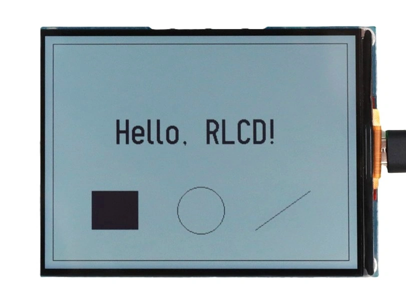
U8g2 supports the ST7305 natively through the U8G2_ST7305_300X400 constructors. ESP32-S3 can route hardware SPI to these pins, so the example uses 4W_HW_SPI. After building and uploading the following example, the display shows “Hello, RLCD!” and several shapes. RLCD forms its image from ambient light, so view it in good ambient light.
#include <U8g2lib.h>
#include <SPI.h>

// Pin definitions for ESP32-S3-RLCD-4.2
#define RLCD_SCK  11
#define RLCD_MOSI 12
#define RLCD_DC   5
#define RLCD_CS   40
#define RLCD_RST  41

// 1. Create the display object: ST7305, 300×400, hardware SPI.
//    U8G2_R1 rotates the logical display to 400×300 landscape.
//    Arguments: rotation, CS, DC, RST.
U8G2_ST7305_300X400_F_4W_HW_SPI u8g2(U8G2_R1, RLCD_CS, RLCD_DC, RLCD_RST);

void setup() {
  // 2. Route hardware SPI to SCK=11 and MOSI=12.
  //    MISO is unused, so pass -1.
  SPI.begin(RLCD_SCK, -1, RLCD_MOSI, RLCD_CS);

  // 3. Initialize the display.
  u8g2.begin();

  // 4. Clear the buffer.
  u8g2.clearBuffer();

  // 5. Draw text.
  u8g2.setFont(u8g2_font_logisoso32_tf);
  u8g2.drawStr(90, 140, "Hello, RLCD!");

  // 6. Draw an outline and shapes.
  u8g2.drawFrame(10, 10, 380, 280);
  u8g2.drawBox(60, 200, 60, 50);
  u8g2.drawCircle(200, 225, 30);
  u8g2.drawLine(270, 250, 340, 200);

  // 7. Transfer the buffer to the display.
  u8g2.sendBuffer();

  // 8. The image no longer changes, so switch to low power mode (LPM).
  //    This constructor already configures the required source voltages.
  u8g2.sendF("c", 0x39);
  delay(100);  // Wait for the mode switch to complete.
}

void loop() {
}
u8g2 constructor names follow U8G2_<controller>_<resolution>_<buffer mode>_<bus type>. U8G2_ST7305_300X400_F_4W_HW_SPI specifies an ST7305 at 300×400, full-frame buffer mode F, and 4-wire hardware SPI. Rotation, CS, DC, and RST follow the constructor name.
- Buffer mode:
Fbuffers a complete frame. Modes1and2buffer one or two tile rows and use afirstPage()/nextPage()loop. They use less memory but require a different drawing pattern. A 300×400 1-bpp frame is only 15000 bytes, so a full buffer is practical on ESP32-S3. - Bus type:
4W_HW_SPIuses the hardware SPI peripheral. Use4W_SW_SPIonly when software-generated SPI on arbitrary pins is required.
See the u8g2 setup reference for the complete naming scheme.
The hardware-SPI constructor accepts CS, DC, and RST; SCK and MOSI are assigned through the SPI peripheral. The board connects SCK to GPIO11 and MOSI to GPIO12 rather than the default FSPI pins, so call SPI.begin(11, -1, 12, 40) before u8g2.begin(). Otherwise, the display receives no data.
Routing SPI through the GPIO matrix instead of the dedicated IO MUX reduces the approximate maximum clock from 80 MHz to 40 MHz, but the hardware peripheral still generates the signals. The ST7305 datasheet specifies a minimum write-clock period of 30 ns, or approximately 33 MHz. This example uses no more than 24 MHz, so neither limit is reached.
Low power mode: The ST7305 defines a high power mode (HPM, command 0x38) and a low power mode (LPM, command 0x39). The modes differ in panel self-refresh frequency. This constructor's initialization sequence sets HPM to 32 Hz and LPM to 1 Hz.
Once a static image has been written to the frame memory, the controller can switch to LPM without affecting the displayed content. The switching sequence in the datasheet also includes changing the source voltage group, but this constructor's initialization sequence already configures the source voltages this panel requires, so that step can be omitted. The example therefore sends only the mode command with sendF("c", 0x39) and then waits as the datasheet requires. U8g2 does not wrap the HPM and LPM commands; sendF("c", ...) sends command bytes directly to the controller.
To update the image again, switch back to HPM with sendF("c", 0x38), draw, call sendBuffer(), and return to LPM afterwards. Writing while in LPM can delay the visible update by up to one refresh period, approximately one second.
For other frame-rate settings and the complete HPM/LPM switching timing requirements, see the ST7305 datasheet.
Other common u8g2 functions include:
u8g2.drawUTF8(x, y, "text");           // Draw a UTF-8 string.
u8g2.drawDisc(x, y, r);                // Draw a filled circle.
u8g2.drawXBMP(x, y, w, h, bitmap);     // Draw a monochrome bitmap.
u8g2 writes all drawing operations to memory first. sendBuffer() transfers the completed buffer to the display, matching the framebuffer concept described in Display Fundamentals and Interfaces.
4.4 Dynamic Refresh Example
RLCD supports continuous refresh in HPM. The following version reuses the hardware-SPI configuration from Section 4.3, moves the drawing code into loop(), and measures its frame rate. It stays in HPM because the image changes continuously and never switches to LPM. After building and uploading the example, the counter at the center of the display updates continuously and the frame rate appears at the bottom, at approximately 45 FPS:
#include <U8g2lib.h>
#include <SPI.h>

// Pin definitions for ESP32-S3-RLCD-4.2
#define RLCD_SCK  11
#define RLCD_MOSI 12
#define RLCD_DC   5
#define RLCD_CS   40
#define RLCD_RST  41

// Hardware SPI constructor: rotation, CS, DC, RST.
U8G2_ST7305_300X400_F_4W_HW_SPI u8g2(U8G2_R1, RLCD_CS, RLCD_DC, RLCD_RST);

uint32_t counter = 0;
uint32_t lastMs = 0;
uint32_t frames = 0;
uint32_t fps = 0;

void setup() {
  // Route hardware SPI to SCK=11 and MOSI=12.
  SPI.begin(RLCD_SCK, -1, RLCD_MOSI, RLCD_CS);

  u8g2.begin();
  u8g2.setBusClock(24000000);  // Use a 24 MHz SPI clock.
  lastMs = millis();
}

void loop() {
  char buf[32];

  u8g2.clearBuffer();

  // Draw the counter in the center.
  u8g2.setFont(u8g2_font_logisoso50_tn);
  snprintf(buf, sizeof(buf), "%lu", (unsigned long)counter);
  int w = u8g2.getStrWidth(buf);
  u8g2.drawStr((400 - w) / 2, 170, buf);

  // Draw the measured frame rate.
  u8g2.setFont(u8g2_font_6x13_tf);
  snprintf(buf, sizeof(buf), "FPS: %lu", (unsigned long)fps);
  u8g2.drawStr(20, 285, buf);

  u8g2.drawFrame(10, 10, 380, 280);

  u8g2.sendBuffer();

  counter++;
  frames++;

  // Update the measurement once per second.
  uint32_t now = millis();
  if (now - lastMs >= 1000) {
    fps = frames * 1000 / (now - lastMs);
    frames = 0;
    lastMs = now;
  }
}
Compared with the first example, this version calls setBusClock(24000000) after u8g2.begin() and redraws from loop(). The constructor, pin routing, and drawing API are unchanged.
The example measures how often sendBuffer() is called, which is the frequency at which the host writes complete frames into the controller's frame memory. It is not the panel's self-refresh frequency. With this constructor's initialization, the panel self-refreshes at 32 Hz in HPM, as described in Example Code. Writing faster than that does not raise the panel's self-refresh frequency.
4.5 Troubleshooting
| Symptom | Likely cause | Corrective action |
|---|---|---|
| Display is difficult to see in the dark | RLCD requires ambient light | Add external illumination |
| Constructor does not compile | U8g2 version predates ST7305 support | Upgrade U8g2 to the minimum version listed in Preparation |
| Shifted or corrupted image | Wrong resolution or rotation constructor | Select the 300×400 ST7305 constructor and the intended rotation |
Display goes blank after calling setPowerSave(1) | That function sends the 0x28 display-off command and does not switch the ST7305 into LPM | Call setPowerSave(0) to restore the image; use sendF("c", 0x39) when LPM is required |