Working with Arduino
ESP32-S3 Applications
Camera
This example is modified from the official ESP32 CameraWebServer example to adapt it for the ESP32-S3 platform.
-
Set the Wi-Fi SSID and password, and switch the default hardware to ESP32-S3
-
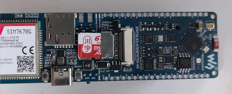
Turn on the CAM DIP switch on the back of the board and connect a supported camera
-
Confirm the Camera pin definitions as follows:
Pin Definition V1 Version V2 Version 


#define PWDN_GPIO_NUM-1 -1 #define RESET_GPIO_NUM-1 -1 #define XCLK_GPIO_NUM34 39 #define SIOD_GPIO_NUM15 15 #define SIOC_GPIO_NUM16 16 #define Y9_GPIO_NUM14 14 #define Y8_GPIO_NUM13 13 #define Y7_GPIO_NUM12 12 #define Y6_GPIO_NUM11 11 #define Y5_GPIO_NUM10 10 #define Y4_GPIO_NUM9 9 #define Y3_GPIO_NUM8 8 #define Y2_GPIO_NUM7 7 #define VSYNC_GPIO_NUM36 42 #define HREF_GPIO_NUM35 41 #define PCLK_GPIO_NUM37 46 -
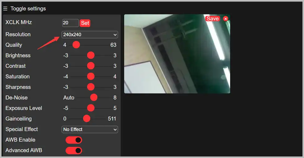
After flashing the program, open the serial terminal. Access the IP address output by the serial monitor in a browser to view the camera feed, as shown in the following figure:
TF-Card
-
Insert the TF-Card into the TF card slot
-
Define the pins
const int SDMMC_CLK = 5;const int SDMMC_CMD = 4;const int SDMMC_DATA = 6;const int SD_CD_PIN = 46; -
Flash the program and open the terminal to display the file contents

RGB
This development board is equipped with one WS2812B RGB LED. The signal pin is GPIO38. After flashing the example program, the RGB LED will display a gradient effect, as shown in the following figure:
BAT
This development board uses the MAX17048 as the battery fuel gauge IC.
-
Confirm the I2C pin connections. There are differences in IO connections between the V1 and V2 versions:
MAX17048 Pin Version SDA SCL Initialization Code ESP32-S3 IO V1 Version GPIO3 GPIO2 Wire.begin(3, 2) ESP32-S3 IO V2 Version GPIO15 GPIO16 Wire.begin(15, 16) -
Flash the example program. The battery alert threshold can be modified as needed

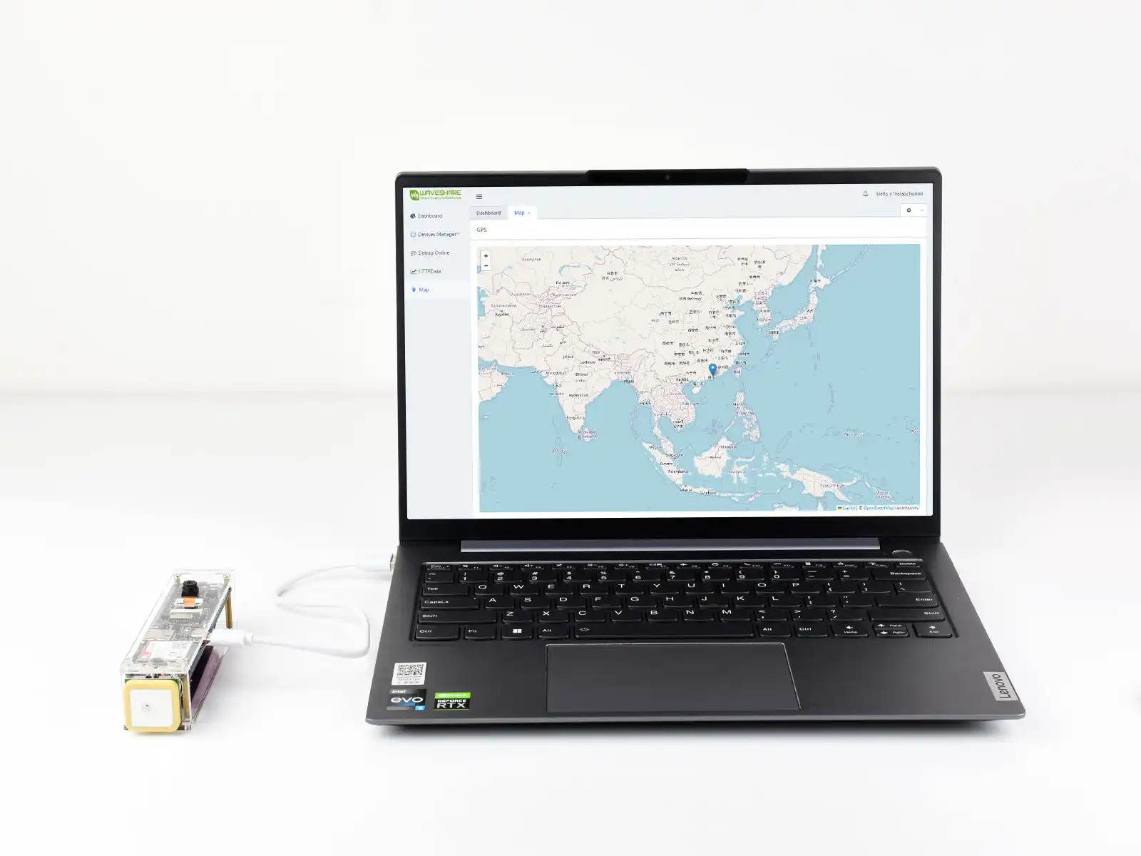
Waveshare Cloud Application
This application communicates with the A7670E via the ESP32-S3 software serial. It sends AT commands to enable GNSS, parses the NMEA GNSS data, and uploads it to Waveshare Cloud. The specific location of the development board is then displayed on a map page using a Web View.
- Please download the demo, unzip it, and open the GNSS-With-WaveshareCloud example code.
- The map service provided by Waveshare Cloud is used here for demonstration
Configuration Steps
-
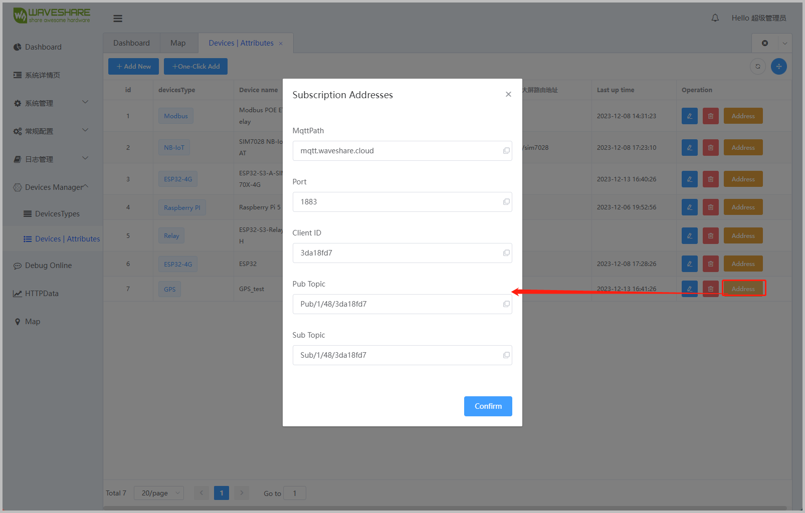
Go to the Devices | Attributes page, create a device of any type, and obtain the corresponding MQTT connection parameters.
-
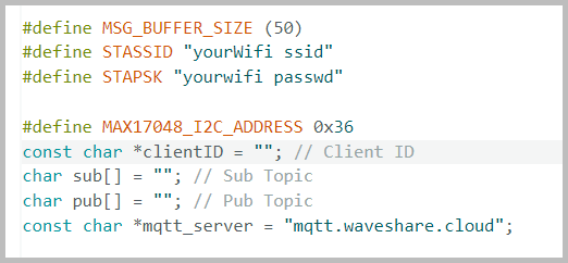
Fill in the obtained MQTT parameters into the GNSS-With-WaveshareCloud example program.
-
Compile and flash the program. You can then view the real-time location information of the development board on the Waveshare Cloud map page.