Working with ESP-IDF
This chapter contains the following sections. Please read as needed:
- ESP-IDF Getting Started
- Setting Up Development Environment
- Running Official Espressif Demos
- Location and Network Communication Demos
ESP-IDF Getting Started
New to ESP32 ESP-IDF development and looking to get started quickly? We have prepared a general Getting Started Tutorial for you.
- Section 1: Environment Setup
- Section 2: Running Examples
- Section 3: Creating a Project
- Section 4: Using Components
- Section 5: Debugging
- Section 6: FreeRTOS
- Section 7: Peripherals
- Section 8: Wi-Fi Programming
- Section 9: BLE Programming
Please Note: This tutorial uses the ESP32-S3-Zero as a teaching example, and all hardware code is based on its pinout. Before you start, it is recommended that you check the pinout of your development board to ensure the pin configuration is correct.
Setting Up Development Environment
The following tutorial is based on the Windows development environment using VS Code.
ESP-IDF has supported ESP32-S3 since version v4.3. For full functionality and development stability, it is recommended to use v4.4 or later, with v5.1+ preferred for new projects.
Please refer to the Waveshare ESP-IDF Getting Started - Section 1 Set Up Environment to complete the ESP-IDF development environment configuration.
Running Official Espressif Demos
Create Demo
-
Use the F1 shortcut key, then enter
ESP-IDF: Show Examples Projectsin the command palette ----------------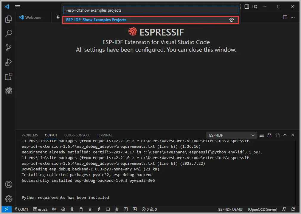
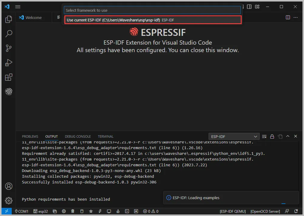
-
Select the IDF version that matches your current ESP-IDF environment (it is recommended to choose the version shown in the status bar or the current terminal)
-
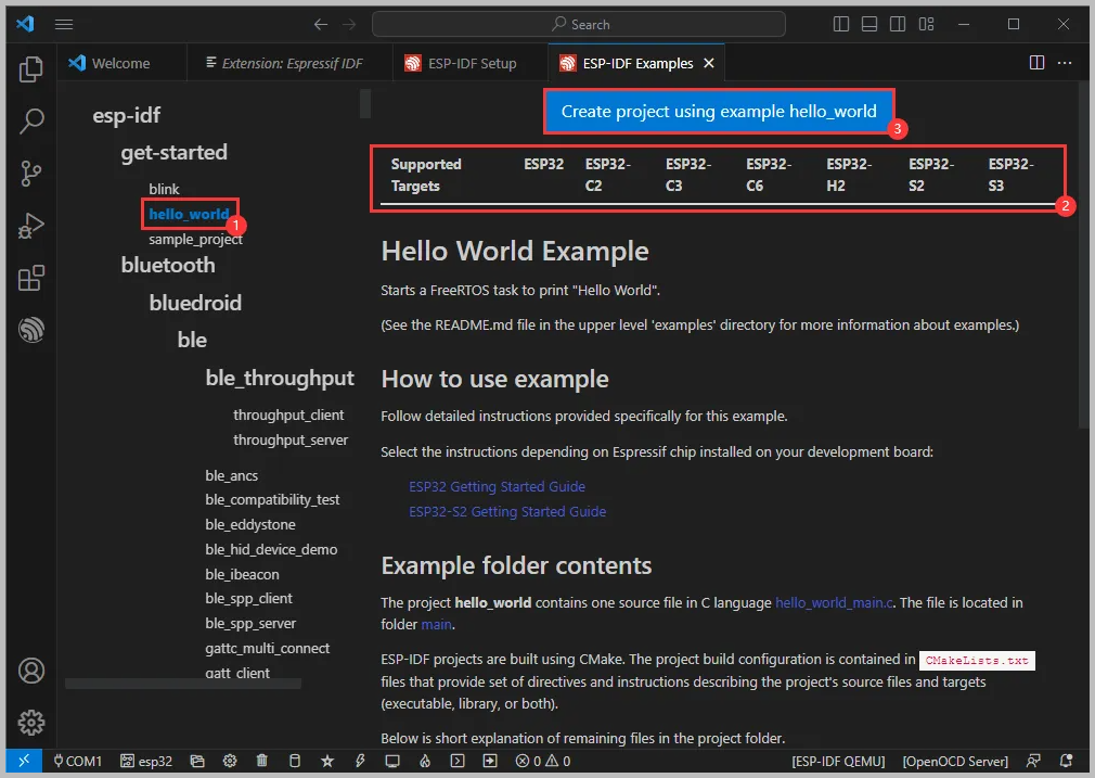
Take the Hello world demo as an example
-
① Select the corresponding demo
-
② Its readme will state what chip the demo applies to (how to use the demo and the file structure are described below, omitted here)
-
③Click to create the demo
-
-
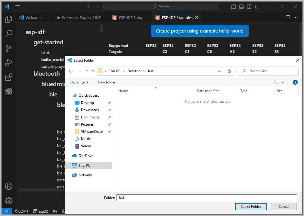
Choose a path to place the demo, ensuring there is no folder with the same name as the demo
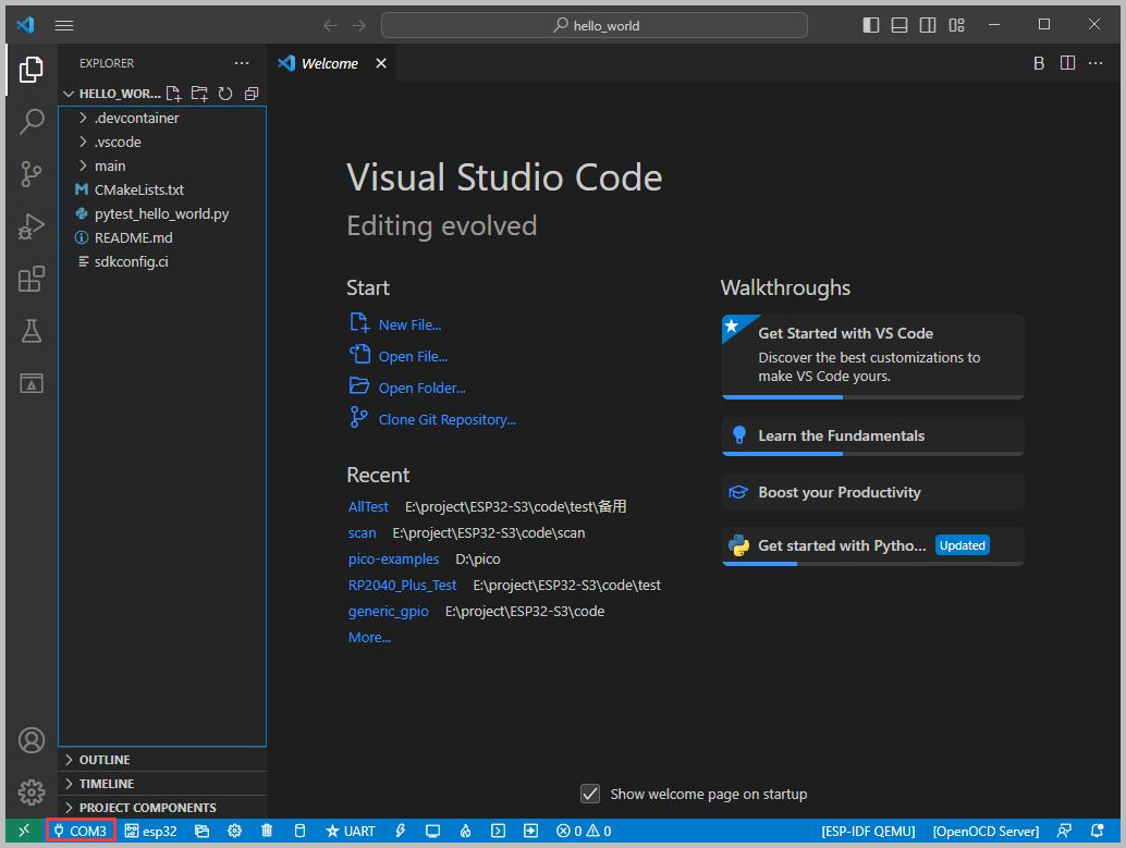
Modify COM Port
-
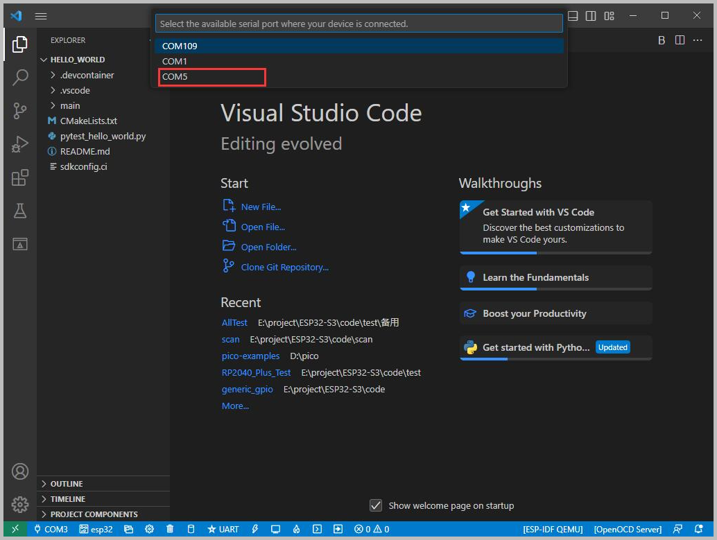
This shows the currently used COM port. Click to modify the corresponding COM port.
-
This development board features an onboard USB-to-serial chip, the CH343. It may be enumerated as different COM ports on different computers. Please select the COM port based on what is actually shown in the "Device Manager"
-
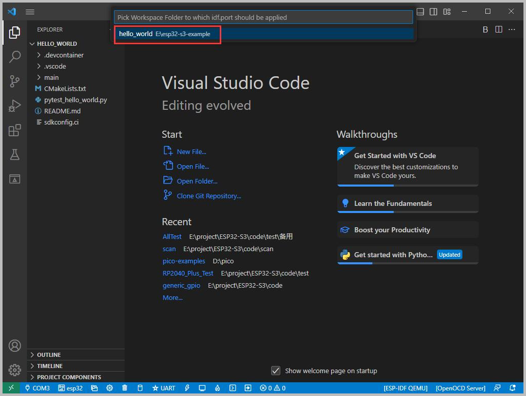
Select the project or demo to use
-
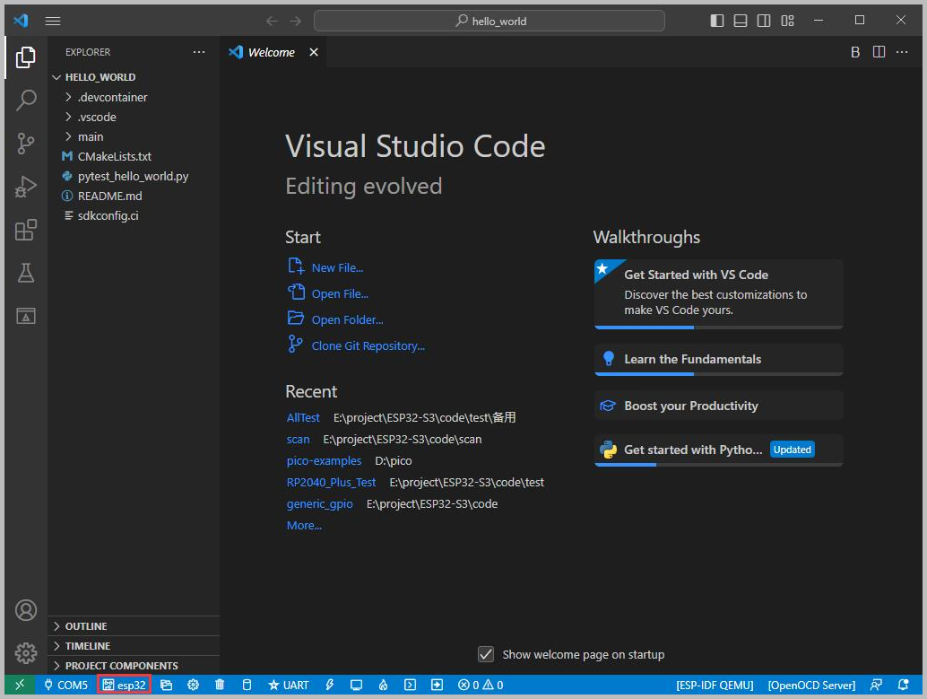
After modification, the new COM port will be displayed in the status bar
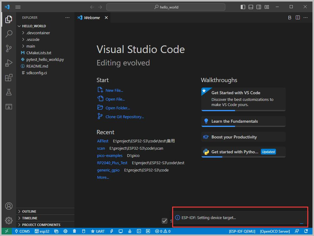
Select Target Chip
-
This shows the currently used target chip. Click to modify
-
Select the project or demo to use
-
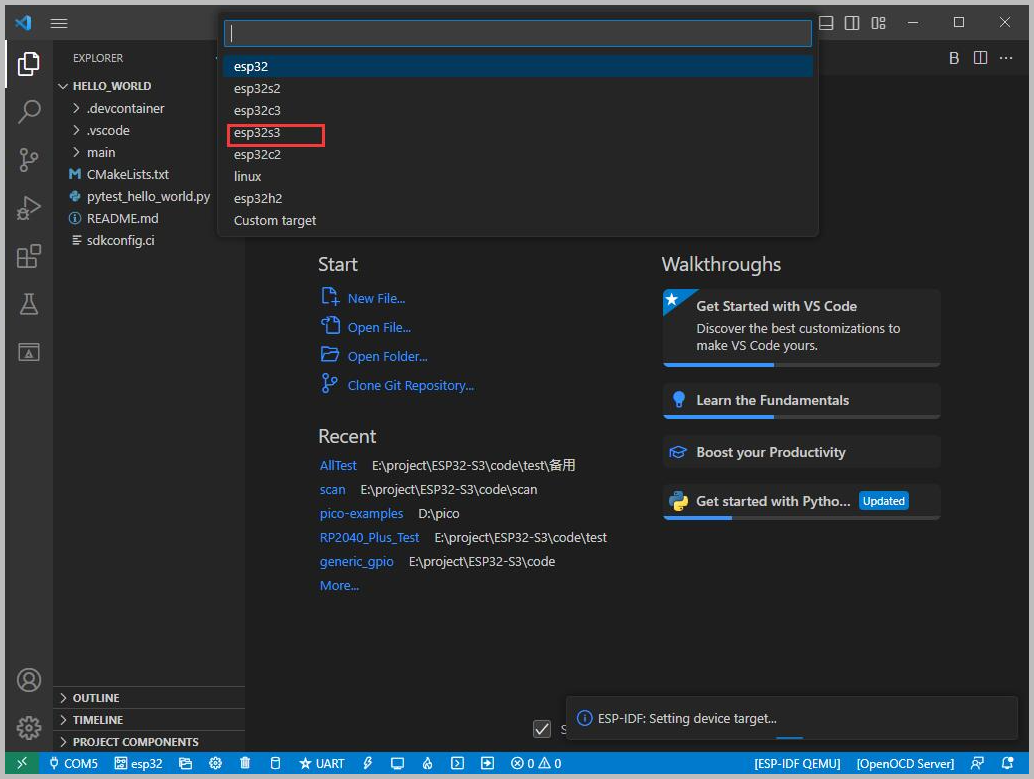
Wait a moment after clicking
-
Select the object we need to drive, i.e., the main chip ESP32-S3
-
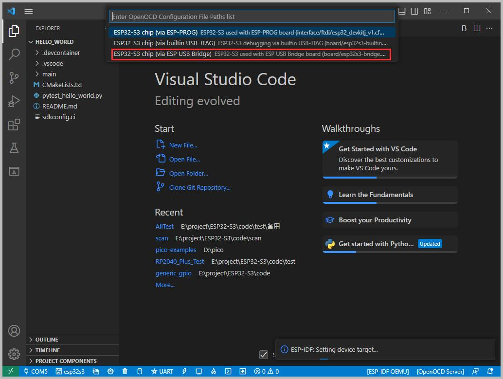
Select the OpenOCD path
NoteThis setting only affects the JTAG/OpenOCD debugging functionality. If you are not using debugging, you can simply choose the default path
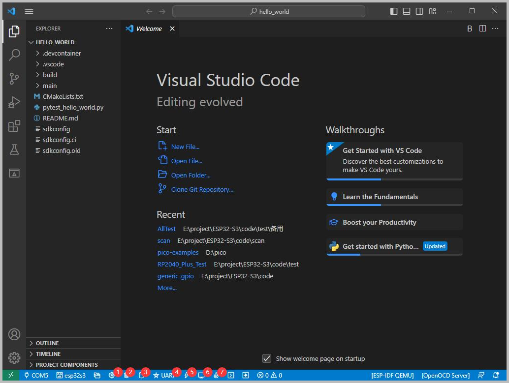
Other Status Bars
-
① SDK Configuration Editor: Many ESP-IDF functions and configurations can be modified here
-
② Full Clean: Clears all compiled files
-
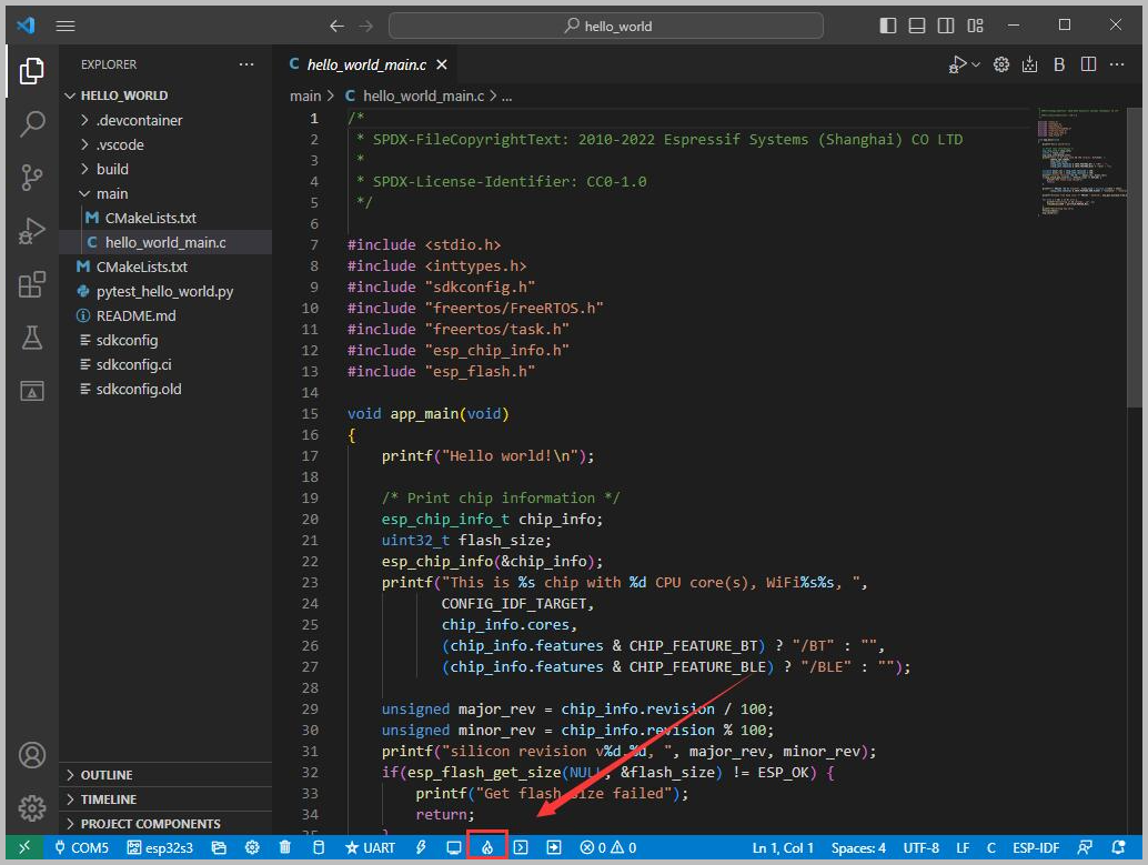
③ Compile
-
④ Current Download Method: Default is UART (onboard USB-to-serial download is the normal case)
-
⑤ Flash the Current Firmware: Please do this after a successful Compilation
-
⑥ Open Serial Monitor: Used to view serial output information. If a port occupancy error occurs, please close the software occupying the port or stop the monitor
-
⑦ One-click Button for Compile + Flash + Open Serial Monitor (most commonly used during debugging)
Compile, Flash and Serial Port Monitoring
-
Click the one-click button for Compile + Flash + Open Serial Monitor introduced above
-
Compilation may take a while, especially the first time.
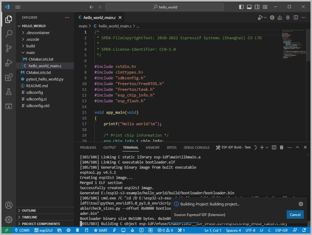
- The first compilation downloads dependencies and generates cache files, which may result in high CPU usage; this is normal
- Subsequent compilations will be significantly faster
-
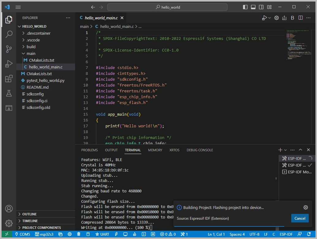
This development board uses the CH343 as the USB-to-serial chip and features an automatic download circuit. It can enter download mode automatically without pressing any buttons
-
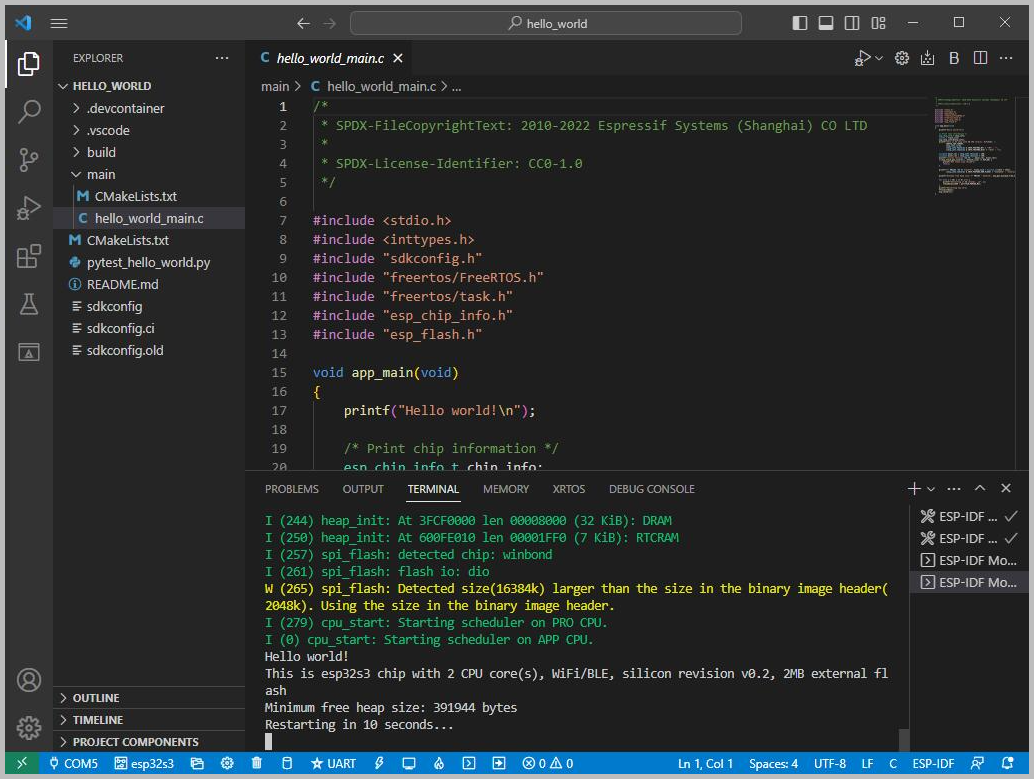
After a successful download, the serial monitor will automatically start. You can see the corresponding information output by the chip, and it will prompt a restart after 10 seconds
Location and Network Communication Demos
Example path: ESP32-S3-A-SIM7670X-4G-V2 → ESP-IDF
GNSS
Hardware Connection
- Connect the GNSS ceramic antenna to the GNSS antenna interface and place it in an open outdoor environment for testing (rainy or cloudy weather may affect satellite acquisition). After powering on the module, it typically takes about 1 minute to receive a valid positioning signal.
Since GNSS satellite acquisition is unstable indoors, it is recommended to test the module or antenna on a balcony, near a window, or in an unobstructed outdoor environment for better positioning results.
Software Operation
-
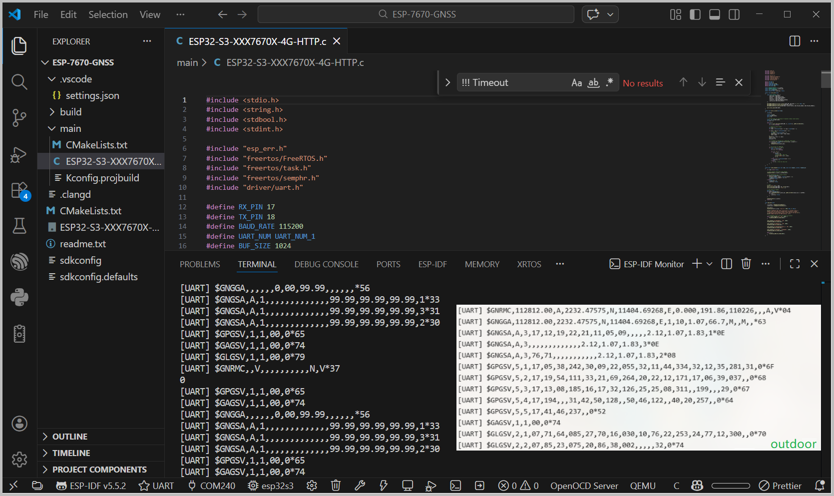
After setting up the development environment according to the tutorial above, modify the corresponding COM port and driver configuration, then click to compile and flash the program. After running, you can receive NMEA sentences output by the GNSS via the serial port. Once positioning is successful, information such as latitude and longitude can be obtained, as shown in the figure below:
TCP
Hardware Connection
- Connect the 4G antenna to the LTE antenna interface and insert a valid SIM card, ensuring good signal coverage. It is recommended to test in an environment with stable signal.
Software Operation
-
After configuring the development environment, modify the server address, port number, and APN parameters in the example as needed. Confirm that the COM port is set correctly, then compile and flash the program. After running, you can view the data sent by the module on the TCP server side, as shown in the figure below:
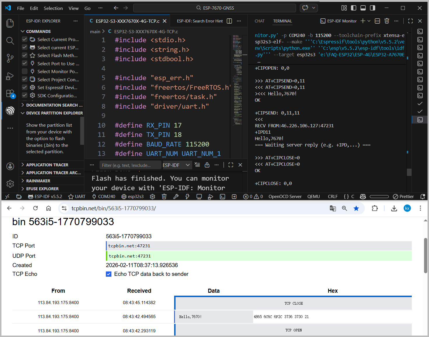
This example uses a publicly accessible TCP test server. This server is intended for functional verification only. For actual projects, it is recommended to set up your own dedicated server.
HTTP
Hardware Connection
- Connect the 4G antenna and insert a functional data SIM card. Ensure the module successfully registers with the network and obtains an IP address.
Software Operation
-
After setting up the development environment, modify the URL address and related parameters in the HTTP example as needed. Confirm that the COM port is set correctly. Compile and flash the program, then open the serial monitor to view the HTTP request process and the response data returned by the server, as shown in the figure below:
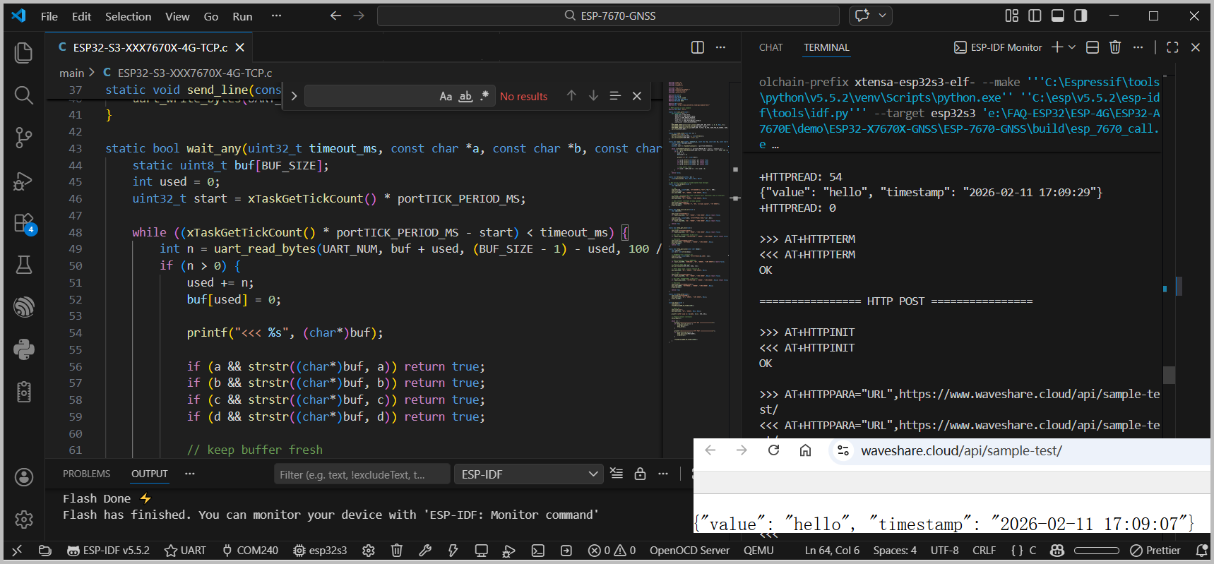
This example uses the Waveshare Cloud Platform's HTTP server. This interface is intended for testing and verification only. For actual projects, you can choose or set up your own server as needed.