ESP32-S3-CAN-2CH
- ESP32-S3-CAN-2CH (Onboard Antenna)
- ESP32-S3-CAN-2CH-U (External Antenna)
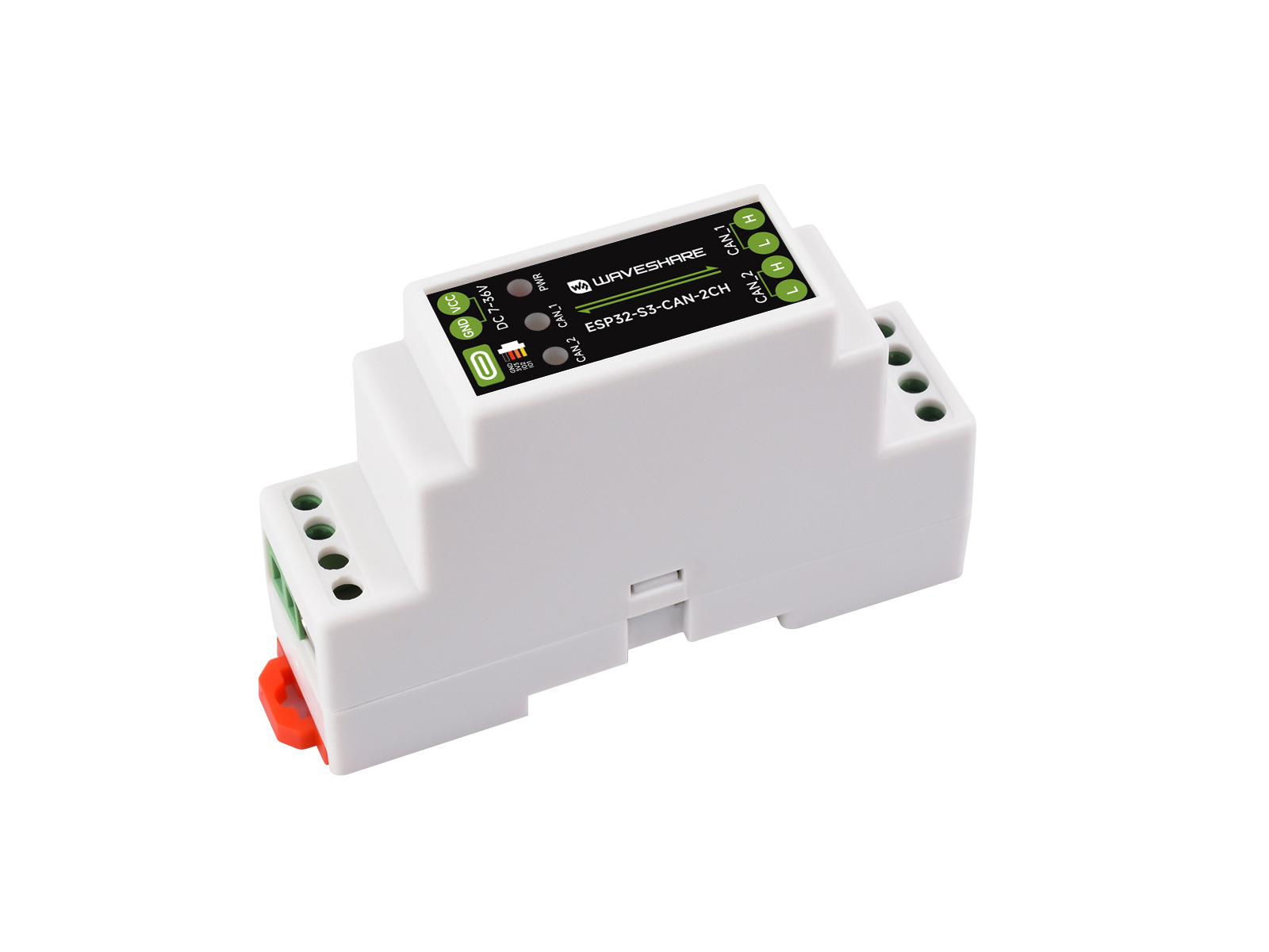
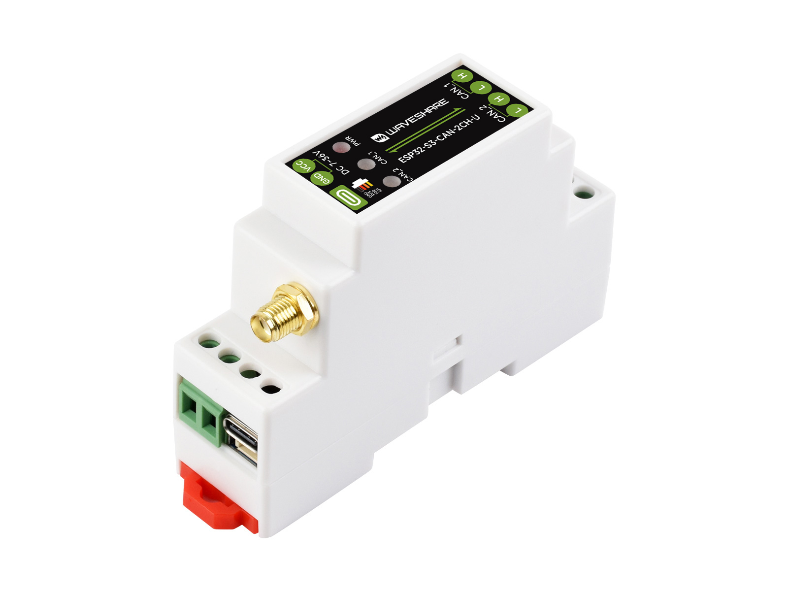
If you are looking for:
- Coding with AI tools: Click Ask AI and select an AI tool to ask questions about this page, or choose Copy page to copy its content and paste it into an AI tool for coding assistance.
- Schematics, datasheets, and example code: See Resources
- Arduino development: See Working with Arduino
- Troubleshooting: See FAQ or contact Technical Support
| SKU | Product |
|---|---|
| 35815 | ESP32-S3-CAN-2CH |
| 35882 | ESP32-S3-CAN-2CH-U |
Product Overview
The ESP32-S3-CAN-2CH is an industrial-grade Wi-Fi wireless communicator based on the ESP32-S3 main controller, supporting peripheral interfaces such as Wi-Fi, Bluetooth, and CAN. It features built-in power isolation, optocoupler isolation, and other protection circuits, making it safe, stable, and reliable for AIoT applications.
Features
- Based on ESP32-S3 microcontroller with Xtensa 32-bit LX7 dual-core processor with frequency up to 240MHz
- Integrated 2.4 GHz Wi-Fi and Bluetooth 5 (LE) dual-mode wireless communication with excellent RF performance
- Two onboard isolated CAN interfaces for easy expansion and connection to various CAN devices
- Onboard pin header, allowing access to other devices
- Onboard USB Type-C port for power supply, firmware downloading and debugging, making development more convenient
- Onboard power supply screw terminal, supports 7-36V wide voltage input, suitable for industrial applications
- Onboard RTC clock chip, supports timing tasks
- Onboard digital isolation to avoid external signal interference with the control chip
- Onboard integrated power isolation, providing stable isolation voltage, no extra power supply required for the isolated terminal
- Onboard CAN working indicator lights for easily monitoring the device's operating status
- Rail-mounted protective enclosure, easy to install, safe to use
Specifications
| Model | ESP32-S3-CAN-2CH | ESP32-S3-CAN-2CH-U | |
|---|---|---|---|
| Antenna Interface | Onboard SMD ceramic antenna | External antenna | |
| Microcontroller | ESP32-S3 (ESP32-S3R8 chip by default, customizable) | ||
| Wireless Communication | 2.4 GHz Wi-Fi (802.11 b/g/n), Bluetooth 5 (LE) | ||
USB | Interface Type | USB Type-C | |
| Supply Voltage | 5V | ||
| Function | Power supply, USB communication, firmware downloading, etc. | ||
Isolated | Interface Type | Screw terminal | |
| Communication Protocol | Supports CAN 2.0A / CAN 2.0B, | ||
| Interface Protection | Provides TVS diode protection, surge protection, and ESD protection | ||
| Matching Resistor | NC by default, with a reserved 120R matching resistor that can be enabled via jumper cap | ||
| Indicator | PWR | Power indicator, steady red when powered by USB or external power | |
| CAN_1 | CAN indicator, blinks when there is data communication on the CAN interface | ||
| CAN_2 | |||
| Power Supply Screw Terminal | Power Supply Range | 7V - 36V | |
| Appearance | Case | DIN-rail protective case | |
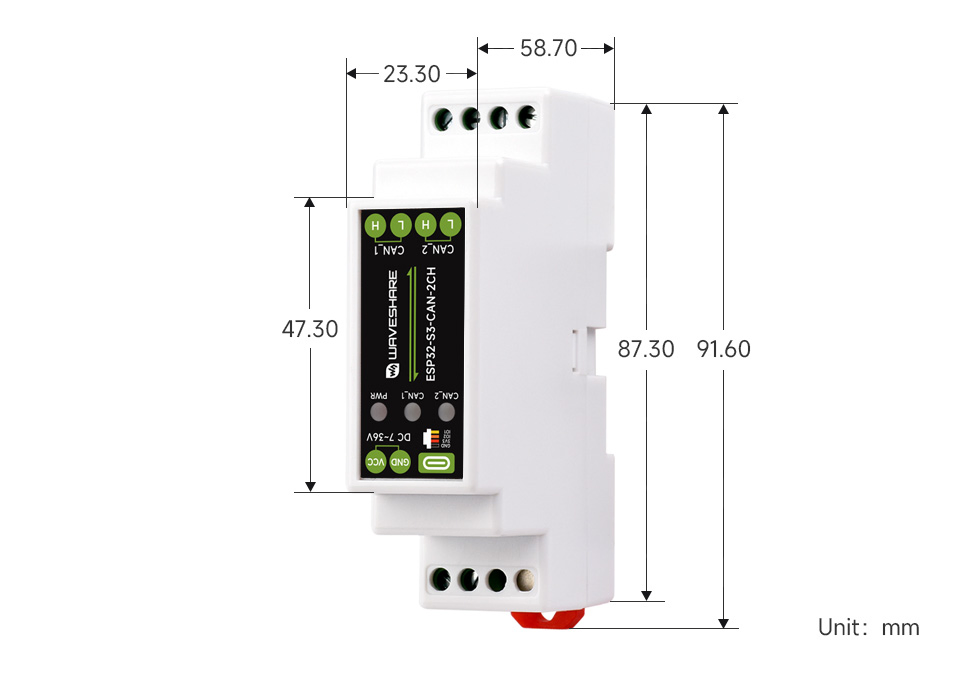
| Dimensions | 91.6 × 23.3 × 58.7 (mm) | ||
Onboard Resources
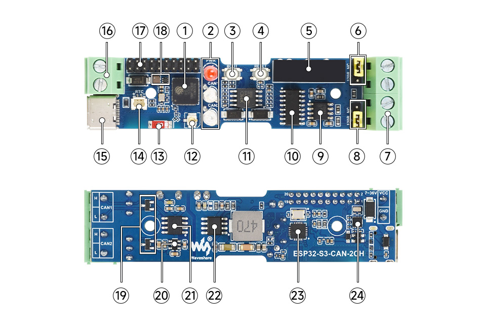
- ESP32-S3 Up to 240 MHz, equipped with 2.4 GHz Wi-Fi and Bluetooth LE
- LED indicators
- PWR: Power indicator
- CAN_1: Lights green when data is sent from the CAN_1 interface, lights blue when data is received from the CAN_1 interface
- CAN_2: Lights green when data is sent from the CAN_2 interface, lights blue when data is received from the CAN_2 interface
- ESP32 BOOT button
- ESP32 RESET button
- Power isolation Provides stable isolation voltage, no additional power supply required on the isolated side
- CAN_1 matching resistor Reserved 120R matching resistor, can be enabled with jumper cap
- CAN communication interface Used to connect external CAN devices
- CAN_2 matching resistor Reserved 120R matching resistor, can be enabled with jumper cap
- CAN transceiver chip
- Digital isolation Prevents external signals from interfering with the control chip
- 16MB Flash
- IPEX 1 connector The external antenna version connects an external antenna through this connector (routed out via the SMA connector on the enclosure)
- Onboard ceramic antenna The onboard antenna version uses this onboard antenna
- RTC battery header For connecting a rechargeable RTC battery (SH1.0)
- USB Type-C port Can be used for device power supply, firmware download, and USB communication
- Power supply screw terminal Supports DC 7-36V wide voltage input
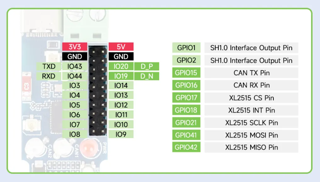
- Pin header (2.0mm pitch) Can connect other functional modules via the pin header
- DC-DC power module Power module, supports up to 3.3 V 2 A output
- TVS diode (Transient Voltage Suppressor) Effectively suppresses surge voltage and transient spike voltage in the circuit
- ME6217C33M5G Low dropout LDO, current (Max) 800 mA
- CAN transceiver chip
- DC-DC power chip
- XL2515QF20 CAN controller
- RTC chip PCF85063 RTC clock
Interface Introduction
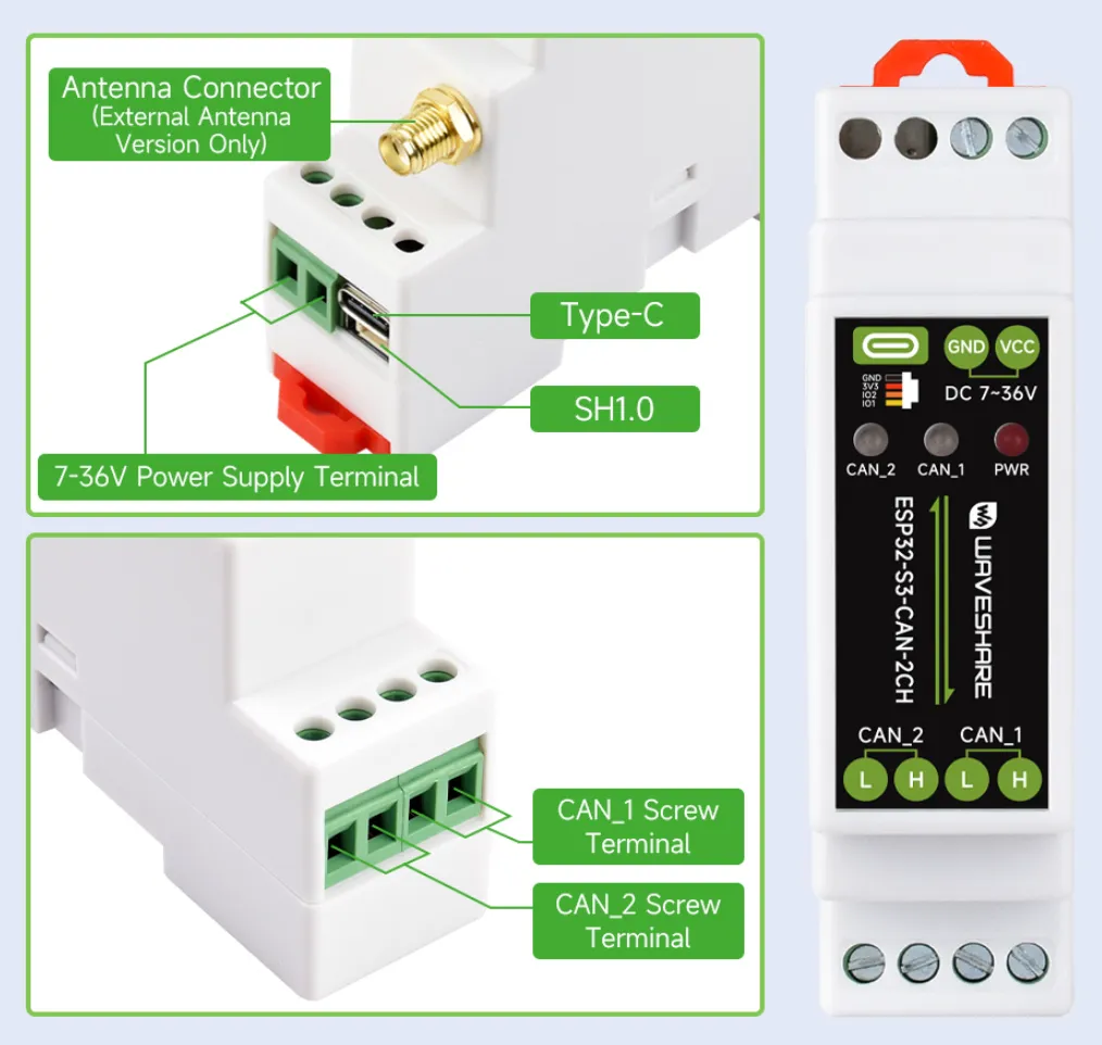
| Upper Terminal Description | Lower Terminal Description | |||
|---|---|---|---|---|
| Power Terminal | Power positive: DC 7V - 36V | CAN_1 Terminal | H signal pin | |
| Power negative | ||||
| Type-C | Can be used for device power supply, | L signal pin | ||
| SH1.0 | GND | Ground | CAN_2 Terminal | H signal pin |
| 3V3 | 3.3V power output | |||
| GPIO2 | Exposed I/O | L signal pin | ||
| GPIO1 | Exposed I/O | |||
Dimensions
Warning: This product is intended only for lawful development, learning, research, and industrial use. It is strictly prohibited to connect to any CAN bus for unauthorized cracking, tampering, unlocking, or function hijacking. Such actions may constitute illegal offenses. The user shall bear all legal liability and consequences of any incidents, and the company assumes no responsibility. We also provide no technical support for such applications.